Instruksi Set Prosesor 8088 Instruction Format q General


, AL RCR Delay JP ulang")
- Slides: 24
Instruksi Set Prosesor 8088
Instruction Format q General Format of Instructions Label: Opcode Operands ; Comment Ø Label: It is optional. It provides a symbolic address that can be used in branch instructio Ø Opcode: It specifies the type of instructions Ø Operands: Instructions of 80 x 86 family can have one, two, or zero operand Ø Comments: Only for programmers’ reference q Machine Code Format Opcode MOV AL, BL Mode Operand 1 Operand 2 100011000011 MOV Register mode
What is the Meaning of Addressing Modes? Ø When a CPU executes an instruction, it needs to know where to get data and where to store results. Such information is specified in the operand fields of the instruction. 100011000011 Opcode MOV AL, BL Mode Operand 1 Operand 2 Ø An operand can be: — A datum — A register location — A memory location Ø Addressing modes define how the CPU finds where to get data and where to store results
Immediate Addressing Ø Data needed by the processor is contained in the instruction For Example: move 7 to register AL AL MOV AL, 7 AH 7 Machine code of MOV AL, 7 101100000111 7 AL Indicate 8 -bit data operation Move an immediate datum to a register
Register Addressing Ø Operands of the instruction are the names of internal register Ø The processor gets data from the register locations specified by instruction operands For Example: move the value of register BL to register AL MOV AL, BL AH AL BH BL q If AX = 1000 H and BX=A 080 H, after the execution of MOV AL, BL what are the new values of AX and BX? In immediate and register addressing modes, the processor does not access memory. Thus, the execution of such instructions are fast.
Direct Addressing Ø The processor accesses a memory location Ø The memory location is determined by the value of segment register DS and the displacement (offset) specified in the instruction operand field DS 10 H + Displacement = Memory location — Example: assume DS = 1000 H, AX = 1234 H MOV [7000 H], AX AH 12 DS: 1 0 0 0 _ + Disp: 7 0 0 0 17000 AL 34 12 17001 H 34 17000 H
Register Indirect Addressing Ø One of the registers BX, BP, SI, DI appears in the instruction operand field. Its value is used as the memory displacement value. For Example: MOV DL, [SI] Ø Memory address is calculated as following: DS 10 H + BX SI DI = Memory address SS BP q If BX, SI, or DI appears in the instruction operand field, segment register DS is used in address calculation q If BP appears in the instruction operand field, segment register SS is used in address calculation
Register Indirect Addressing Ø Example 1: assume DS = 0800 H, SI=2000 H DH MOV DL, [SI] 0 A 000 H DL 12 12 DS: 0 8 0 0 _ + SI: 200 0 memory Ø Example 2: assume SS = 0800 H, BP=2000 H, DL = 7 MOV [BP], DL 0 A 000
Instructions for Stack Operations q What is a Stack ? — A stack is a collection of memory locations. It always follows the rule of last-in-firs-out — Generally, SS and SP are used to trace where is the latest date written into stack q PUSH Source — Push data (word) onto stack — It does not modify flags — For Example: PUSH AX (assume ax=1234 H, SS=1000 H, SP=2000 H before PUSH AX) SS: SP 1000: 1 FFD ? ? 1000: 1 FFE 34 1000: 1 FFF ? ? 1000: 1 FFF 12 1000: 2000 ? ? Before PUSH AX, SP = 2000 H SS: SP After PUSH AX, SP = 1 FFEH 12 34 AX Ø Decrementing the stack pointer during a push is a standard way of implementing stacks in hardware
Instructions for Stack Operations q PUSHF — Push the values of the flag register onto stack — It does not modify flags q POP Destination — Pop word off stack — It does not modify flags — For example: POP AX SP 1000: 1 FFD ? ? 1000: 1 FFE 34 1000: 1 FFF 12 1000: 2000 EC Before POP, SP = 1 FFEH SP After POP AX, SP = 2000 H q POPF — Pop word from the stack to the flag register — It modifies all flags 12 34 AX
Bit Manipulation Instructions q RCL Destination, Count — Left shift destination bits; the number of bits shifted is given by operand Count — The MSB of the destination is shifted into CF; the old CF value goes to the LSB of the destination — Operand Count can be either an immediate data or register CL — Destination can be a register or a memory location MSB LSB — It modifies flags: CF OF PF SF ZF CF Destination q RCR Destination, Count — Right shift destination bits; the number of bits shifted is given by operand Count — The LSB of the destination is shifted into CF, the old CF value goes to the MSB of the destination — Operand Count can be either an immediate data or register CL — Destination can be a register or a memory location — It modifies flags: MSB CF OF PF SF ZF LSB Destination CF
Program Transfer Instructions q JMP Target — — Unconditional jump It moves microprocessor to execute another part of the program Target can be represented by a label, immediate data, registers, or memory location It does not affect flags Ø The execution of JMP instruction JMP 1234 H : 2000 H Current instruction 1234 H 2000 H Next Instruction Address 14340 H JMP CS Jump IP Next instruction
Program Transfer Instructions Ø Conditional Jumps § JZ: Label_1 — If ZF =1, jump to the target address labeled by Label_1; otherwise, do not jump § JNZ: Label_1 — If ZF =0, jump to the target address labeled by Label_1; otherwise, do not jump Ø Other Conditional Jumps JNC JNE JPO JGE JAE JE JP JNL JNB JNS JPE JL JC JS JA JNGE JB JNO JBNE JG JNAE JO JBE JNLE JNG JNP JNA JLE § JCXZ: Label_1 — If CX =0, jump to the target address labeled by Label_1; otherwise, do not jump
Program Transfer Instructions q LOOP Short_Label — It is limited for short jump — Execution Flow: CX = CX – 1 If CX != 0 Then JMP Short_Label End IF q LOOPE/LOOPZ Short_Label CX = CX – 1 If CX != 0 & ZF=1 Then JMP Short_Label End IF q LOOPNE/LOOPNZ Short_Label CX = CX – 1 If CX != 0 & ZF=0 Then JMP Short_Label End IF
Subroutine Instructions Ø A subroutine is a collection of instructions that can be called from one or more other locations within a program q CALL Procedure-Name — Example • • • MOV AL, 1 The order of execution: CALL M 1 MOV BL, 3 MOV AL, 1 • • • MOV CL, 2 M PROC MOV BL, 3 MOV CL, 2 RET M ENDP — Intersegment CALL: the subroutine is located in a different code segment — Intrasegment CALL: the subroutine is located in the same code segment — Use assembler directives far and near to distinguish intersegment and intrasegment CALL
Subroutine Instructions Ø What does the microprocessor do when it encounters a CALL instruction? 1. 2. Push the values of CS and IP (which specify the address of the instruction immediate following the CALL instruction) into stack. If it is a intrasegment CALL, just push the value of IP into stack. Load the new values to CS and IP such that the next instruction that the microproces will fetch is the first instruction of the subroutine — Example: What are in the stack. model small Stack before after the execution 0000. code of CALL? CALL 0000 B 0 02 MOV AL, 2 How about if the 0002 E 8 0002 CALL m 1 CALL is an intersegment 0005 B 3 03 MOV BL, 3 CALL? 0007 B 7 05 0009 C 3 000 A m 1 Proc MOV BH, 5 RET m 1 ENDP end 12345 H 11
Subroutine Instructions q RET — It lets the microprocessor exit from a subroutine — If it is used in a FAR procedure, RET pops two words from the stack. The first one goes to IP register. The second one goes to CS register — If it is used in a NEAR procedure, RET pops one word from stack to IP register — Example: 1234: 2345 1234: 2348 1234: 234 D • • • CALL FAR PTR M 1 • • • M 1 PROC FAR 3456: 0120 MOV AL, 0 • • • RET M 1 ENDP What data are pushed into and popped from the stack during the execution of CALL and RET? 01022
Interrupt Instructions q INT Interrupt-Type — This instruction causes the microprocessor to execute an interrupt service routine. The Interrupt-Type is an immediate data (0 -255) which specifies the type of interrupt — It results in the following operations: 1. 2. 3. 4. Push flag register into stack Clear trace flag and interrupt-enable flag Push CS and IP into stack Load new CS and IP values from the interrupt vector table — Example: • • • 1230: 6789 INT 20 H • • • 62345 H EA After the execution of INT 20 H, what are the data pushed into the stack?
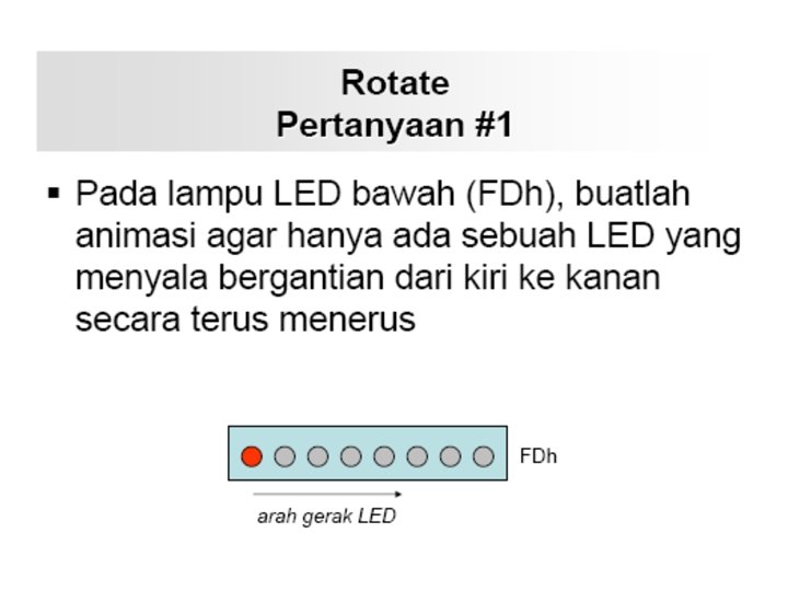
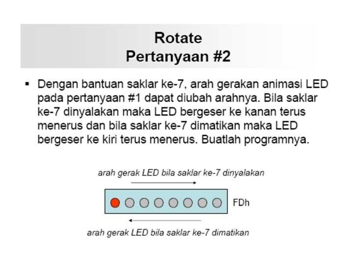
Tugas
Jawab Mov AL, 80 h Ulang: Out (fdh), AL RCR Delay JP ulang