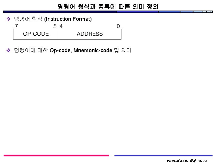
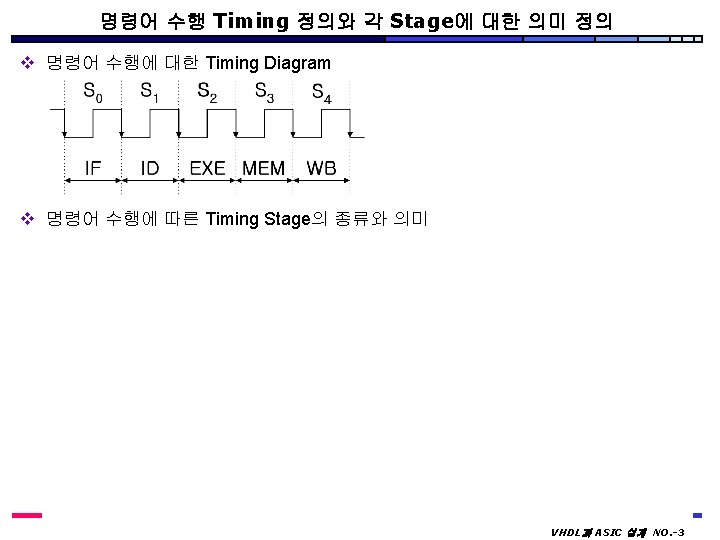
Instruction Fetch VHDL ASIC NO 4 Instruction Decoding


 v 5 -비트 2*1 MUX에 대한 VHDL 표현 v 8")
 v 1증가 회로에 대한 VHDL 표현 library IEEE; use IEEE.")
 v 검증용 Program Data VHDL과 ASIC 설계 NO. -13")
 v ROM에 대한 VHDL 표현 v RAM에 대한 VHDL 표현")
 v Flip-Flop과 Register의 Symbol 정의 v 1 -Bit")
 v 5 -Bit Register에 대한 VHDL 표현 v")

 library IEEE; use IEEE. std_logic_1164. all; package CONTROL_P")
 process(CLK_HOT, OP_D, ZERO_D) variable OP_D_COND : std_logic; begin")
 when S 2 => if OP_D = \"000\"")
 when S 4 => if OP_D_COND = '1'")


- Slides: 27
Instruction Fetch 수행을 위한 하드웨어 정의 VHDL과 ASIC 설계 NO. -4
Instruction Decoding 수행을 위한 하드웨어 정의 VHDL과 ASIC 설계 NO. -5
Instruction Execution 수행을 위한 하드웨어 정의 VHDL과 ASIC 설계 NO. -6
Store into Memory 수행을 위한 하드웨어 정의 VHDL과 ASIC 설계 NO. -8
Write Back into Accumulator 수행을 위한 하드웨어 정의 VHDL과 ASIC 설계 NO. -9
조합논리회로에 대한 VHDL 설계(1) v 5 -비트 2*1 MUX에 대한 VHDL 표현 v 8 -비트 2*1 MUX에 대한 VHDL 표현 library IEEE; use IEEE. std_logic_1164. all; entity MUX 5 is port ( A, B : in std_logic_vector(4 downto 0); SEL : in std_logic; Y : out std_logic_vector(4 downto 0)); end MUX 5; architecture RTL of MUX 5 is begin process(A, B, SEL) begin if SEL=’ 1’ then Y <= A; elsif SEL=’ 0’ then Y <= B; else Y <= “-----“; end if; end process; end RTL; library IEEE; use IEEE. std_logic_1164. all; entity MUX 8 is port ( A, B : in std_logic_vector(7 downto 0); SEL : in std_logic; Y : out std_logic_vector(7 downto 0)); end MUX 8; architecture RTL of MUX 8 is begin process(A, B, SEL) begin if SEL=’ 1’ then Y <= A; elsif SEL=’ 0’ then Y <= B; else Y <= “----“; end if; end process; end RTL; VHDL과 ASIC 설계 NO. -11
조합논리회로에 대한 VHDL 설계(2) v 1증가 회로에 대한 VHDL 표현 library IEEE; use IEEE. std_logic_1164. all; use IEEE. std_logic_unsigned. all; entity INC is port ( PC_ADDR : in std_logic_vector(4 downto 0); INC_ADDR : out std_logic_vector(4 downto 0)); end INC; architecture RTL of INC is begin INC_ADDR <= PC_ADDR + 1; end RTL; v ALU에 대한 VHDL 표현 library IEEE; use IEEE. std_logic_1164. all; use IEEE. std_logic_unsigned. all; entity ALU is port (OPCODE: in std_logic_vector(2 downto 0); OP 1, OP 2 : in std_logic_vector(7 downto 0); ZERO_FLAG : out std_logic; ALU_OUT : out std_logic_vector(7 downto 0)); end ALU; architecture RTL of ALU is begin process(OPCODE, OP 1, OP 2) variable TMP: std_logic_vector(7 downto 0); begin case OPCODE is when “ 010” => TMP : = OP 1 + OP 2; when “ 011” => TMP : = OP 1 and OP 2; when “ 100” => TMP : = OP 1 xor OP 2; when “ 101” => TMP : = OP 2; when others => TMP : = OP 1; end case; if TMP = 0 then ZERO_FLAG <= ‘ 1’; else ZERO_FLAG <= ‘ 0’; end if; ALU_OUT <= TMP; end process; end RTL; VHDL과 ASIC 설계 NO. -12
Memory에 대한 VHDL 설계(1) v 검증용 Program Data VHDL과 ASIC 설계 NO. -13
Memory에 대한 VHDL 설계(2) v ROM에 대한 VHDL 표현 v RAM에 대한 VHDL 표현 library IEEE; use IEEE. std_logic_1164. all; use IEEE. std_logic_unsigned. all; entity ROM is port ( ROM_ADDR : in std_logic_vector(4 downto 0); ROM_DATA : out std_logic_vector(7 downto 0)); end ROM; architecture RTL of ROM is subtype ROMWORD is std_logic_vector(7 downto 0); type ROMTABLE is array(0 to 31) of ROMWORD; constant ROM_TBL : ROMTABLE : = ( “ 11100011”, ” 0000”, 중간 생략. . . ); begin ROM_DATA <= ROM_TBL(conv_integer(ROM_ADDR)); end RTL; library IEEE; use IEEE. std_logic_1164. all; use IEEE. std_logic_unsigned. all; entity RAM is port (RAM_ADDR : in std_logic_vector(4 downto 0); RAM_IN : in std_logic_vector(7 downto 0); RAM_OUT : out std_logic_vector(7 downto 0); MEM_RD, MEM_WR : in std_logic); end RAM; architecture RAM_A of RAM is subtype WORD is std_logic_vector(7 downto 0); type RAM is array(0 to 31) of WORD; signal TMP: RAM : = (…. . , "0000", "00000001", "0000", "10010000", "0000", ” 0000", "0000"); begin process (MEM_RD, RAM_ADDR, RAM_IN) begin if MEM_RD = '1' then RAM_OUT <= TMP(conv_integer(RAM_ADDR)); elsif MEM_WR = '1' then TMP(conv_integer(RAM_ADDR)) <= RAM_IN; end if; end process; end RAM_A; VHDL과 ASIC 설계 NO. -14
순서 논리 회로에 대한 VHDL 설계(1) v Flip-Flop과 Register의 Symbol 정의 v 1 -Bit Flip-Flop에 대한 VHDL 표현 library IEEE; use IEEE. std_logic_1164. all; entity REG 1 is port ( CLK, RST, D, EN : in std_logic; Q : out std_logic); end REG 1; architecture RTL of REG 1 is begin process(CLK, RST) begin if RST = '0' then Q <= '0'; elsif EN = '1' then if CLK = '0' and CLK'event then Q <= D; end if; end process; end RTL; VHDL과 ASIC 설계 NO. -15
순서 논리 회로에 대한 VHDL 설계(2) v 5 -Bit Register에 대한 VHDL 표현 v 8 -Bit Register에 대한 VHDL 표현 library IEEE; use IEEE. std_logic_1164. all; entity REG 5 is port ( CLK, RST, EN : in std_logic; D : in std_logic_vector(4 downto 0); Q : out std_logic_vector(4 downto 0)); end REG 1; architecture RTL of REG 5 is begin process(CLK, RST) begin if RST = '0' then Q <= (others=>’ 0’); elsif EN = '1' then if CLK = '0' and CLK'event then Q <= D; end if; end process; end RTL; library IEEE; use IEEE. std_logic_1164. all; entity REG 8 is port ( CLK, RST, EN : in std_logic; D : in std_logic_vector(7 downto 0); Q : out std_logic_vector(7 downto 0)); end REG 8; architecture RTL of REG 8 is begin process(CLK, RST) begin if RST = '0' then Q <= (others=>’ 0’); elsif EN = '1' then if CLK = '0' and CLK'event then Q <= D; end if; end process; end RTL; VHDL과 ASIC 설계 NO. -16
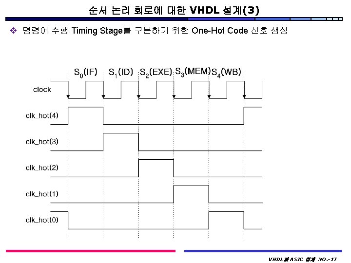
One-Hot Code 생성을 위한 FSM 형태의 VHDL 설계 library IEEE; use IEEE. std_logic_1164. all; entity CLK_GEN is port( CLK, RST : in std_logic; CLK_HOT : out std_logic_vector(4 downto 0)); end CLK_GEN; architecture CLK_GEN_A of CLK_GEN is signal CURRENT_STATE, NEXT_STATE : std_logic_vector(4 downto 0); begin process(CLK, RST) begin if RST = '0' then CURRENT_STATE <= "00000"; elsif CLK = '0' and CLK'event then CURRENT_STATE <= NEXT_STATE; end if; end process; process(CURRENT_STATE) begin if CURRENT_STATE = "00000" then NEXT_STATE <= "00001"; elsif CURRENT_STATE = "00001" then NEXT_STATE <= "00010"; elsif CURRENT_STATE = "00010" then NEXT_STATE <= "00100"; elsif CURRENT_STATE = "00100" then NEXT_STATE <= "01000"; elsif CURRENT_STATE = "01000" then NEXT_STATE <= "10000"; elsif CURRENT_STATE = "10000" then NEXT_STATE <= "00001"; else NEXT_STATE <= "00001"; end if; end process; CLK_HOT <= CURRENT_STATE; end CLK_GEN_A; VHDL과 ASIC 설계 NO. -18
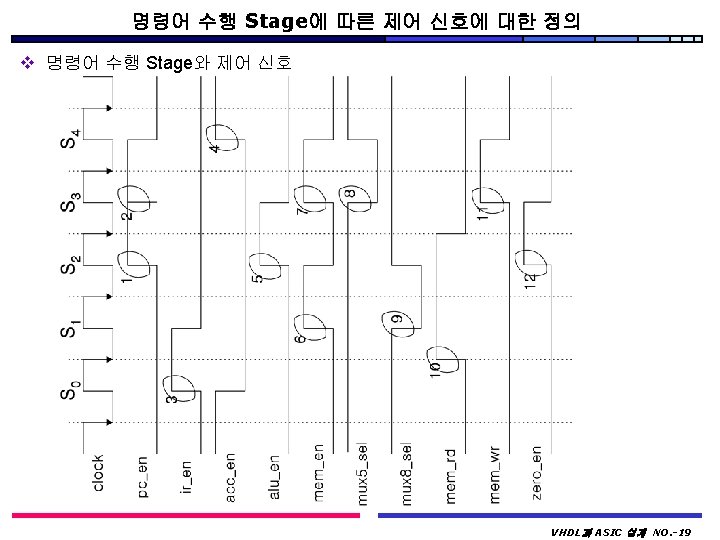
제어 신호 생성에 대한 VHDL 표현(1) library IEEE; use IEEE. std_logic_1164. all; package CONTROL_P is constant S 4 : std_logic_vector(4 downto 0) : = "10000"; constant S 3 : std_logic_vector(4 downto 0) : = "01000"; constant S 2 : std_logic_vector(4 downto 0) : = "00100"; constant S 1 : std_logic_vector(4 downto 0) : = "00010"; constant S 0 : std_logic_vector(4 downto 0) : = "00001"; end CONTROL_P; -library IEEE; use IEEE. std_logic_1164. all; use work. CONTROL_P. all; entity CONTROL is PORT( OP_D : in std_logic_vector(2 downto 0); CLK_HOT : in std_logic_vector(4 downto 0); ZERO_D : in std_logic; CLK_D : in std_logic; ACC_EN_D : out std_logic; ALU_REG_EN_D : out std_logic; MEM_RD_D : out std_logic; MEM_WR_D : out std_logic; PC_EN_D : out std_logic; IR_EN_D : out std_logic; MEM_REG_EN_D : out std_logic; ZERO_EN : out std_logic; MUX 5_SEL : out std_logic; MUX 8_SEL : out std_logic); end CONTROL; architecture CONTROL_A of CONTROL is signal ACC_EN_S, PC_EN_S : std_logic; signal IR_EN_S, ALU_REG_EN_S : std_logic; signal MEM_WR_S, MEM_REG_EN_S : std_logic; signal ZERO_EN_S : std_logic; signal MUX 5_SEL_S, MUX 8_SEL_S : std_logic; begin process(CLK_D) begin if CLK_D = '1' and CLK_D'event then ACC_EN_D <= ACC_EN_S; PC_EN_D <= PC_EN_S; IR_EN_D <= IR_EN_S; ALU_REG_EN_D <= ALU_REG_EN_S; MEM_WR_D <= MEM_WR_S; MEM_REG_EN_D <= MEM_REG_EN_S; ZERO_EN <= ZERO_EN_S; MUX 5_SEL <= MUX 5_SEL_S; MUX 8_SEL <= MUX 8_SEL_S; end if; end process; VHDL과 ASIC 설계 NO. -21
제어 신호 생성에 대한 VHDL 표현(2) process(CLK_HOT, OP_D, ZERO_D) variable OP_D_COND : std_logic; begin if OP_D="010" or OP_D="011" OR OP_D="100" then OP_D_COND : = '1'; else OP_D_COND : = '0'; end if; case CLK_HOT is when S 0 => ACC_EN_S <= '0'; PC_EN_S <= '0'; MEM_WR_S <= '0'; MEM_RD_D <= '0'; IR_EN_S <= '1'; MUX 5_SEL_S <= '1'; MUX 8_SEL_S <= '1'; MEM_REG_EN_S <= '0'; ALU_REG_EN_S <= '0'; ZERO_EN_S <= '0'; when S 1 => ACC_EN_S <= '0'; PC_EN_S <= '0'; MEM_WR_S <= '0'; IR_EN_S <= '0'; MUX 5_SEL_S <= '1'; if OP_D_COND = '1' or OP_D = "101" then MEM_REG_EN_S <= '1'; MEM_RD_D <= '1'; else MEM_REG_EN_S <= '0'; MEM_RD_D <= '0'; end if; if OP_D_COND = '1' or OP_D = "101" then MUX 8_SEL_S <= '0'; else MUX 8_SEL_S <= '1'; end if; ALU_REG_EN_S <= '0'; ZERO_EN_S <= '0'; VHDL과 ASIC 설계 NO. -22
제어 신호 생성에 대한 VHDL 표현(3) when S 2 => if OP_D = "000" then PC_EN_S <= '0'; else PC_EN_S <= '1'; end if; ACC_EN_S <= '0'; MEM_WR_S <= '0'; IR_EN_S <= '0'; MUX 5_SEL_S <= '1'; if OP_D_COND = '1' or OP_D = "101" then MEM_RD_D <= '1'; else MEM_RD_D <= '0'; end if; if OP_D_COND = '1' then ZERO_EN_S <= '1'; else ZERO_EN_S <= '0'; end if; MUX 8_SEL_S <= '1'; MEM_REG_EN_S <= '0'; if (OP_D_COND = '1') or (OP_D = "101") or (OP_D = "110") then ALU_REG_EN_S <= '1'; else ALU_REG_EN_S <= '0'; end if; when S 3 => if (OP_D = "001" and ZERO_D = '1') or OP_D = "111" then PC_EN_S <= '1'; else PC_EN_S <= '0'; end if; ACC_EN_S <= '0'; IR_EN_S <= '0'; if OP_D = "110" then MEM_WR_S <= '1'; else MEM_WR_S <= '0'; end if; if OP_D = "111" then MUX 5_SEL_S <= '0'; else MUX 5_SEL_S <= '1'; end if; MUX 8_SEL_S <= '1'; ALU_REG_EN_S <= '0'; if OP_D_COND = '1' or OP_D = "101" then MEM_REG_EN_S <= '1'; else MEM_REG_EN_S <= '0'; end if; ZERO_EN_S <= '0'; MEM_RD_D <= '0'; VHDL과 ASIC 설계 NO. -23
제어 신호 생성에 대한 VHDL 표현(4) when S 4 => if OP_D_COND = '1' or OP_D = "101" then ACC_EN_S <= '1'; else ACC_EN_S <= '0'; end if; MEM_WR_S <= '0'; IR_EN_S <= '0'; MUX 5_SEL_S <= '1'; MUX 8_SEL_S <= '1'; ALU_REG_EN_S <= '0'; MEM_RD_D <= '0'; MEM_REG_EN_S <= '0'; PC_EN_S <= '0'; ZERO_EN_S <= '0'; when others => ACC_EN_S <= '0'; PC_EN_S <= '0'; MEM_WR_S <= '0'; MEM_RD_D <= '0'; IR_EN_S <= '1'; MUX 5_SEL_S <= '1'; MUX 8_SEL_S <= '1'; MEM_REG_EN_S <= '0'; ALU_REG_EN_S <= '0'; ZERO_EN_S <= '0'; end case; end process; end CONTROL_A; VHDL과 ASIC 설계 NO. -24
마이크로프로세서에 대한 최상위 레벨에 대한 VHDL 표현 v Entity에 대한 VHDL 표현 entity U_P is port ( RESET, CLOCK : in std_logic); end U_P; v Architecture에 대한 VHDL 표현 architecture U_P_A of U_P is --component에 대한 선언. . . . --중간 기억 장소인 signal에 대한 선언. . . … --사용 Component의 Configuration 정의 begin U 0: MUX 5 port map (PC_ADDR, IR_ADDR, MUX 5_SEL, MUX 5_OUT); U 1: MUX 8 port map (ALU_OUT, RAM_OUT, MUX 8_SEL, MEM_REG_IN); U 2: INC port map (PC_REG_OUT, PC_ADDR); U 3: REG 1 port map (CLOCK, RESET, ZERO_IN, ZERO_EN, ZERO_OUT); U 4: REG 5 port map (CLOCK, RESET, PC_EN, MUX 5_OUT, PC_REG_OUT); U 5: REG 8 port map (CLOCK, RESET, IR_EN, ROM_OUT, IR_OUT); U 6: REG 8 port map CLOCK, RESET, ACC_EN , ACC_IN, ACC_OUT); U 7: REG 8 port map (CLOCK, RESET, ALU_REG_EN, ALU_IN, ALU_OUT); U 8: REG 8 port map (CLOCK, RESET, MEM_REG_EN, MEM_REG_IN, ACC_IN); U 9: ALU port map (OPCODE, ACC_OUT, ACC_IN, ZERO_IN, ALU_IN); U 10: CONTROL port map (OPCODE, CLK_HOT, ZERO_OUT, CLOCK, ACC_EN, ALU_REG_IN, MEM_RD, MEM_WR, PC_EN, IR_EN, EM_REG_IN ZERO_EN, MUX 5_SEL, MUX 8_SEL); U 11: CLK_GEN port map (CLOCK, RESET, CLK_HOT); U 12: ROM port map (PC_REG_OUT, ROM_OUT); U 13: RAM port map (IR_ADDR, ALU_OUT, RAM_OUT, MEM_RD, MEM_WR); end U_P_A; VHDL과 ASIC 설계 NO. -25
검증 기준 값 정의와 Test Bench VHDL 표현 v Program 수행에 대한 검증 기준 값 v Test Bench에 대한 VHDL 표현 library IEEE; use IEEE. std_logic_1164. all; entity TEST_BENCH is end TEST_BENCH; architecture TEST_BENCH_A of TEST_BENCH is component U_P port (RESET, CLOCK : in std_logic); end component; signal RESET : std_logic : ='0'; signal CLOCK : std_logic : ='1'; for U 0: U_P use entity work. U_P(U_P_A); begin U 0 : U_P port map (RESET, CLOCK); RESET <= '1' after 10 ns; CLOCK <= not CLOCK after 5 ns; end TEST_BENCH_A; configuration TEST_BENCH_C of TEST_BENCH is for TEST_BENCH_A end for; end TEST_BENCH_C; VHDL과 ASIC 설계 NO. -26