
Instruction cycle Instruction A command given to the

- Slides: 35
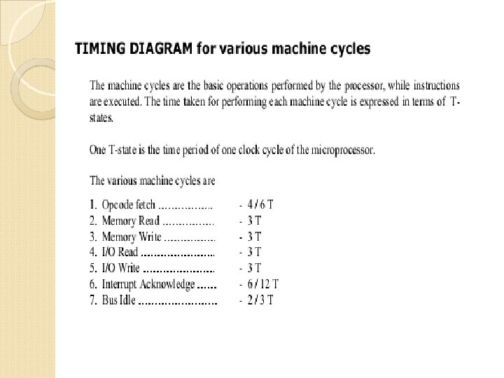
Instruction cycle �Instruction: A command given to the microprocessor to perform an operation �Program : A set of instructions given in a sequential manner to perform a particular task The CPU fetches one instruction from memory at a time & executes it. Instruction cycle = Fetch cycle + Execute cycle
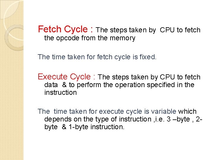
Fetch Cycle : The steps taken by CPU to fetch the opcode from the memory The time taken for fetch cycle is fixed. Execute Cycle : The steps taken by CPU to fetch data & to perform the operation specified in the instruction The time taken for execute cycle is variable which depends on the type of instruction , i. e. 3 –byte , 2 byte & 1 -byte instruction.
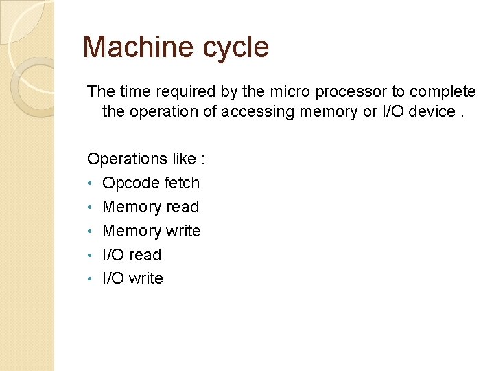
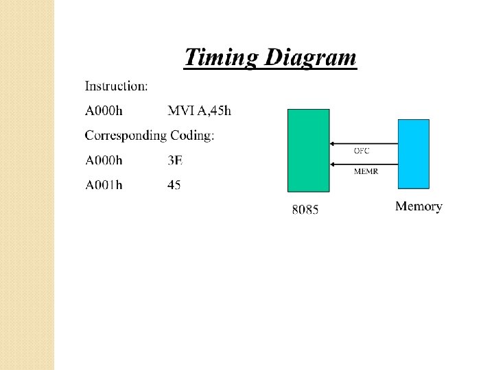
Machine cycle The time required by the micro processor to complete the operation of accessing memory or I/O device. Operations like : • Opcode fetch • Memory read • Memory write • I/O read • I/O write
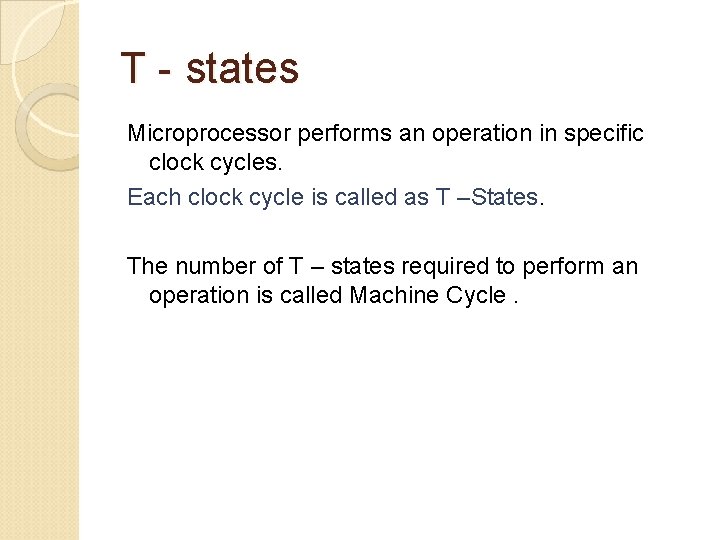
T - states Microprocessor performs an operation in specific clock cycles. Each clock cycle is called as T –States. The number of T – states required to perform an operation is called Machine Cycle.
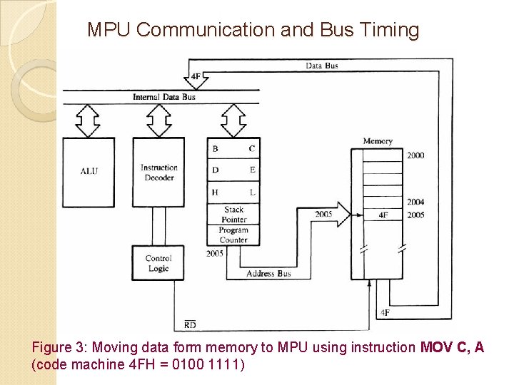
MPU Communication and Bus Timing Figure 3: Moving data form memory to MPU using instruction MOV C, A (code machine 4 FH = 0100 1111)
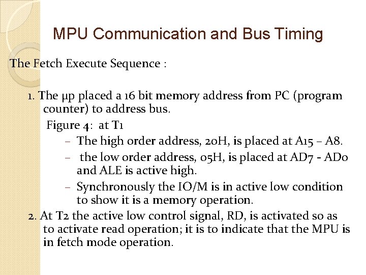
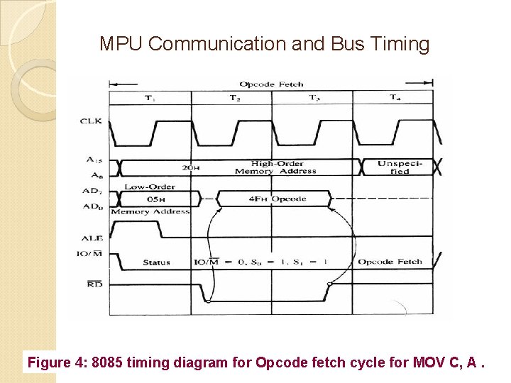
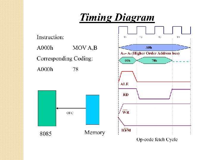
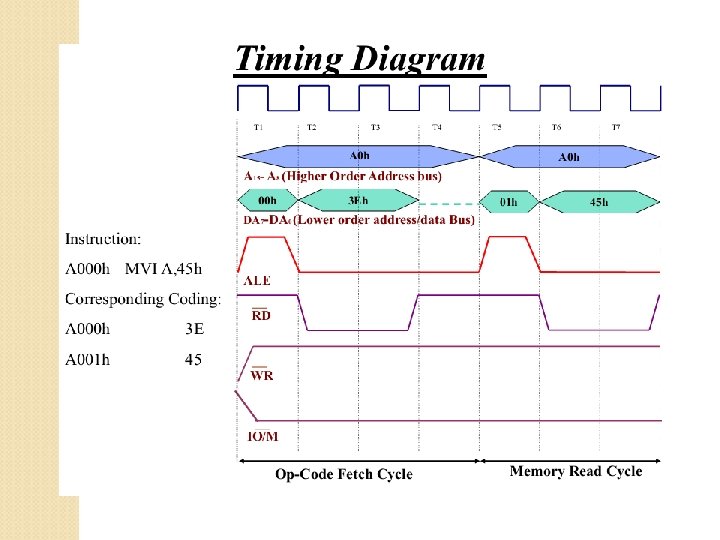
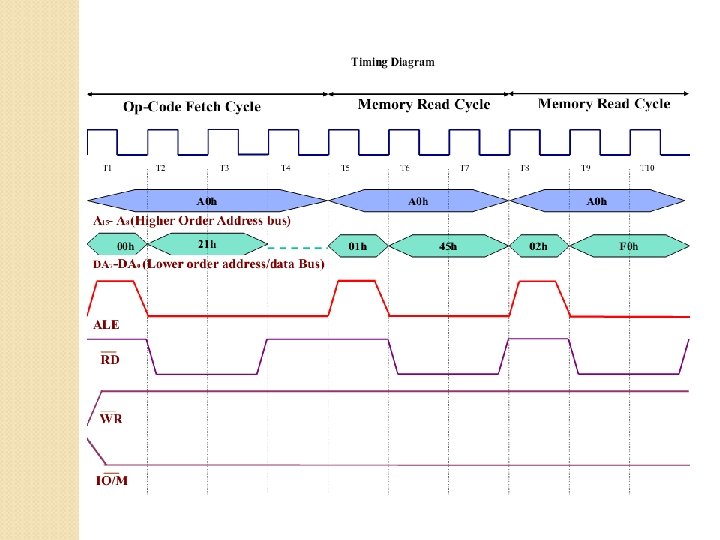
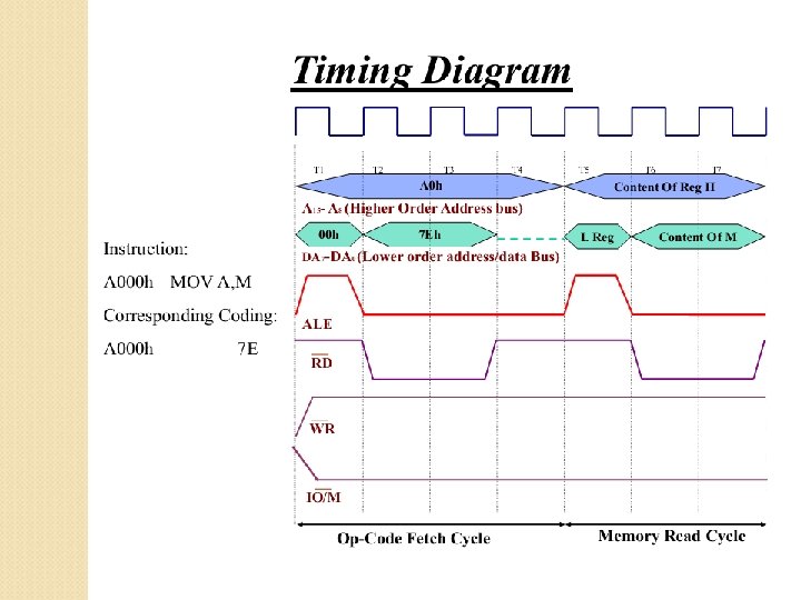
MPU Communication and Bus Timing The Fetch Execute Sequence : 1. The μp placed a 16 bit memory address from PC (program counter) to address bus. Figure 4: at T 1 – The high order address, 20 H, is placed at A 15 – A 8. – the low order address, 05 H, is placed at AD 7 - AD 0 and ALE is active high. – Synchronously the IO/M is in active low condition to show it is a memory operation. 2. At T 2 the active low control signal, RD, is activated so as to activate read operation; it is to indicate that the MPU is in fetch mode operation.
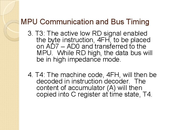
MPU Communication and Bus Timing 3. T 3: The active low RD signal enabled the byte instruction, 4 FH, to be placed on AD 7 – AD 0 and transferred to the MPU. While RD high, the data bus will be in high impedance mode. 4. T 4: The machine code, 4 FH, will then be decoded in instruction decoder. The content of accumulator (A) will then copied into C register at time state, T 4.
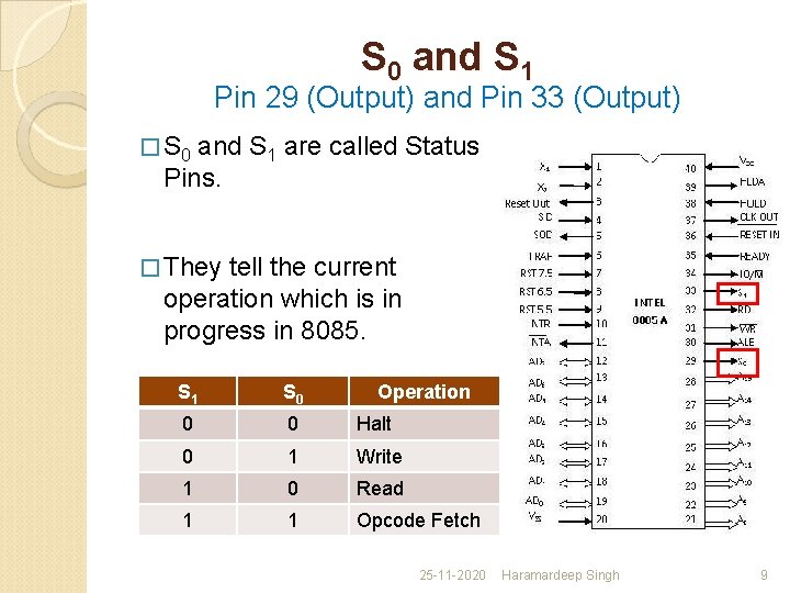
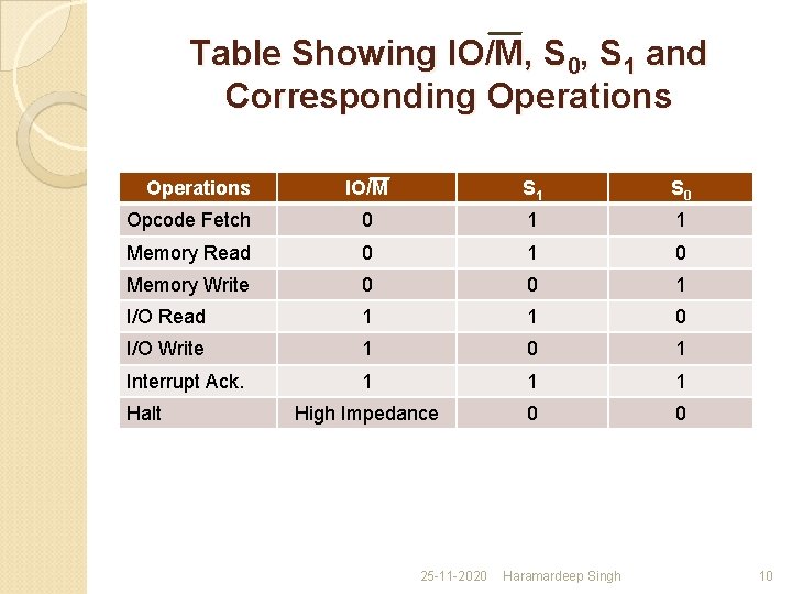
S 0 and S 1 Pin 29 (Output) and Pin 33 (Output) � S 0 and S 1 are called Status Pins. � They tell the current operation which is in progress in 8085. S 1 S 0 Operation 0 0 Halt 0 1 Write 1 0 Read 1 1 Opcode Fetch 25 -11 -2020 Haramardeep Singh 9
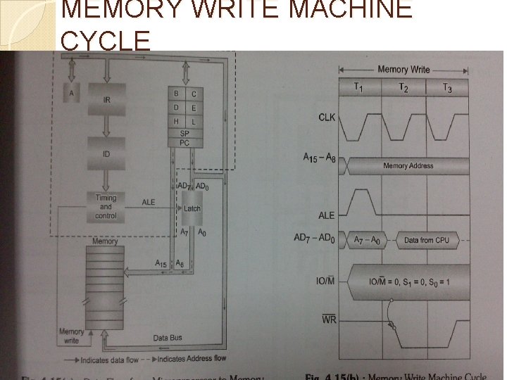
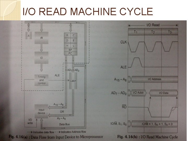
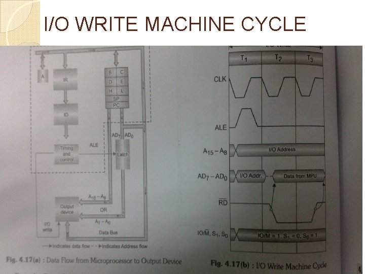
Table Showing IO/M, S 0, S 1 and Corresponding Operations IO/M S 1 S 0 Opcode Fetch 0 1 1 Memory Read 0 1 0 Memory Write 0 0 1 I/O Read 1 1 0 I/O Write 1 0 1 Interrupt Ack. 1 1 1 High Impedance 0 0 Halt 25 -11 -2020 Haramardeep Singh 10
MPU Communication and Bus Timing Figure 4: 8085 timing diagram for Opcode fetch cycle for MOV C, A.
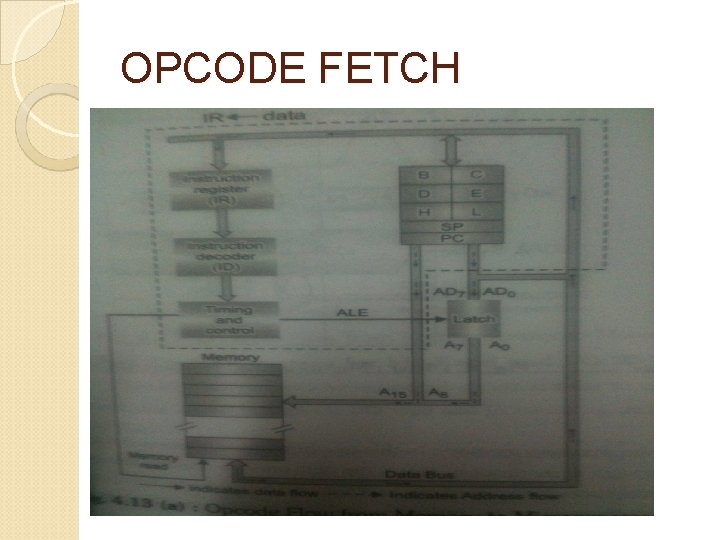
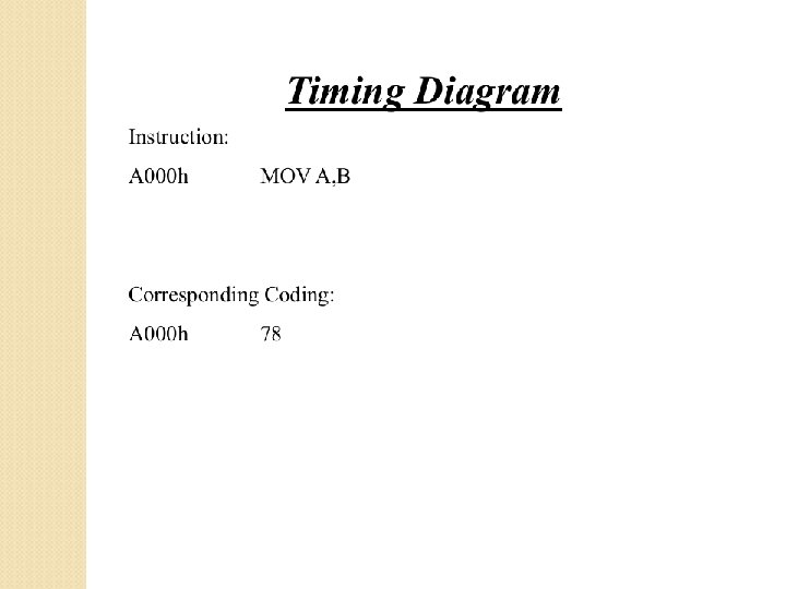
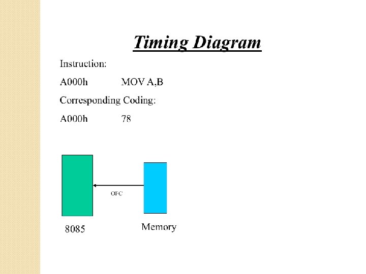
OPCODE FETCH
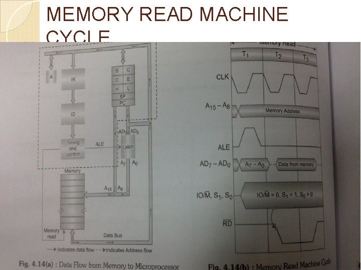
MEMORY READ MACHINE CYCLE
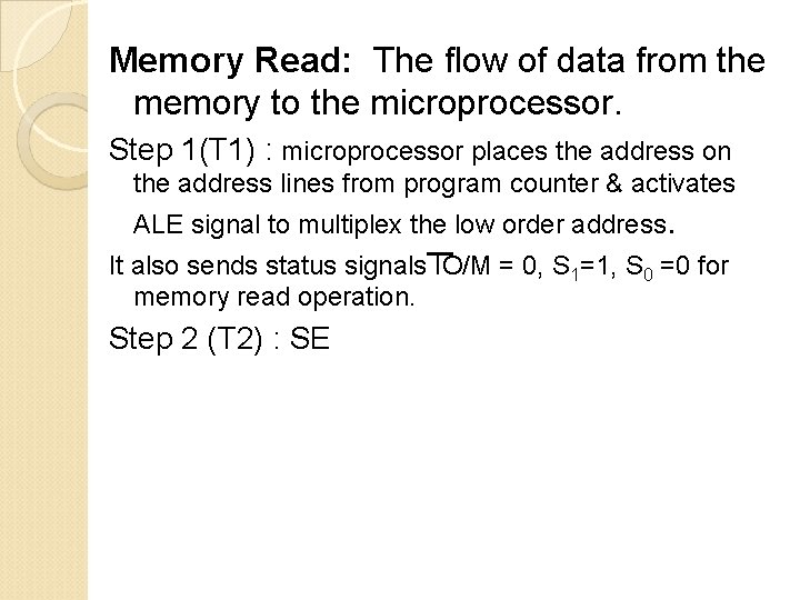
Memory Read: The flow of data from the memory to the microprocessor. Step 1(T 1) : microprocessor places the address on the address lines from program counter & activates ALE signal to multiplex the low order address. It also sends status signals IO/M = 0, S 1=1, S 0 =0 for memory read operation. Step 2 (T 2) : SE
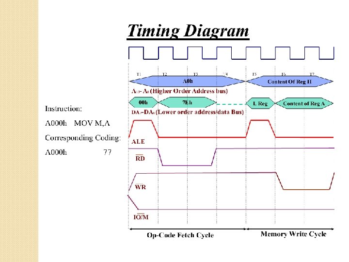
MEMORY WRITE MACHINE CYCLE
I/O READ MACHINE CYCLE
I/O WRITE MACHINE CYCLE
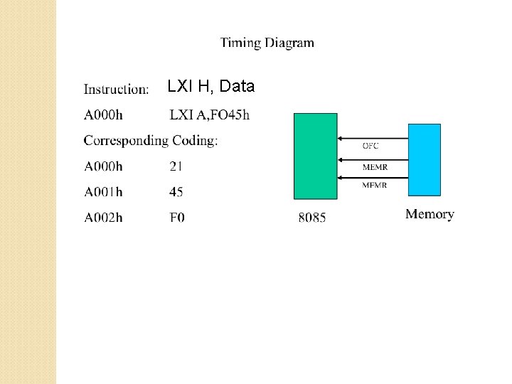
LXI H, Data