Installation And Estimation of Service Connection Content q

 2. Transmission line 1.")


- Slides: 27
Installation And Estimation of Service Connection
Content q. Definition of service connection Service line (distribution line) 2. Transmission line 1. 2. connection Rule no. 77 Rule no. 79 q. Estimate for overhead service q. Meter board connection for q. Selection of service single phase cable q. Estimate for q. Types of service underground service connection for three 1. Overhead service phase connection 2. Underground service connection q. IE rules for service
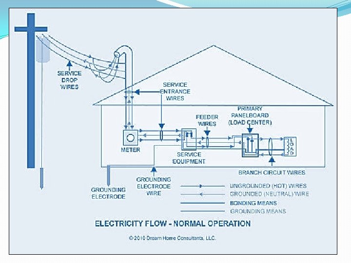
Service Line and Transmission Lines �Transmission line: - The power from the generating station is transmitted to substation by means of the transmission line. �Service line: - The overhead line or cable connection taken from the nearest pole of the service line to the consumer’s premises or their building is called service line or consumers' service connection � GENERATING STATION SUB STATION CONSUMER • • TRANSMISSION LINE SERVICE LINE
�The service connection meet at the point where the supply conductors enter the energymeter. �It is the responsibility of the electricity department to install, maintain and for these we have to pay to the electric supply by conductors and energize the energymeter. �The service line is terminated at
Meter Board
�The service line is protected with kit-kat fuse before it direct enters into the meter for protection of meter against extra high voltage. �But by observing this there were many cases of theft of electricity by having a connection direct from the fuse. �By doing this proper billing can’t be done or there were the stealing of energy. The cut-out is provided on the phase wire and neutral link on neutral wire. � The board on which the cut-out, neutral link and meter are fitted is called meter board or service board. The meter is sealed by the electricity department.
Selection of service cable �The service connection are either given by bare conductor from nearest pole up to consumers premises or by weatherproof cable of aluminum or copper. � In case of bare conductors, the pin type or shackle type insulators are installed on the mild steel bracket fitted on the wall of consumer’s premises from where weatherproof cable is provided for connection to energymeter. �The size of the conductor depend upon the load of the consumer and distance up to service pole for voltage drop calculations.
Types of service connections �T h e s e r v i c e c o n n e c t i o n s a r e o f f o l l o w i n g types A. Overhead service connection: I. Service main for a high roof or double story building II. For single story house or low roof building B. Underground service connection
1. Overhead service connection Diagram for service main for low roof building also
� For the overhead service line, when the service line is provided with the help of an overhead line, it must have fixed clearance above the ground of the lowest conductor and a definite clearance must be provided from the adjacent building. �Overhead service connection can be done for different types of buildings. So here is an overview on different height roof buildings and their diagrams ; 1. Service main for a low roof building 2. Service main for a high roof building Diagram for service main for high roof building also
2. Underground service connection
Use of underground cable is usually made for service connection when the power is to be supplied to the consumer is more than 25 KW.
connection 1. Rule no. 77 q The height of service line conductors erected across a street must not be less than: • For low and medium voltage line =5. 975 m • For high voltage lines=6. 10 m q The height of service line conductors erected along a street must not be less than: • For low and medium voltage line=5. 490 m • For high voltage line=5. 795 m q For extra high voltage line, the clearance ground shall not be less than 5. 185 m plus 0. 305 m for every 33 KV or part
2. Rule no 79 q. Where a low or medium voltage overhead line passes above or adjacent to the building; the following minimum clearances must be as follow: �When the line passes above the building, a vertical distance of 2. 44 m from the highest point of the building �When the line passes adjacent to the building, a horizontal clearance of 1. 22 m from the nearest point.
Estimate For Service Connection For Overhead Line Q. A newly constructed single storeyed house is to be provided with single phase 230 volts, 50 Hz having a load of 5 KW. The supply is to be given from overhead line 20 m away from the building. Prepare a list of material for giving the service connection and also estimate the cost of the service connection. Ans; - Assume: 1. Height of the ground floor=3. 5 m 2. Service connection received at A height of 6 M from the floor.
Diagram for overhead service connection and for the overhead estimate also
Selection of rating of weatherproof, twin core, aluminum conductor cable and line conductor: - total connected load = 5 KW supply voltage =230 volts total load in ampere = 5000 =21. 7 A 230 diversity factor= 60% total connected load= 13. 7 A To met the present load requirement and provision for future requirement even in the event of expansion of the building and any other electrical points in the existing building. It is therefor better that a weatherproof cable of higher rating i. e. about 50% may be used.
�It is therefor suggested that a weatherproof cable of size 1/3. 55 mm or 10 mm 2 , twin core, PVC insulated rated to carry a load of 34 A should be used �The size of installation between supplier’s pole or distribution pole upto insulators on building should also be based on the basis of connected load in the building. It is therefore suggested that a G. I wire of 8 SWG may be used for bare conductors.
List of materials Sr no Specifications Qty. Rate Amount 1 8 SWG G. I wire to serve as a bare conductor from supply pole upto house service connection including wastage 63 m 50/- m 3150/- 2 Weatherproof cable of size 1/3. 35 or 10 mm 2 twin core PVC insulated rated to carry a load of 34 A 7 m 60/-m 420/- 3 G. I pipe of 50 mm dia 7. 5 m 50/-m 375/- 4 Earth wire 8 SWG G. I running along G. I pipe upto meter 6 m board 80/-m 480/- 5 Pipe bend 50 mm dia pipe 3 No 40/- 120/- 6 Pipe clamp to fix earth wire and for stay wire 2 No 100/- 200/- 7 G. I pipe saddles for 50 mm dia pipe 4 No 70/- 280/- 8 L. T shackle insulators with U clamp nut and bolt and other fittings 4 No 500/- 2000/- 9 Iron clad meter board along with 4 No bolts and nut of size 25 cm*30 cm 1 No 1000/- 10 Conduit bushings 50 mm dia for G. I pipe 2 No 150/- 300/- 11 Stay wire 7/10 SWG G. I 7 m 50/-m 350/- 12 Stay bow 1 no 500/-
Specifications Qty. Rate Amount 13 Star rod with bolts and stay buckle and stay plate of size 30 cm*30 cm 1 set 300/- 14 Stay insulator 1 no 500/- 15 Lock nut for 50 mm dia GI pipe (at service board) 1 no 30/- 16 Pole clamp 60 cm long, 50 mm*6 mm holding service bracket with pole 1 no 250/- 17 Aluminum clips 75 mm long to hold earth wire pipe 1 box 300/- 18 Cement 1 bag 500/- 19 Sand 6 bag 150/- 900/- 20 Concrete 4 bag 200/- 800/- 21 Earthing thimbles to hold earth wire with meter board 1 no 200/- 22 2 way junction box 1 no 100/- Total Labor charge Contingency Grand total 13000/2000/1500/17000/-
Estimate for service connection for underground connection Q. A newly constructed ‘Audio Visual Cell’ of a polytechnic is required to be provided with service connection from an existing nearby distribution pole 20 m away. It is required to be provided with an underground service connection. Estimate the quantity of material required for giving underground service connection. The building has following loads: a) Light Load (Light/Fan/5 A socket)= 120 A b) Power Load (15 A socket points) = 80 A Make a complete diagram of the above scheme. Ans: - Assume : a) Height of main board from floor : 1. 5 m b) Service connection received above the ground: 5 m
Diagram for underground service connection and for the underground estimate also
�Selection and rating of weatherproof cable from pole to meter board : �total load connected to the building is 200 A �Diversity factor = 60% �Max load being used = 132 A It is therefore suggested that a weatherproof cable of size 70 mm 2 or 19/2. 24 mm 4 core, PVC insulated aluminum conductor rated to carry a load of 195 A should be used from pole to energymeter. It is also suggested that a G. I pipe of 35 mm diameter should be used alongwith the
The service connection is made to enter the building through a 50 mm conduit laid below the floor upto underground concrete enclosure. The concrete pit is covered by a cast iron. This provides a
Sr no Specification 1 List of material Qty Rate Amount 19/2. 24 mm or 70 mm 2 PVC insulated 4 core 660 volts grade, weatherproof cable 30 m 150/- 4500/- 2 10 SWG G. I wire from pole earth wire to energymeter board 30 m 100/- 3000/- 3 Pole clamp of mild steel with nuts and bolts to hold 1 no earth wire with pole 200/- 4 G. I pipe 35 mm dia to carry cable for main board along wall upto floor 6 m 50/-m 300/- 5 G. I pipe 50 mm dia from outer wall upto underground concrete cable enclosure running below floor 4 m 100/-m 400/- 6 G. I pipe 35 mm dia from concrete cable enclosure upto space for main board through wall vertically 2 m 50/-m 100/- 7 Conduit saddles of Galvanized steel to hold G. I pipe with wall 10 No 20/- 200/- 8 Hooked ray bolt 200 mm long and 15 mm diameter to hold earth wire with wall 4 no 25/- 100/- 9 Iron clad board for installation of main board of size 100 cm*75 cm 1 no 1500/-
Sr no Specifications Qty Rate Amount 10 G. I pipe bend for 35 mm dia G. I pipe 4 No 50/- 200/- 11 Rag bolts with nuts 10 mm dia and 100 mm long to fix conduit saddles with wall 20 No 25/- 500/- 12 Link clips of aluminum 75 mm long to hold cable with support wire OR binding wire of 12 SWG 3 m 100/- 300/- 13 Earthing thimbles 45 A rating with nuts and bolts to connect earth wire with energymeter main switch 2 no. 250 500/- Total Labor charge Contingency 12000/1500/- Grand total 15000/-