INSTABILITIES IN LINACS Massimo FerrarioLNF INFN IT Slangerup

INSTABILITIES IN LINACS Massimo. Ferrario@LNF. INFN. IT Slangerup – June 12 - 2019

OUTLINE • • Introduction and Heuristic model Basic Concepts Beam Break Up in Linear Accelerators BNS damping
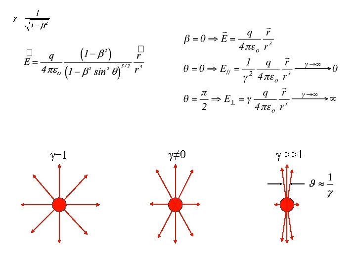

Bunched beam - Circular Perfectly Conducting Pipe - Beam at Centre- Static Approximation a b

Circular Perfectly Conducting Pipe with Transition d b L There is a longitudinal Ez(r, z) field in the transition and a test particle experience a voltage given by: decelerating if d > b Power lost by the beam

For d > b the power is deposited to the energy of the fields: moving from left to right the beam induces the fields in the additional space available d b The additional power passing through the right part of the beam pipe is obtained by integrating the Poynting vector throught the sourface Notice that if d<b the beam gains energy. If d-->∞ the power goes to infinity, such an unphysical result is nevertheless consistent with the original assumption of an infinite energy beam ( ->∞).

Reflected and Diffracted fiels CST MICROWAVE STUDIO®

T 3 P – CLIC Two-Beam Accelerator Compact Linear Collider two-beam accelerator unit PETS Dielectric absorbers (Si. C) TD 24 PETS +TD 24 9

Short Range Wake Fields Effects head tail effects Long Range Wake Fields Effects multibunch instabilities

Energy exchange if:
![f [MHz] (R/Q)* [Ω/cmn] Qext M: TM 010 -9 1300. 00 1161 8∙ 105](http://slidetodoc.com/presentation_image/b0a9484378a95e3b0d4f10cd8e5ae3e6/image-13.jpg "f [MHz] (R/Q)* [Ω/cmn] Qext M: TM 010 -9 1300. 00 1161 8∙ 105")
f [MHz] (R/Q)* [Ω/cmn] Qext M: TM 010 -9 1300. 00 1161 8∙ 105 D: TE 111 -7 a 1717. 15 5. 0 4∙ 104 D: TE 111 -7 b 1717. 21 5. 0 5∙ 104 D: TE 111 -8 a 1738. 12 3. 0 6∙ 104 D: TE 111 -8 b 1738. 15 3. 0 8∙ 104 D: TM 110 -2 a 1882. 15 3. 4 6∙ 103 D: TM 110 -2 b 1882. 47 3. 4 6∙ 103 D: TM 110 -4 a 1912. 04 4. 6 9∙ 103 D: TM 110 -4 b 1912. 21 4. 6 1∙ 104 D: TM 110 -5 a 1927. 10 15. 6 1. 5∙ 104 D: TM 110 -5 b 1927. 16 15. 6 1. 5∙ 104 D: TM 110 -6 a 1940. 25 12. 1 2∙ 104 D: TM 110 -6 b 1940. 27 12. 1 2∙ 104 M: TM 011 -6 2177. 48 192 104 M: TM 011 -7 2182. 81 199 104 D: 3 -rd-1 a 2451. 07 31. 6 1∙ 105 D: 3 -rd -1 b 2451. 15 31. 6 2∙ 105 D: 3 -rd 1 -2 a 2457. 04 22. 2 5∙ 104 D: 3 -rd 1 -2 b 2457. 09 22. 2 5∙ 104 D: 5 -th – 7 a 3057. 43 0. 5 3∙ 105 D: 5 -th – 7 b 3057. 45 0. 5 3∙ 105 D: 5 -th – 8 a 3060. 83 0. 4 8∙ 105 D: 5 -th – 8 b 3060. 88 0. 4 9∙ 105 Mode

Example of two dipoles overlapping modeling in the TESLA cavity with Omega 3 P

"Choke Mode Cavity"

Causality and the Catch-Up distance The induced charges travel with the same particle velocity v. Since both the particles and the image charges move on parallel paths, in the limit v = c they do not interact with each other, no matter how close to the wall the particles are.

If a particle moves along a straight line with the speed of light, the electromagnetic field of this particle scattered off the boundary discontinuities will not overtake it and, furthermore, will not affect the charges that travel ahead of it. The field can interact only with the trailing charges in the beam that move behind it. This constitutes the principle of causality in theory of wake fields

We can estimate the distance at which the electromagnetic field produced by a leading charge reaches a trailing particles traveling at a distance s behind. b 0 z-s s z=ct Only after the leading charge has traveled zcatch-up away from the discontinuity, can a particle at point s behind it feel the field generated by the discontinuity.

OUTLINE • • Heuristic model Basic Concepts Beam Break Up in Linear Accelerators BNS damping
 a")
Wake Potentials there can be two effects on the test charge : 1) a longitudinal force which changes its energy, 2) a transverse force which deflects its trajectory.

If we consider a device of length L: the Energy Gain is: the Transverse Deflecting Kick is: These quantities, normalised to the charges, are called wake-potentials and are both function of the distance z. Note that the integration is performed over a given path of the trajectory.
![Longitudinal wake potential [V/C] Energy Loss Transverse wake potential [V/Cm] Transverse Kick The sign](http://slidetodoc.com/presentation_image/b0a9484378a95e3b0d4f10cd8e5ae3e6/image-22.jpg "Longitudinal wake potential [V/C] Energy Loss Transverse wake potential [V/Cm] Transverse Kick The sign")
Longitudinal wake potential [V/C] Energy Loss Transverse wake potential [V/Cm] Transverse Kick The sign minus in the longitudinal wake-potential means that the test charge loses energy when the wake is positive. Positive transverse wake means that the transverse force is defocusing.

Longitudinal wake potential of a resonant HOM When a charge crosses a resonant structure, it excites the fundamental mode and high order modes (HOM). Each mode can be treated as an electric RLC circuit loaded by an impulsive current. Just after the charge passage, the capacitor is charged with a voltage Vo=q/C and the electric field is Eso= Vo/lo. The time evolution of the electric field is governed by the same differential equation of the voltage

The passage of the impulsive current charges only the capacitor, which changes its potential by an amount Vc(0). This potential will oscillate and decay producing a current flow in the resistor and inductance. For t > 0 the potential satisfy the following equation and initial conditions: putting z = -ct (z is negative behind the charge): w// z …but what about the source charge?

It is also useful to define the loss source charge q factor as the normalised energy lost by the Although in general the loss factor is given by the longitudinal wake at z=0, for charges travelling with the light velocity the longitudinal wake potential is discontinuous at z=0 The exact relationship between k and w(z=0) is given by the beam loading theorem: w// k z Causality requires that the longitudinal wake potential of a charge travelling with the velocity of light is discontinuous at the origin.

q B q/2 z A q/2 w// k z

Wake potentials and energy loss of a bunched distribution When we have a bunch with density (z), we may wander what is the amount of energy lost or gained by a single charge e in the beam To this end we calculate the effect on the charge from the whole bunch by means of the convolution integral: Which allows to define the wake potential of a distribution The total energy lost by the bunch is computed summing up the loss of all particles:

Example: Energy spread and loss for a finite uniform beam due to a HOM (z)=q/l 0 Z Z’ Z

Energy loss

Relationship between transverse and longitudinal forces : “Panofsky -Wenzel theorem”. theorem

Coupling Impedance The wake potentials are used for to study the beam dynamics in the time domain (s=vt). If we take the equation of motion in the frequency domain, we need the Fourier transform of the wake potentials. Since these quantities have Ohms units are called coupling impedances: Longitudinal impedance (�� Transverse impedance (��m)

Longitudinal Wakefields of RF Structures g a SLAC S-band: a � 11. 6 mm g � 29. 2 mm p � 35. 0 mm p K. Bane fit point-charge wake function
 transverse point-charge wakefield function SLAC S-band s")
Transverse Wakefields fit point-charge wake (SLAC S-band) transverse point-charge wakefield function SLAC S-band s 1 � 0. 56 mm a � 11. 6 mm A � 1. 13 z < ~6 mm and short-range fit:

Energy spread compensation

OUTLINE • • Heuristic model Basic Concepts Beam Break Up in Linear Accelerators BNS damping

Beam Break Up A beam injected off-center in a LINAC, because of the focusing quadrupoles, execute betatron oscillations. The displacement produces a transverse wake field in all the devices crossed during the flight, which deflects the trailing charges.

In order to understand the effect, we consider a simple model with only two charges q 1=Ne/2 (leading = half bunch) and q 2=e (trailing = single charge). q 2=e q 1=Ne/2 s w the leading charge executes free betatron oscillations:
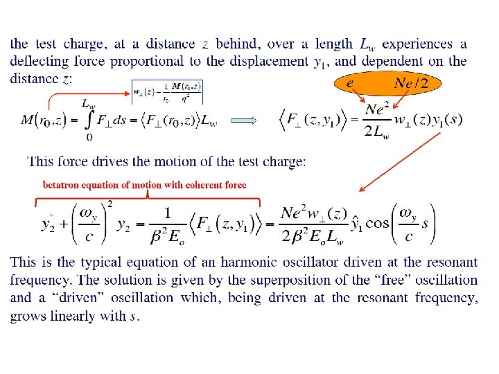

continuos growth At the end of the LINAC of length LL, the oscillation amplitude is grown by :

OUTLINE • • Heuristic model Basic Concepts Beam Break Up in Linear Accelerators BNS damping

Balakin-Novokhatsky-Smirnov Damping The BBU instability is quite harmful and hard to take under control even at high energy with a strong focusing, and after a careful injection and steering. A simple method to cure it has been proposed observing that the strong oscillation amplitude of the bunch tail is mainly due to the “resonant” driving. If the tail and the head move with a different frequency, this effect can be significantly removed. Let us assume that the tail oscillates with a frequency y+ y , the equation of motion reads:

the solution of which is:

by a suitable choice of y, it is possible to fully depress the oscillations 1 of the tail. Exploit the energy spread across the bunch which, because of the chromaticity, induces a spread in the betatron frequency. An energy spread correlated with the position is attainable with the external accelerating voltage, or with the wake fields.

More general model including charge distribution and acceleration

A. W. Chao - Physics of collective beam instabilities in high energy accelerators - Wiley, NY 1993 A. Mosnier - Instabilities il Linacs - CAS (Advanced) - 1994 L. Palumbo, V. Vaccaro, M. Zobov- Wakes fields and Impedance CAS (Advanced) - 1994 G. V. Stupakov - Wake and Impedance - SLAC-PUB-8683 K. L. F. Bane, A. Mosnier, A. Novokhatsky, K. Yokoya-Calculations of the Short Range Longitudinal Wakefields in the NLC Linac EPAC’ 98 M. Ferrario, M. Migliorati, L. Palumbo - Wake Fields and Instabilities in Linacs - CAS (Advanced) -


- Slides: 48