Inspection of Concrete Bridges Bridge Inspection Systematic observation

Inspection of Concrete Bridges

Bridge Inspection Systematic observation of condition and behaviour of various components/ parts of a bridge

Inspection Includes Going to the bridge ¡ Seeing the bridge with an eye of the Doctor (Engineer) with unaided as well as an aided eye. ¡ Systematic observation over a period of time ¡ “Thok baja ke dekhna” ¡

Objectives of Inspection • • To know whether the bridge is structurally safe Will it continue to be safe • • Identify actual and potential sources of trouble at earliest possible stage To record systematically and periodically the state of the structure To decide about the repair measures to be taken To provide feedback to the designer and the construction engineers on those features which give maintenance problems

Current Scenario on IR Concrete bridges increasing with time ¡ Advantage of ballasted deck ¡ Concrete – a heterogeneous material ¡ Durability depends on many factors ¡ Affected by environmental factors ¡

A Statement - may be controversial ¡ ¡ Concrete structures are inherently durable as compared to steel as long as they are rationally designed and constructed Deterioration of concrete is but a result of wrong concrete mix or poor construction work quality control.

But… ¡ Possibility of mistakes to happen during construction is far greater than the steel because l Most of the material of a concrete structure are supplied and assembled on site.

Therefore… the examples and anomalies and defects on concrete structure, resulting from poor quality of construction or material are numerous in number and kind. ¡ The possibility for mistakes of the type is even higher in PSC girders, where additional processes such as prestressing, grouting and erection of girders are necessary. ¡

and… There are certain phenomenon in concrete that occur in the inside and some which occur on the outside and thus some can be seen and some get manifested in the form of surface defects over the years. ¡ The behaviour of those defects is not easily predictable and analysable. ¡ Mostly it would be in the form of cracks ¡

So in concrete it becomes important to To find for cracks, which in the initial stage ¡ study them with a view to ascertain their cause ¡ Track their growth and movement ¡

How to inspect? ¡ ¡ ¡ Decide number of spans to be inspected each day Scrutinize the previous years inspection notes Try to have plan, drawings and other details of the important bridges Go through the drawings (important bridges to identify critical locations) Plan any special inspection equipment, temporary staging etc. (like tunnel inspection) Don’t rush to complete – done once a year

Precautions Clothing ¡ Glasses ¡ Shoes ¡ Scaffolding and ladders ¡ No short cuts please ¡ Watch your steps and your ego too ¡
 will inspect before")
Inspections – Open Line ¡ ¡ ¡ Para 1101 SE (Works) will inspect before monsoon every year. Para 1103 AEN open line will inspect after monsoon every year. Para 1104 (1)(a) Important bridges and bridges that call attention by DEN/Sr. DEN
 will inspect all RCC, PSC and Composite")
Inspection- Bridge Organization Para 1102 SE (Br) will inspect all RCC, PSC and Composite girders within one year of installation ¡ Para 1102 SE (Br) will inspect all these girders once in five years on planned basis ¡ SE (Br) will measure camber of PSC girders once a year with any reliable method ¡ Para 1105 AEN (Br) shall test check 10% of the bridges inspected by the bridge inspector ¡
 When signs of weaknesses discovered during routine or detailed inspection")
Special Inspection (Need based) When signs of weaknesses discovered during routine or detailed inspection or by any other observation. ¡ When the bridge loading is to be increased due to revised or increased loading standard. ¡ Distressed bridges. ¡ Exceptional events like fire, earthquake, heavy floods etc ¡

What to take along? 1. 2. 3. 4. Pocket tape (3 or 5 m long) Chipping hammer Plumb bob Straight edge (at least 2 m long) 5. 30 metre steel tape 6. A set of feeler gauges (0. 1 to 5 mm) 7. Log line with 20 kg lead ball 8. Thermometer 9. Probing rod 10. Wire brush 11. Mirror ( 10 x 15 cm) 12. Magnifying glass (100 mm dia. ) 13. Chalk/water poof pencil/pen or paint (Anne. 11/15 of IRBM) 14. Centre punch 15. Callipers (inside and outside) 16. Torch light (5 cell) 17. Paint and paint brush for repainting areas damaged during inspection 18. Gauge-cum-level 19. Piano wire 20. 15 cm steel scale 21. Inspection hammer (350450 gm) 22. Microscope 23. Binoculars 24. Camera 25. Crack meter 27. And common sense

What to Inspect … but before that ¡ ¡ Work through a checklist prepared for the particular type of structure. Should be familiar with the details of the structure and as to how it is intended to function. Should study previous reports before conducting inspection, so that the condition of the defects noticed earlier could be checked. Should be aware of rectification work done earlier, the same should be inspected and its performance should be recorded.

…and the most important ¡ thing is to know and realize that every deterioration has a cause and the aim of inspecting official is to determine that cause

Routine Inspection by AEN Purpose ¡ ¡ ¡ Whethere is any defect in structure? If yes, what is the degree of the defect? l Is it progressing? l Is it affecting the function of the structure? Is there any change in the environment? l Heavy rains. l Other factors like trespassing and other usage Is it going to affect the train operation? Is there a necessity of doing preventive work? Does it require detailed inspection?

What to see? Cracks ¡ Texture of Concrete ¡ l l Wear and erosion of concrete Leaching of chemicals Stains such as corrosion in steel, dampness, growth of algae, marine microbes Painting coat condition Bearings ¡ Camber ¡ Other observations ¡

What to see? Cracks ¡ Texture of Concrete ¡ l l Wear and erosion of concrete Leaching of chemicals Stains such as corrosion in steel, dampness, growth of algae, marine microbes Painting coat condition Bearings ¡ Camber ¡ Other observations ¡

Cracks? ¡ Cracks identification l l l Length Size Orientation Location Breathing of not Accompanying stains

Crack meter Least count 0. 02 mm Measuring Magnifier - Proceq

Cracks? Cracks need to be analysed and then only conclusions may be drawn ¡ All cracks lead to durability problems ¡ Some cracks are not serious ¡ l ¡ Other cracks are serious l l ¡ Require only covering Affect load carrying capacity Require retro-fitment as well as covering to prevent corrosion Tell tales help in decision making

Tell tales

Types of Cracks and spalling ¡ ¡ ¡ Fresh concrete Hardened Concrete Structural Cracks l l l ¡ Corrosion l l ¡ Due to loads Compatibility cracks Due to Detailing Steel Concrete Others l l Alkali-aggregate reaction Sulphate attack

Cracks in fresh Concrete Crazing ¡ Plastic Shrinkage ¡ Drying Shrinkage ¡ Plastic settlement ¡ Long term Drying Shrinkage ¡ Thermal expansion/contraction ¡ Settlement of formwork ¡

Crazing ¡ Probable Area l ¡ Probable Locations l ¡ l Impermeable formwork, over trawling Rich mixes, poor curing Remedy l ¡ Fair faced slabs Cause l ¡ Against formwork or surface Improve curing and finishing Time of Appearance l 1 -7 days, sometimes later

Plastic Shrinkage

Plastic Shrinkage ¡ Probable Area l ¡ Probable Locations l ¡ l Rapid early drying Low bleeding and fast surface evaporation Remedy l ¡ RCC slabs Cause l ¡ Random over reinforcement mesh, Diagonal, Normal to wind direction Improve early curing and trowel Time of Appearance l Thirty min. to six hours

Plastic Settlement

Plastic Settlement ¡ Probable Area l ¡ Probable Locations l ¡ l Excess Bleeding Rapid early drying Remedy l l ¡ Deep sections, Top of Columns/ troughs Cause l ¡ Over reinforcement, Arching, Change of depth Reduce Bleeding Reverberate mildly Time of Appearance l Ten min. to three hours

Early Thermal Expansion and Contraction ¡ Probable Area l ¡ Probable Locations l ¡ l Excess heat generation, Excess temp. gradient Rapid cooling, Curing by cold water Remedy l ¡ Thick walls, Thick slabs Cause l ¡ External/ Internal restraint Reduce heat and/or insulate, cool concrete, reduce spacing of steel Time of Appearance l One day to 2 -3 weeks

Long term drying shrinkage ¡ Probable Area l ¡ Probable Locations l ¡ l Absence of movement, inefficient joints Excess shrinkage, Inefficient curing Remedy l ¡ Thin walls, Thin slabs Cause l ¡ - Reduce w/c ratio, Improve curing Time of Appearance l Several weeks or months

Action in case of cracks in Fresh Concrete For purely surface cracks, normally no action taken if appearance is not an issue ¡ In case cracks are wider and deeper, the repair method as suitable may be decided based on the crack size. ¡ In case of time dependent crack like shrinkage and settlement – the action should be delayed if not affecting the structure. ¡

Cracks in Hardened Concrete during service

Compatibility cracks REINFORCED CONCRETE BEAM UNDER LOAD

Crack in the deck slab Location Bottom surface of the deck slab in the middle Reason Compatibility cracks Excessive load on the deck

Compatible Cracks ¡ Cracks which occur in course of normal loading in RCC components for reinforcement to take the tensile stresses. Specified in Para 10. 2. 1 (a) of CBC. Environment Moderate Severe Extreme Design Crack Width (mm) 0. 25 0. 20 0. 10*

STRUCTURAL CRACKS Slabs

RCC Slab Location Reason Diagonal cracks near Excessive shear force support and 1 m to 2 m from support

Cross cracks in center Location Reason Center of span Excessive Load Less reinforcement or location of reinforcement Shrinkage cracks (rare) Less Cover

Longitudinal cracks at bottom Location Longitudinal cracks on lower surface of girder Reason Shortage of distribution reinforcement Less cover to main bars Corrosion of main bar

Cross cracks at ends Location Transverse cracks on upper surface of girder Reason Shortage of bent up or top bars in upper area Drying Shrinkage

Crack near the support of cantilever Location Longitudinal cracks on upper surface of cantilever Reason Excessive load on cantilever Less reinforcement in cantilever Main reinforcement in cantilever placed lower

STRUCTURAL CRACKS Girders

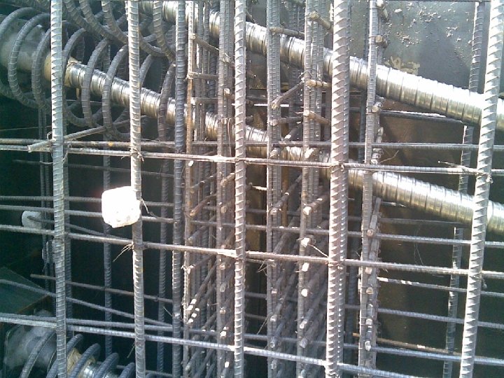
What to inspect in concrete bridges – Major Bridges – PSC girders ¡ All the items what are there in the small spans ¡ In addition Items related to pre-stressing (post tensioning) and Anchorage Zone l Slab, diaphragms, Junctions of cast in situ and precast units or RCC/PSC l Inside of the Box girder l Bearings and Expansion arrangements l

PSC Box Location Perpendicular to girder on the lower surface of the girder Reason Shortage of Pre-stressing force Excessive Load Breakage of PSC strand

PSC Box Location Perpendicular to girder on the upper surface of the girder Reason Overstressing of girder Shortage of loading Closes during passage of train

PSC Box Location Reason Diagonal Cracks Shear stress due to near the support loading Drying Shrinkage

Structural Cracks

Structural Crack

What to inspect in concrete bridges – Major Bridges – PSC girders ¡ All the items what are there in the small spans ¡ In addition Items related to pre-stressing (post tensioning) and Anchorage Zone l Slab, diaphragms, Junctions of cast in situ and precast units or RCC/PSC l Inside of the Box girder l Bearings and Expansion arrangements l

Anchorage Zone • Maximum stresses during stressing operation • Concrete strength increases with age • Losses in Pre-stress increases with time • So, in no case there can be distress after the initial period • If there is some cracking it has to be from the time of construction
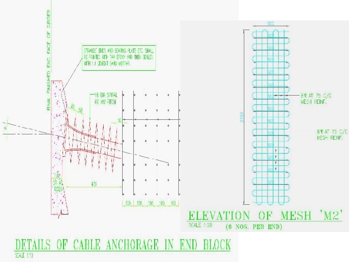
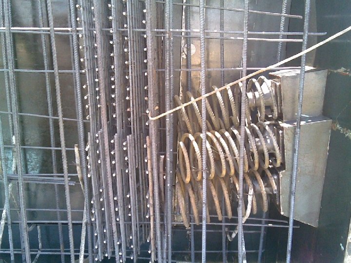

Bursting Cracks in anchorage area

What to inspect in concrete bridges – Major Bridges – PSC girders ¡ All the items what are there in the small spans ¡ In addition Items related to pre-stressing (post tensioning) and Anchorage Zone l Slab, diaphragms, Junctions of cast in situ and precast units or RCC/PSC l Inside of the Box girder including drainage inside the Box Girder l Bearings and Expansion arrangements l

Diaphragm and cast-insitu deck or RCC/PSC Location At the interface of the precast I – Girder and the diaphragm as well as deck slab Reason Differential shrinkage between the elements cast at different time Mishandling during lifting

Structural crack in diaphragm

Crack at the junction of web and the slab Location At the junction of the web and the slab Reason Construction joint, no crack Relative movement due to shear between the box and slab

What to inspect in concrete bridges – Major Bridges – PSC girders ¡ All the items what are there in the small spans ¡ In addition Items related to pre-stressing (post tensioning) and Anchorage Zone l Slab, diaphragms, Junctions of cast in situ and precast units or RCC/PSC l Inside of the Box girder l Bearings and Expansion arrangements l

Cracks around blisters Crack at the front of the blister – due to prestressing force

What to inspect in concrete bridges – Major Bridges – PSC girders ¡ All the items what are there in the small spans ¡ In addition Items related to pre-stressing (post tensioning) and Anchorage Zone l Slab, diaphragms, Junctions of cast in situ and precast units or RCC/PSC l Inside of the Box girder l Bearings and Expansion arrangements l

Structural Crack over bearing

Poor expansion arrangements If the girder not free to expand, stresses will build up. ¡ Can cause cracks near the expansion arrangement ¡ Choking by ballast in the expansion joint will also cause problems ¡

Cracks due to detailing defects

Horizontal crack in the web

Cracks Due to Corrosion ¡ Corrosion of the steel l ¡ Corrosion Phenomenon Carbonation of concrete Volume increase on corrosion Alkali aggregate reaction

Electrochemical corrosion ¡ ¡ Iron reacts as Fe >> Fe++ + 2 e- (Anode process) Water takes oxygen from Atmosphere 2 H 2 O + O 2 + 4 e- >>> 4 OH- (Cathode Process) Fe++ and OH- creates Fe(OH)2 is not stable, oxidizes to form Fe(OH)3 ¡ Takes water to form Fe(OH). 3 n. H 2 O (Rust)

Electrochemical corrosion
2 Fe(OH)3 n. H 2 O")
Corrosion of Steel Fe Fe 3 O 4 Fe(OH)2 Fe(OH)3 n. H 2 O 1 2 3 Volume 4 5 6

Corrosion of Steel ¡ Probable Area l ¡ Probable Locations l ¡ l Lack of cover and dampness, Carbonation, Chlorides Poor quality concrete Remedy l ¡ Alternate drying and wetting, humidity Cause l ¡ Natural and slow, fast if Ca. Cl is present Use dense concrete (Portland Blast Furnace Slag cement), Dehumidify, Cathode protection Time of Appearance l More than two years
2 + 2 CO 3 > Ca. CO 3 +")
Corrosion of Concrete. Carbonation Ca(OH)2 + 2 CO 3 > Ca. CO 3 + 2 H 2 O 3 Ca. O • 2 Si. O 2 • 3 H 2 O + 3 CO 2 > 3 Ca. CO 3 • 2 Si. O 2 • 3 H 2 O ¡ The p. H-value decreases to less than 9, which normally is insufficient to protect the reinforcement against corrosion.

Corrosion of Concrete. Carbonation X= K T ½ ¡ Where X is measured in mm and T in years ¡ K is function of concrete strength ¡ Above relation is for RH 50%

Corrosion of Concrete. Carbonation

Depth of Carbonation – Strength of Concrete

Alkali Aggregate Reaction ¡ Probable Area l ¡ Probable Locations l ¡ Reactive silicates and carbonates in aggregates reacting with Alkali in cement Remedy l ¡ Damp area, shows gel type or dried resin type deposit in cracks Cause l ¡ - Use proper aggregates, Use Portland Blast Furnace Slag cement, Keep water away Time of Appearance l More than five years

Alkali Aggregate Reaction

Sulphate Attack ¡ ¡ ¡ Sulphate salts from surrounding soil react with C 3 A. No deposits like those in Alkali. Aggregate reaction Use low C 3 A cement, Portland Blast Furnace Slag cement After two years or so
 +")
Sulphate Attack ¡ ¡ High concentrations of sulphate ions (SO 4 - -) + Ca(OH)2 + 2 H 2 O -> Ca. SO 4. 2 H 2 O + 2 OH- + expansion Low Sulphate ion concentration Calcium Aluminate Hydrate + Ca. SO 4. 2 H 2 O -> ¡ 3 Ca. O. Al 2 O 3. Ca. SO 4. 32 H 2 O (ettringite) +expansion Magnesium and Ammonium Sulphate(Serious) Mg. SO 4 reacts with Calcium Aluminate Hydrate Mg. SO 4 + Ca(OH)2 -> Ca. SO 4 + Mg(OH)2 + volume expansion

What to see? Cracks ¡ Texture of Concrete ¡ l l Wear and erosion of concrete Leaching of chemicals Stains such as corrosion in steel, dampness, growth of algae, marine microbes Painting coat condition Bearings ¡ Camber ¡ Other observations ¡

Texture of Concrete ¡ ¡ ¡ Possibility of a leakage, chemical attack by softening, leaching Sulphate attack - whitening of the concrete. Rust stains may indicate the corrosion of reinforcement/pre-stressing steel. In fire damaged structure, the colour of the concrete gives an indication of the maximum temperature reached. Wear and tear of concrete surface Defects like honeycombing, marine growth etc.

Leaching of chemicals

Corrosion stains on concrete surface

Corrosion stains on concrete surface

Corrosion in reinforcement bar

Spalling of concrete

Spalling on concrete surface

Honeycombed concrete

MARINE GROWTH

Worn out concrete surface

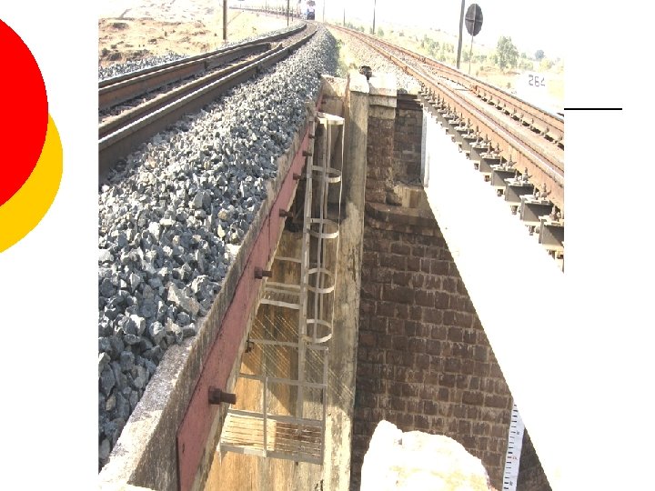
Damage to the surface of deck slab ¡ Girder flooring can get worn out with constant use l Also if the concrete quality is not good Once wearing coat gets eroded and then the girder will start wearing out ¡ Check under the ballast once in five years ¡ Tell tale sign: water leaking from the deck slab ¡

WEARING COAT STRUCTURAL CONCRETE SECTION Formation of depressions due to absence of wearing coat 1. The condition of deck top should be checked after removing ballast at sample locations 2. The drainage of the deck should be clear 3. If damage is there, will affect the life of the structure

Water leakage

Water leakage

Dampness

Drainage in Box culverts • • In case there is some leakage from the deck slab, the water should be able to drain out otherwise it will affect the durability of the bottom slab of the Box These drainage spouts should be checked Drainage in the bottom slab 109

What to see? Cracks ¡ Texture of Concrete ¡ l l Wear and erosion of concrete Leaching of chemicals Stains such as corrosion in steel, dampness, growth of algae, marine microbes Painting coat condition Bearings ¡ Camber ¡ Other observations ¡

Bearings Cleanliness around bearings ¡ Seating of girder on bearing ¡ Seating of bearing on pedestal ¡ Movement of the girder: actually measured vis-à-vis theoretical calculations ¡ Tell-tale signs of overstressing or locked up movement around the bearings ¡

Pot – PTFE bearings ¡ What to inspect? l Movement during peak winter (early morning) and peak summer (afternoon) ¡ l l Compare the movement along with temperature with design values Measure dimensions to ascertain excessive stress or strain Evidence of any locked up or jammed condition Corrosion Adjoining areas of bearing for trouble

Neoprene bearings ¡ What to inspect? l l l Titling Bulging Tearing Excess vibrations (soft bearings) Adjoining areas of bearing for trouble

Bulged Bearing

Tilted Bearing

Torn Bearing

Crack in Pedestal

Crack at the junction of cast-insitu end portion in PSC girders

What to see? Cracks ¡ Texture of Concrete ¡ l l Wear and erosion of concrete Leaching of chemicals Stains such as corrosion in steel, dampness, growth of algae, marine microbes Painting coat condition Bearings ¡ Camber ¡ Other observations ¡

CAMBER Unlike steel bridges the camber loss in the PSC bridge would not be without attendant warnings. ¡ Camber loss in PSC would result in ¡ l l ¡ Excessive cracking on the bottom surface of Box girder or I-girder Separation cracks between the deck slab and the I-girder. Stipulation for annual measurement of camber

Camber ¡ Camber – Parameter showing overall health of the girder l ¡ Linked to the efficiency of the pre-stressing force Nominated points chosen for recording l l Smaller spans: Mid span, end of span. Longer Spans: Quarter spans also Nominated point marked by steel or ceramic plates fixed with epoxy ¡ Record carefully and accurately ¡
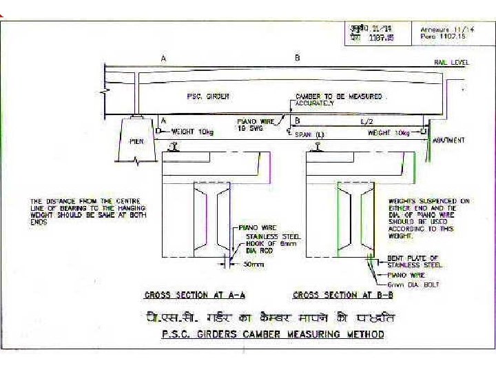

CATENERY WIRE METHOD
 Mid - Span mm 10 Kg 18 SWG Wire")
Deflection of catenary (piano wire) Mid - Span mm 10 Kg 18 SWG Wire 10 Kg Dia. of Wire (18 SWG) = Ф = 1. 219 mm Length of wire (Clear span) = L = 16 m (Roughly) Tension on either end = T = 10 Kgf (counter wt) Self wt of wire/unit length (w) = (π Φ 2/4) 7. 850/1000 = 0. 00917 Kg/m Deflection @ Mid-Span ( ) = w. L 2/(8 T) Where T is the Tension in wire, = 0. 00917 x 16 2 /8 x 10 = 0. 029 m i. e. , 29 mm

Laser range meter R 2 R 1 R 3 Laser Meter Levelling instrument Camber at Mid-Span = R 1 – {R 2 + R 3}/2 LASER - Light Amplification by Stimulated Emission of Radiation

Laser Range Meter

Laser Range Meter

PD 32 Laser range meter Dimensions 120× 65× 28 mm Weight without batteries : 220 g Measuring Range : 0. 05 to 70 m without target plate, up to 200 m with PDA 50 target plate Accuracy : ± 1. 5 mm Operating temperature range – 10°C to +50° C Measuring functions : Single and continuous measurement of areas and volumes. Calculation function : +, -, x, / and special geometrical functions Laser : 635 nm, class 2 (IEC 825 -1), class II (FDA 21 CFR) Operating Time with 2 AA-size Batteries : Up to 15, 000 measurements.
 CATENERY WIRE METHOD -L 1 – 0 mm, L 2 –")
Trial results 1) CATENERY WIRE METHOD -L 1 – 0 mm, L 2 – 40 mm, L 3 – 0 mm Camber = 40 mm - 29 mm (Deflection of Catenary) = 11 mm 2) INVERT LEVEL METHOD -L 2 - 2. 070 m, L 1 - 2. 080 m, L 3 - 2. 080 m Camber = 5 mm 3) LEVELING AND LASER RANGE METER -L 2 - 1. 944 m, L 1 - 1. 950 m, L 3 - 1. 939 m Camber = 8. 5 mm

What to see? Cracks ¡ Texture of Concrete ¡ l l Wear and erosion of concrete Leaching of chemicals Stains such as corrosion in steel, dampness, growth of algae, marine microbes Painting coat condition Bearings ¡ Camber ¡ Other observations ¡

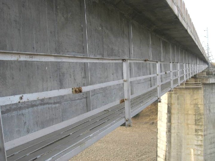
Inspections – Misc. items Excess vibrations ¡ Ventillation arrangement ¡ Ancillary arrangements such as ladders, railings ¡ Hitting of girders by road/ water borne vehicles ¡ Other miscellaneous observations including trespassing ¡ Bridge board ¡ HFL/Danger level ¡ Flood height gauge ¡

Girder hit from below

HOW TO INSPECT?

How to inspect?

Inspection arrangement for PSC girders Permanent arrangement such as Cradles, ladders, walkways etc. ¡ Temporary arrangements such as ladders, challis etc. ¡ Mobile rail mounted inspection arrangement ¡ l Few purchased by the railways
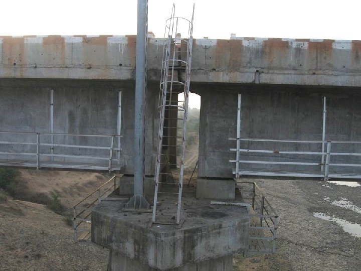

Inspection platform for piers/ abutment

Sliding Platform

Steel cradles

Mobile crane being procured for inspections

R: DEPTH BELOW RAIL LEVEL: 12 M S: HORIZONTAL RANGE: 9 M T: MAXIMUM WORKING HT ABOVE RAIL LEVEL: 8 M a: HORIZONTAL REACH OF PLATFORM: 7. 5 M ROTATION OF PLATFORM ABOUT VERTICAL AXIS 1800 TO 3600

Inspection using crane in progress

Inspection using crane in progress

Defects Identified Technical solution to the defect ¡ Flow of stresses to govern the repairs. Durability aspects important. ¡ If RDSO standard drawing, RDSO to be involved in the rehabilitation. ¡

Defects Identified Action to be taken as per the paras 503 509 of IRBM on any defects ¡ Analogous locations to the defect on the same girder, and in other girders on the same bridge or other bridges on the system to be inspected in detail ¡ Efforts for identification of reasons for the defect. Repair (covering up) not to be the immediate goal. ¡

Distressed Bridges A distressed bridge is the one which shows physical signs of deterioration, indicating need for rehabilitation through special repairs, strengthening or rebuilding (including replacement of girders) ¡ If defects are noticed ¡ l l Inspect thoroughly Impose suitable SR, including suspend traffic, if warranted

Distressed Bridges ¡ ¡ Tell tales on defects Detailed report to divisional office l l ¡ Sr. DEN/DEN to declare distressed after personal inspection Report to be sent to HQ/ RDSO Categories l l I: Needs rehabilitation on immediate basis, say within a year’s time II: Under observation, to be rehabilitated on program basis

Distressed Bridges ¡ ¡ All distressed bridges may not need SR As a general guidance: l l Group I: SR 15 KMPH ¡ Settlement of foundations, deep scour around piers, cracks in main members, wide cracks in piers/ abutments etc Group II: SR 25 to 50 KMPH ¡ Cracks in return/ wing walls, spalling of concrete, slight leaning of spandrel wall, abutment, loose rivets, excess vibrations etc

Distressed Bridges ¡ ¡ ¡ Divisions shall maintain details of distressed bridge Railways shall have distressed bridge diagram as per Annex 5/1 Inspection of distressed Bridges:

References ¡ ¡ Indian Railways Bridge manual IRICEN book on “Bridge Inspection and Maintenance” RDSO report BS-48 – Inspection, Maintenance and Rehabilitation of Concrete Bridges RDSO report BS-63 – Causes, Evaluation and repairs to cracks in concrete

Few Case Studies Based on RDSO B & S Reports
")
3 RD GODAWARI BRIDGE NEAR RAJMUNDRY (BS-81)

The structure ¡ ¡ ¡ Span 94 m Twin Bow string RCC arch connected by precast RC struts in lateral direction 12 pairs of vertical Dina Hangers comprising 49 wires of 7 mm dia PSC box tie girder – 16 cables each comprising of 61 wires of 7 mm dia 12 cross tie beams in the girder connecting the columns hanging from Dina hangers

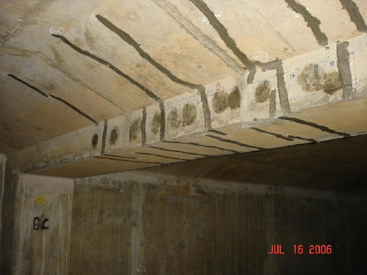
The problem Cracks on the tie beam inside the box girders connecting the columns carrying the load from the suspenders ¡ Maximum width of cracks is 0. 06 mm ¡ All other parameters found OK ¡ Cracks are not found to be active under train loads ¡ Crack width is within the limit given in CBC. No cause for worry ¡

Bridge No. 73 – Vasai Creek 28 span of 48. 5 m

Problem ¡ ¡ ¡ Longitudinal Cracks on the inside of the web of the Box Girders (9 and 5 on West and East side to 8 and 12 in 2004) Width of crack varying from 0. 08 mm to 0. 40 mm Longest crack 19 m long (34. 11 m in 2004 by joining of two cracks) Some fine cracks seen on the outside web of the Box Girders Diagonal cracks on the end block passing through the vent hole

Sketches

Sketches
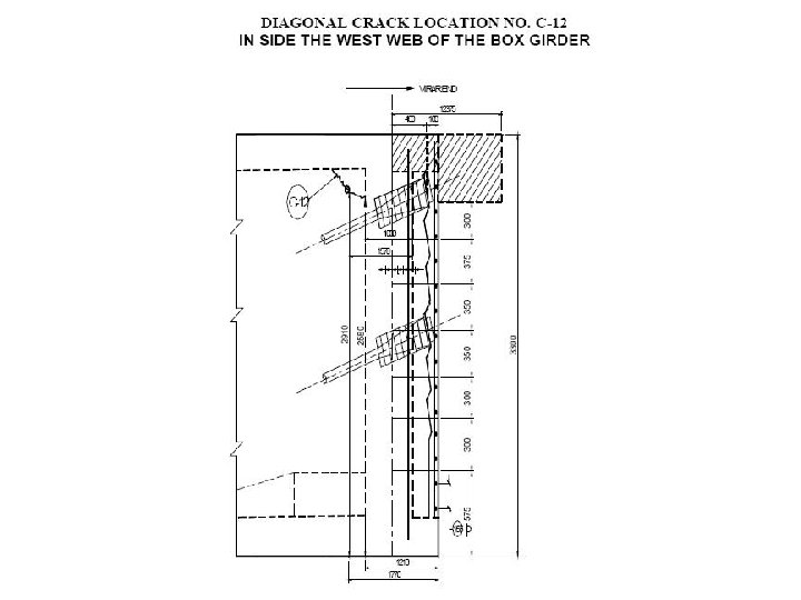

Current Situation Not much progress in the cracks ¡ SR of 90 Kmph ¡ RDSO studied thrice ¡ IIT Mumbai did modeling in 3 -D and has recommended that only local trains be allowed on the bridge ¡

Be Careful


What to see? Summary All Over Anchorage zone ¡General Condition ¡Condition of surface coating ¡Cracks ¡Corrosion signs, efflorescence, rust streaks ¡Scaling/ spalling ¡Construction joints, drainage, ladders etc ¡Cracks ¡Rusting ¡Condition of cable end sealing

What to see? Top and Bottom deck slab ¡Cracks, Delamination, scaling ¡Drainage, seepage, leaching ¡Worn out wearing coat, abrasion damage ¡Damage due to accidents etc Support points of bearing and bottom of girder immediately ¡If seating of girder is uniform ¡Condition of anchor bolts ¡Spalling/ crushing/ cracking around bearing support

What to see? Drainage Spouts ¡Clogging and physical condition ¡Adequacy of projection of spout on the underside Joints in segmental construction Expansion Joints ¡Cracks, corrosion signs ¡If joint is free to expand/ contract ¡Sealing Material l. Hardening/ cracking in Bitumen l. Splitting/ oxidation/ Creep/ flattening/ bulging in elastomer

What to see? Top and ¡Spalling/ cracking/ scaling Bottom flange ¡Rust streaks along cables/ of I – girder reinforcement Bottom slab in BOX girder ¡Spalling/ cracking/ scaling ¡Rust streaks ¡Drainage Webs ¡Cracks, Diaphragms ¡Cracks corrosion at junctions with PSC ¡Diagonal cracks at corners ¡Cracks around opening

What to see? Expansion Joints ¡Condition of sliding plates l. Corrosion, ¡Debris condition of weld in joint ¡Check for alignment, distortion ¡Falling debris Bearing (General) ¡Check if free to rotate/ move ¡Check for even seating ¡Check for load sharing between bearings ¡Physical condition ¡cleanliness

What to see? Metallic Bearing Elastomeric Bearings ¡Rusting/ corrosion ¡Condition of grease ¡Condition of anchor bolts ¡Unusual tilt of rollers ¡Rollers jumping off guides ¡Flattening, bulging ¡Splitting/ tearing ¡Non uniform thickness ¡Displacement

What to see? General ¡Trespassing by vehicles, passersby etc and resultant damage, if any ¡Ladders, inspection arrangements etc are OK or not. ¡Ballast retaining wall ¡General observations under train movement i. e. excess vibrations, excess deflection, odd sounds or ay other abnormal behaviour.
- Slides: 162