INO MAGNET M S Bhatia LPT Division B

INO MAGNET M. S. Bhatia L&PT Division, B. A. R. C. …UP TO NOW and THE ROAD AHEAD…

The beginning … • To understand the need and translate into the design variables that meet the objectives as best as possible keeping in mind the constraints at hand. • Interact with the other groups to realize a design that achieves maximal overlap between physics objectives while maintaining optimality in engineering.

The purpose… • The magnet is to provide the target nuclei for interaction (50 k. Ton to 100 k. Ton) in 3 to 6 modules. • Together with the layered detectors, the ICal arrangement shall provide adequate resolution towards calorimetry.

Physics-magnet interface • The size and aspect ratio of each module • The plate thickness and dimensions • The size of coils and their location for efficient magnetization, best uniformity and minimal complexity in track simulations especially in regard to field direction changes

The work plan • Physics requirement from ICAL detector: Identification of muon charge, momentum piecewise uniform B 1. 3 Tesla • To create a facility for 3 D simulation of magnet designs. • To build a small-scale proto-type • To conduct engineering studies for efficient scale-up • To incorporate the findings in final design of full scale ICAL Magnet
 • To find vendors for material input • To find")
The work plan (contd) • To find vendors for material input • To find vendors for fabrication of magnet body and coils • To plan a stage wise deployment of magnet at the INO site.

3 D Simulation • We compared available FEM based codes- ANSYS, TOSCA, MAGNET… and chose Magnet 6. 0 by M/s Infolytica, Canada. Now we have upgraded to Magnet 6. 26. • The choice was made on issues like ease in problem definition, meshing accuracy, post processing features, data display and user friendliness. • The coupling to other codes for evaluation of thermal and mechanical parameters was not given high priority. • This software has been in use for more than two years now and is the backbone of our simulation work…

ICAL proto-type simulation number of plates = 13 dimension of 'C'(2480 X 1560(960 X 600)) dimension of 'T'(2480 [640+1200+640]X 1560[600+960]) current = 500 amp X 10 turns

Field in the center plate with various gaps between C and T plates

Why ICAL proto-type magnet? • To provide a proof of principle working model (muon detector). • To provide information to bridge gaps between simulation and actual. • To provide an active area of 1 m × 1 m for RPCs in a 13 layer structure. • A good training ground for future trainees.

Steel for proto-type magnet MHD Magnet BARC-BHEL, Trichy
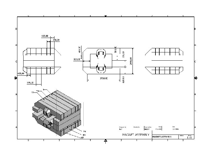

The proto-type magnet C and T Sections
 GAP 2 (mm) GAP 3 (mm) GAP 4 (mm) At ‘C’side")
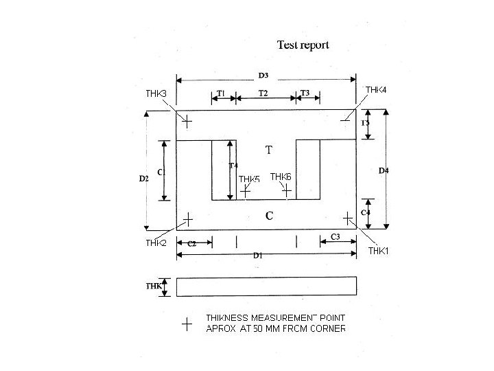
GAP 1 (mm) GAP 2 (mm) GAP 3 (mm) GAP 4 (mm) At ‘C’side At ‘T’side C 1 T 1 -C 2 T 2 52. 1 52 51. 46 51. 8 C 2 T 2 -C 3 T 3 52. 1 51. 26 50. 6 51. 56 C 3 T 3 -C 4 T 4 52. 38 51. 58 52. 26 52. 2 C 4 T 4 -C 5 T 5 52. 28 52 51. 78 53 C 5 T 5 -C 6 T 6 51. 46 51. 8 52. 92 51. 5 C 6 T 6 -C 7 T 7 52 52. 48 51. 78 52. 36 C 7 T 7 -C 8 T 8 51. 3 51. 58 53 51. 78 C 8 T 8 -C 9 T 9 52. 4 52. 58 51. 1 51 C 9 T 9 -C 10 T 10 52 52. 16 52. 62 51. 36 C 10 T 10 -C 11 T 11 51 52. 4 51. 28 C 11 T 11 -C 12 T 12 52. 52 51. 6 52. 8 C 12 T 12 -C 13 T 13 52. 3 51. 58 52. 92 52. 56 Readings for the plate thickness in gaps measured in the stack after total assembly of 13 C and T forms

The proto-type magnet

The proto-type magnet
")
Effect of material on magnet excitation (simulation incl. no air gap)

COMPARISON OF SIMULATION WITH GAPS AND MEASURED DATA
 Material characteristics. Physical gaps")
Simulation against actual… • • Simulation parameters (air gap, meshing…) Material characteristics. Physical gaps between plates. Physical mismatch between plates (thickness, planarity, shape distortions (waviness etc. ) • Thermally affected areas around cut surfaces

EFFECT OF COIL FIELD

NEED FOR CALIBRATION • We have initiated discussions with NPL Delhi to get our instruments calibrated against the secondary standards available in our country. • The situation does not appear to be very rosy on this front as magnetic field activity on industrial scale is not widespread. • We may need outside help on this front.

Engineering studies… • Material studies … exploit the composition/ magnetic characteristics relation in soft iron steels. We have procured a B-H curve tracer for macroscopic sample testing.

Engineering studies… Test results: SAIL low C steel sample #2

B-H curve for Tata A-grade sample Mean path length of coil: 20. 169 cm Area of cross section: 2. 895 cm 2 No. of primary turn: 50, No. of secondary turn: 10 Saturation magnetic flux density, BS = 17. 19 k. Gs at 10 A DC
")
B-H curve for Japanese sample (waterjet cut)
")
B-H curve for Japanese sample (CNC machined)
")
B-H curve for Japanese sample (waterjet cut)
")
B-H curve for Japanese sample (CNC machined)

Engineering studies… • Interaction with steel mill that rolls out iron plates to ascertain data on tolerance in plate dimensions, thickness and planarity. (show video) • To explore the options in cutting methods used for plate sizing. • To explore possibility of orienting the grains after roll out.

Engineering studies… Developing local vendors to prepare large samples of low carbon steel cut by : Laser Underwater plasma torch Water jet Wire cutting Gas cutting to evaluate the cut surface for transmission of magnetic flux with minimal loss and minimal post machining.

Waterjet cutting machine Closeup of cut samples

Engineering studies… • The preparation of base at INO site and issues connected with assembly of magnet at INO site. • Evolve a procedure for assembly that minimises pile up of mismatch in lateral and vertical direction. A contract to explore this aspect was given to TCE and they have given a detailed project report after many deliberations on salient points raised by our engineers.

Engineering studies… • Electromagnet coil design, sizing, cooling and mounting. DM water or oil ? … cooling circuit suitable for underground laboratory ? Alignment and support structure to enable minimal interference during on-site assembly.

Full scale INO Magnet * The simulation is done with commercial software Magnet 6. 26 (infolytica). Here the figure shows the 1/8 th part continuous slot model (8 X 7) of full detector(16 X 14).

Design and coordinate system of the continuous slot model. Z = 0. 048 m corresponds to central plate i. e. , from bottom , it is 76 th plate. The distance between the center of two consecutive plates is dz = 0. 096 m. Thickness of each plate (along z-direction) is 0. 056 m. Surface area (along XY- plane ) of the plate is 16 m X 16 m = 256 m 2. Plate and coil : there is a gap between plate and the coil about 10 mm along the cross sectional periphery of the coil. Dimension of the slot is {0. 01 (m) X 8 (m)}. Cross section of the coil is {0. 008(m)X 0. 0625 (m)}. Dimension of each component in the plate is {4(m)X 2(m)}.

For continuous slot magnet plates, effect of gap in steel plates (air gap in between components of same plate) 0 mm : 2 mm : 5 mm in By component (T) with 1) Total coil current 50000 Amp-turns is 1. 42(T) : 1. 31(T) : 1. 16(T). 2) Total coil current 25000 Amp-turns is 1. 17(T) : 0. 92(T) : 0. 71(T). Magnet field using low carbon steel with coil current I = 50000 Amp-turns (By = 1. 4 (T))

The arrows in the figure correspond to B- tangential. And shaded plot correspond to By. The center of the detector corresponds to z = 0. And x = 0, y = 0 at one of the edge of the plate.

The following plots corresponds to By component along the central plate of the ICAL detector. This plot on the RHS corresponds to By field on each plate along the axis (x =0, y =0).
 Plate dimensions: 16")
Two slot Four slots Material: Tata steel Model: Full (Single plate) Plate dimensions: 16 X 0. 056 m 3 No. of plate: 1 Slot Cross-section: 0. 1 X 0. 645 m 2 Coil Cross-section : 0. 08 X 0. 625 m 2 , for two and four slots model. In continuous slot model, Slot Cross-section: 0. 1 X 8 m 2 Coil Cross-section : 0. 08 X 0. 625 m 2 Coil width: 7. 82 m , Coil height: 14 m Continuous slot

Intensity variation of color pattern shows the magnetic field strength variation through out the material

Comparative study of magnetic flux density distribution at different slots model with excitation current 50000 A*t Point of observation Y=8 m, Z= 0. 028 m Uniformity of field pattern is more compare to two slots and four slots model DC
 Gap between tiles: Zero")
Material: Tata steel, Model: Full (Single plate having 32 tiles) Gap between tiles: Zero Slot Cross-section: 0. 1 X 8 m 2 , Coil Cross-section : 0. 08 X 0. 625 m 2 Tile dimensions: 4 X 2 X 0. 056 m 3 Model-1 Tile dimensions: 2 X 4 X 0. 056 m 3 Model-2

Model-1 Single plate 50000 A*t Model-2

Point of observation: Y=8 m, Z= 0. 028 m Point of observation: X=8 m, Z= 0. 028 m Strength of magnetic field unchanged irrespective of models for tiles with no gap

Tiles with different arrangement Remodel-1 Remodel-2

Comparison of magnetic flux density at different excitation current for Remodel-1 and 2 Point of observation Y=8 m, Z= 0. 028 m The non-uniformity of field pattern is due to 2 mm gap between tiles along X and Y direction

Model-2, No. of plates : 6 Each plates having 32 tiles Gap between tiles : 2 mm along x , y direction and 2 m along z direction Excitation current : 50000 A*t

Comparative study of magnetic flux density at different excitation current Model-2, No. of plates : 6 Each plates having 32 tiles Gap between tiles : 4 mm along x , y direction and 2 m along z direction, Point of observation: 4 th plate Y= 8 m , Z=1. 028 m for BY - X And X= 8 m , Z=1. 028 m for BY –Y , X= 8 m , Y= 8 m for BY-Z

Comparative study of magnetic flux density at different excitation current Model-2 No. of plates : 6 Each plates having 32 tiles Gap between tiles : 6 mm along x , y direction and 2 m along z direction Point of observation: 4 th plate Y= 8 m , Z=1. 028 m for BY - X And X= 8 m , Z=1. 028 m for BY –Y , X= 8 m , Y= 8 m for BY-Z

Gap between tiles 2 mm Gap between tiles 4 mm Gap between tiles 6 mm
 at different gap between tiles, using model-2")
Comparative study of magnetic flux density(BY- X) at different gap between tiles, using model-2 (Single plate) No. of plates: 1 Point of observation : Y= 8 m, Z= 0. 028 m The difference in magnetic flux density values decrease with increase in excitation current
 strength for tiles with different gap Exc.")
Comparative study of magnetic field (By- Z) strength for tiles with different gap Exc. Curr. 15000 A*t Exc. Curr. 25000 A*t No. of plates: 6 Point of observation: 4 th plate X=8 m , Y=8 m Exc. Curr. 50000 A*t The difference in magnetic flux density values decrease with increase in excitation current

Vendor development • Supply of 50 -100 k. Ton of low carbon steel. First meeting with GM and team at SAIL, Bhilai • Fabrication of magnet modules (16 m × 15 m × 14 m weighing ~16 kton). • Fabrication of coils for above magnets. First meeting with Patel Analog, Pune & NFTDC, Hyderabad • Transport of various finished products to the INO site. • Assembly of INO magnet in the under-ground laboratory.

We recognise… • While the general principles and design steps may be similar in magnet fabrication of different types, each type has its own share of challenges that are in a way unique to it. The INO Magnet has challenges that arise primarily due to its large size and weight.

The team: M. S. Bhatia V. M. Datar A. S. Dongare N. K. Mondal P. R. Sarma Suresh Kumar P. Verma Y. P. Viyogi VECC colleagues for Prototype ICAL installation

Thank you
- Slides: 57