Injectors FUNCTION OF DIESEL FUEL INJECTION The fuel


 • Electronic unit injectors are mechanically pressurized using electronic")


- Slides: 20
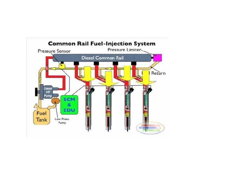
Injectors • FUNCTION OF DIESEL FUEL INJECTION • The fuel injection system lies at the very heart of the diesel engine. By pressurising and injecting the fuel, the system forces it into air that has been compressed to high pressure in the combustion chamber. • The diesel fuel injection system consists of: • fuel injection pump - pressurises fuel to high pressure • high-pressure pipe - sends fuel to the injection nozzle • injection nozzle - injects the fuel into the cylinder • feed pump – sucks fuel from the fuel tank • fuel filter - filtrates the fuel • Some types of fuel tanks also have a fuel sedimentor at the bottom of the filter to separate water content from the fuel.
• Adjusting injection timing • Ignition delay is the period of time between the point when the fuel is injected, ignited and combusted and when maximum combustion pressure is reached. As this period of time is almost constant, irrespective of engine speed, a timer is used to adjust and change injection timing – enabling optimum combustion to be achieved. • Atomising fuel • When fuel is pressurised by the injection pump and then atomised from the injection nozzle, it mixes thoroughly with air, thus improving ignition. The result is complete combustion. •
• Functions of the system The diesel fuel injection system has four main functions: • Feeding fuel • Pump elements such as the cylinder and plunger are built into the injection pump body. The fuel is compressed to high pressure when the cam lifts the plunger, and is then sent to the injector. • Adjusting fuel quantity • In diesel engines the intake of air is almost constant, irrespective of the rotating speed and load. If the injection quantity is changed with the engine speed and the injection timing is constant, the output and fuel consumption change. Since the engine output is almost proportional to the injection quantity, this is adjusted by the accelerator pedal.
INJECTORS: The fuel oil injection system for a diesel engine • • Delivering right amount of fuel: The function of the fuel injection system is to provide the right amount of fuel at the right moment and in a suitable condition for the combustion process. • There must therefore be some form of measured fuel supply, a means of timing the delivery and the atomisation of the fuel.
• • The injection of the fuel is achieved by the location of cams on a camshaft. This camshaft rotates at engine speed for a two-stroke engine and at half engine speed for a four-stroke. There are two basic systems in use, each of which employs a combination of mechanical and hydraulic operations. The most common system is the jerk pump; the other is the common rail. Injector Construction and principle A typical fuel injector is shown in Figure , It can be seen to be two basic parts, the nozzle and the nozzle holder or body. The high-pressure fuel enters and travels down a passage in the body and then into a passage in the nozzle, ending finally in a chamber surrounding the needle valve. • The needle valve is held closed on a mitred seat by an intermediate spindle and a spring in the injector body. The spring pressure, and hence the injector opening pressure, can be set by a compression nut which acts on the spring. The nozzle and injector body are manufactured as a matching pair and are accurately ground to give a good oil seal. The two are joined by a nozzle nut.
• • • The needle valve will open when the fuel pressure acting on the needle valve tapered face exerts a sufficient force to overcome the spring compression. The fuel then flows into a lower chamber and is forced out through a series of tiny holes. The small holes are sized and arranged to atomise, or break into tiny drops, all of the fuel oil, which will then readily burn. Once the injector pump or timing valve cuts off the high pressure fuel supply the needle valve will shut quickly under the spring compression force. All slow-speed two-stroke engines and many medium-speed fourstroke engines are now operated almost continuously on heavy fuel. A fuel circulating system is therefore necessary and this is usually arranged within the fuel injector. During injection the high-pressure fuel will open the circulation valve for injection to take place. When the engine is stopped the fuel booster pump supplies fuel which the circulation valve directs around the injector body. Older engine designs may have fuel injectors which are circulated with cooling water.
Common rail Injection system
Unit Injector • The unit injection system integrates the injection pump and nozzle into a single module. • This means the functions of fuel pressurization; injection timing, atomization and fuel distribution are accomplished using one single component.
Construction of Electronic Unit Injector(EUI) • Electronic unit injectors are mechanically pressurized using electronic control of governing, timing and metering functions. • A unit injector consists of several basic elements. 1. The spring-loaded plunger and barrel assembly to pressurize fuel inside the injector. 2. A poppet valve, known also as a spill control valve or solenoid needle valve that regulates the build-up of pressure inside the injector. 3. An electric solenoid or cartridge valve that actuates movement of the poppet valve or needle valve. Linkage such as a stator or solenoid pin may also directly connect the solenoid to the poppet valve in some injectors.
Construction of EUI
4. Fuel inlet and return passageways. - The fuel inlet is supplied low-pressure fuel by the transfer pump. The return passageway permits fuel which has circulated through the injector to flow back to the supply tank. Since the injector is located in the cylinder head, and pressurization of fuel creates heat, it is important that a steady circulation of fuel passes through the injector removes heat. 5. The nozzle valve at the injector tip is like a conventional nozzle valve opening at 4, 500 -psi to 5000 -psi in most injectors. This provides for improved atomization and crisp beginning and end of injection characteristics.
EUI Operating Principles • Regardless of the type of unit injector, EUI’s share common operating principles. An electrical signal is sent to the unit injector’s solenoidactuated spill/poppet valve system to deliver the correct quantity fuel at the precise time required to by ECM algorithms and fuel maps. • Injection is accomplished by switching an integrated solenoid valve on and off. Injection delivery quantity is a function of both electrical signal time and plunger velocity. T • The time or duration the injector solenoid is electrically actuated is one factor determining the injection quantity. This means the longer a signal is applied to the solenoid, the greater the quantity of fuel injected. • However, the faster the engine rotates, the greater the distance of plunger travel per unit of time. Consequently, more fuel is injected at higher engine speed if the time the solenoid is electrically actuated remains const
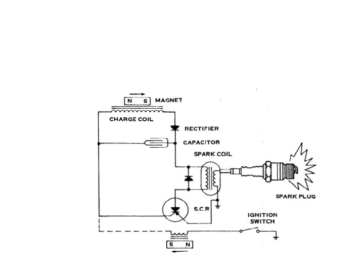
SOLID STATE IGNITION • Solid state is a broad term applied to any engine’s ignition system which uses electronic devices such as diodes, transistors, silicon controlled rectifiers or other semiconductors in place of one or more standard ignition components. • Electronic components are extremely small, have no moving parts, require nomechanical adjustments, are not subjected to wear, as with mechanical devices, deliver uniform performance throughout component life and under adverse operating conditions, and can be hermetically sealed, thus unaffected by dust, dirt, oil or moisture.
• Main difference between solid state and conventional ignition is the substitution of electronic components and circuitry for mechanical devices.
• As flywheel magnets pass solid state module laminations, a low voltage alternating current is induced into charge coil. • his alternating current passes through a recifier, transforming it into direct current. Current is then stored in capacitor.
• Flywheel magnets rotate approximately 355’ until they pass laminations, inducing a small electrical charge into trigger coil. At starting speeds, this charge has proper magnitude to turn on the silicon controlled rectifier (solid state switch) at retarded position for easy starting. • When engine reaches approximately 800 revolutions per minute, advance firing commences. Flywheel magnets travel approximately 335° at which time enough voltage is induced to trigger coil to fire the silicon controlled rectifier (solid state switch)
• When the silicon controlled rectifier is triggered, up to 300 volts stored in capacitor travel to spark coil where it is stepped up instantaneously to a maximum of 30, 000 volts and discharged across electrodes of spark plug.