Industrial training in ecil Hyderabad Presented by T
")
Industrial training in ecil, Hyderabad Presented by T. MADHUBABU (M 110448 EE)

Ecil Organization profile � 1. Control system group � 2. Computer maintenance group � 3. Communication systems group � 4. Components group � 5. Strategic Electronics group � 6. Instrument group

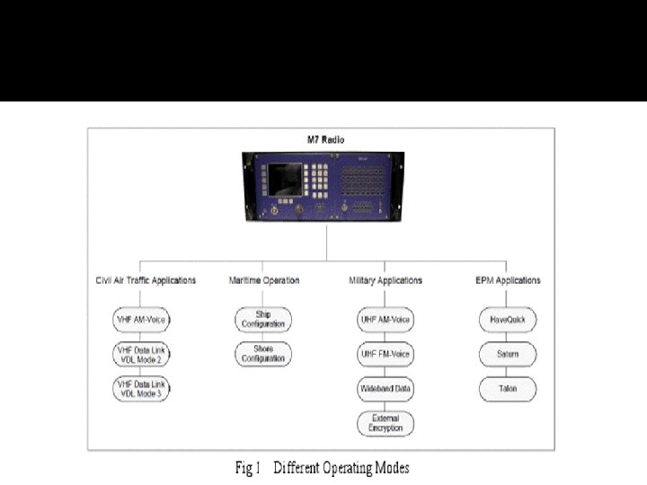
Digital V/UHF RADIO �M 7 VHF/UHF range of radios is designed for defense forces fulfilling a comprehensive range of demanding communication needs in the fixed, maritime, deployable applications. �High RF power: 50 W AM, 100 W FM �Multimode software defined radio �Electronic protection measures (EPM) �Continuous AM and FM coverage from 100 MHz 400 MHz �Integrated Power Supply

q M 7 is ideally suited for dual use operations �continuous AM and FM coverage from 100 to 400 MHz includes � 118 -137 MHz Commercial ATC � 137 -156 MHz Land Mobile band � 156 -163 MHz Maritime band � 225 -400 MHz Military band.
 –DIGITAL")
OPERATION Radio can be operated in Two modes: o EPM (electronic protection measure) –DIGITAL V/UHF XS o Non-EPM –DIGITAL V/UHF X Radio can be operated in following ways: �Locally using the front panel controls and indicators �Remotely using an DIGITAL V/UHF series controller �Remotely using compatible control equipment

Block diagram of v/uhf radio

specifications �Harmonics �Modulation �Sensitivity �Selectivity �Frequency response �Distortion �squelch

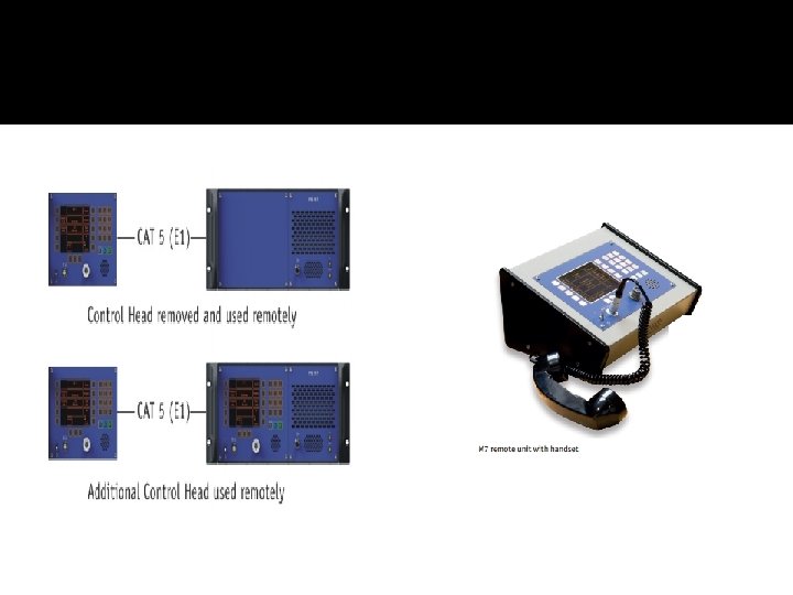
Remote control unit �The DIGITAL V/UHF C remote controller allows one or more DIGITAL V/UHF radios to be operated from a remote location �The Control Head can also be used separately as a Remote Controller �the desktop controller consists of an AC/DC power supply and an interface card.

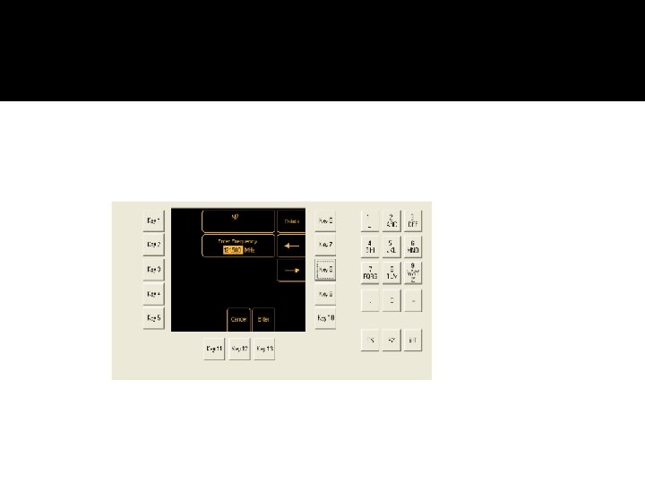
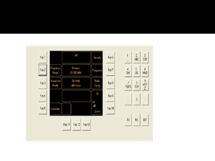
Tuning the Radio �Waveform Profiles �A waveform profile is a set of instructions stored in the radio that define a mode of operation and certain parameters associated with the mode. Up to 20 waveform profiles can be created and stored in the radio. �Frequency Preset There are three methods of tuning the radio o Tuning Using the Current Waveform Profile o Tuning by Recalling a Stored Frequency Preset

Tuning Using the Current Waveform Profile

Tuning by Recalling a Stored Waveform Profile

Tuning by Recalling a Stored Frequency Preset

E 1 RADIO INTERCONNECT

Features �E 1 -RIC provides a digital end-to-end connection between the radios and a digital VCCS using E 1 data. Digital Networks: v Consolidates digital audio, E&M and v RCMS for 29 channels onto a single E 1 bearer v Fault tolerant distributed architecture for safety critical applications

Analogue Networks: �Consolidates RCMS for 32 channels onto a single data port �Provides automatic main/standby 4 -wire E&M switching

General characteristics Radio compatibility E 1 RIC compatible with PAE and M 7 series radios Channel supported Each E 1 RIC supports 8 simplex channels , or 8 duplex channels Undedicated Inputs and Outputs 4 user configured inputs and outputs, monitored and controlled via RCMS (PAE MARC) are available. Operating temperature Storage temperature -20°C to +55°C -30°C to +70°C E 1 Characteristics 2. 048 M bits/s using a balanced 120 ohm electrical interface Response times Voice latency E and M signaling RCMS data 0. 25 ms 4 ms 50 ms

E 1 time slots

Functional Description �Voice and Signalling �Routing Conventions-Transmit Circuits �Routing Convocations - Receive Circuits �RCMS Data �Voice selection

MARC Functionality RCMS data available in two formats: �It is available in time slot T 31 of the E 1 data stream that connects the VCCS. Any RCMS information required by the VCCS is decoded whilst passing the data on to the MARC application. �It is available in RS 232 format on the facilities connector and the Auxiliary connector. (This is normally used in an analogue applications

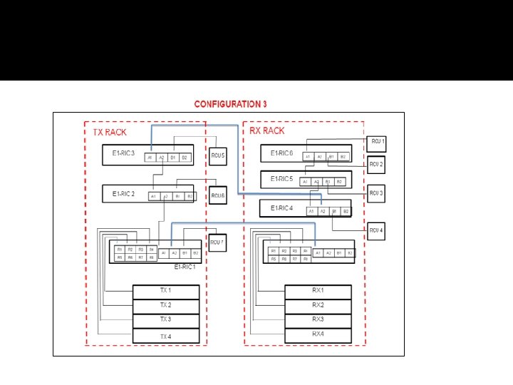
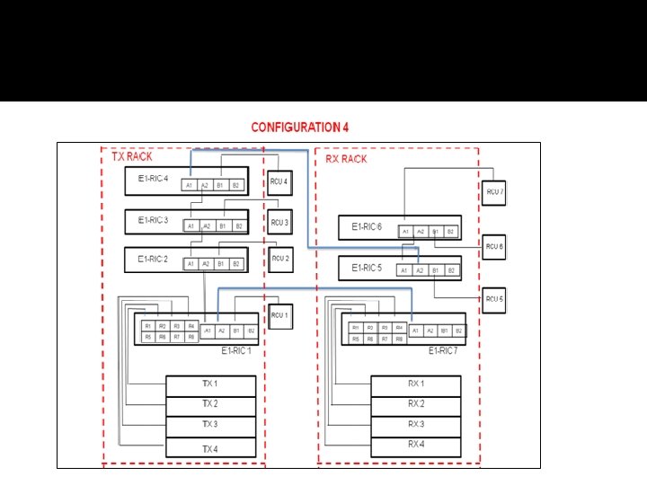
System configuration

Configuration 1

Configuration 2

Thank you
- Slides: 29