Induction Mutual Inductance current and emf induced in
 induced in a nearby circuit. •")

 • If current increases, V will drop")
 • If current remains constant, then (di/dt)")
 • Remember only a changing current will")
 – i. R =")
 – i. R =")
 – i. R =")
 – i. R =")
 – i. R =")
 – i. R =")
 – i. R =")
 is")

 = Io e -t(R/L)")
- Slides: 21
Induction • Mutual Inductance – current (and emf) induced in a nearby circuit. • Self Inductance – current induced in a circuit’s own wires • Induced current OPPOSES any change in current.
Induction • The purpose of an inductor is to oppose any change in current to maintain a steady current throughout the circuit.
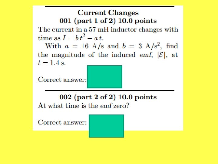
Induction • V = - L (di/dt) • If current increases, V will drop (as noted by the negative sign) • If current decreases, V will rise • Both affects are in opposition to the change in current
Induction • V = - L (di/dt) • If current remains constant, then (di/dt) = 0 and the voltage across the inductor = 0.
Induction • V = - L (di/dt) • Remember only a changing current will induce a changing magnetic field…and only a changing magnetic field can induce a separate current
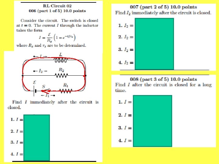
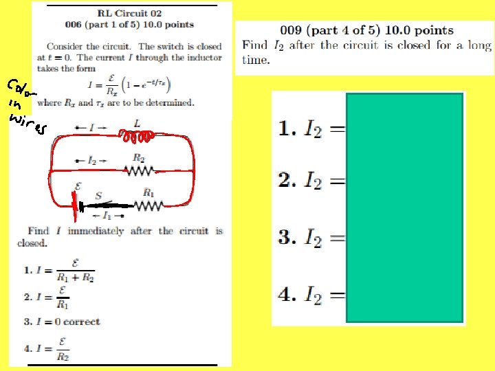
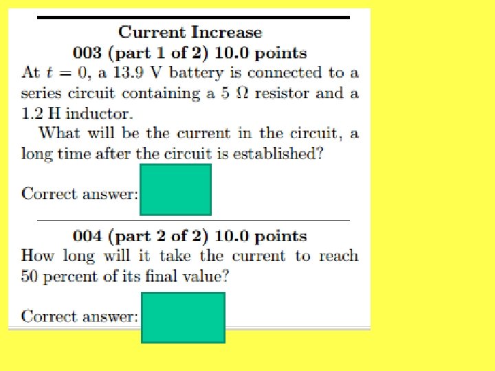
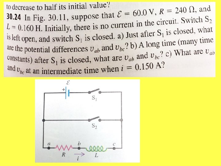
L R V By Kirchoff’s Loop Rule: +V – L(di/dt) – i. R = 0 • When circuit is initially closed, current will increase from zero, therefore the inductor will oppose that increased current.
L R V By Kirchoff’s Loop Rule: +V – L(di/dt) – i. R = 0 • Hence, current will not immediately get up to maximum amount (as it would if only a resistor was present).
L R V By Kirchoff’s Loop Rule: +V – L(di/dt) – i. R = 0 • See graph on pg. 1161 for current as a function of time.
L R By Kirchoff’s Loop Rule: V +V – L(di/dt) – i. R = 0 • Eventually, current will reach its steady state maximum value (as though there was only a resistor)
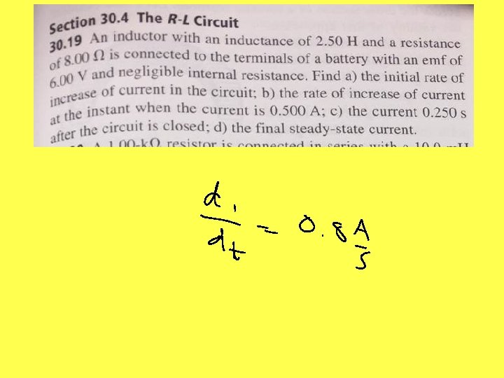
L R V By Kirchoff’s Loop Rule: +V – L(di/dt) – i. R = 0 • Initially: io = 0 so • V = L(di/dt) and (di/dt) =
L R V By Kirchoff’s Loop Rule: +V – L(di/dt) – i. R = Now the inductor is only a long conductor attached to the high voltage side of the battery. No Resistance so there should be no voltage 0 drop… • Finally at steady state (max I): (di/dt) = 0 so • V = i. R = If. R (Ohm’s Law)
L R V By Kirchoff’s Loop Rule: +V – L(di/dt) – i. R = Now the inductor is only a long conductor attached to the high voltage side of the battery. No Resistance so there should be no voltage 0 drop… • Finally at steady state (max I): (di/dt) = 0 so • V = i. R = If. R (Ohm’s Law)
L R V At all times in between initial and final current, i(t) is given by: i(t) = (1 – e -t(R/L))
L R V When the switch is open once again, the current changes, therefore the inductor will oppose the current loss. Hence, the current will not cut off immediately, but will gradually approach zero. (see pg. 1163 for a graph of this relation).
L R V During this process, i(t) = Io e -t(R/L)