Induction Motor Vector Control Group F Group Members

Induction Motor Vector Control Group F
 • Control System (Design) • Control")
Group Members and Responsibilities • Justin Barwick (EE) • Control System (Design) • Control System Implementation (Secondary) • Chris Guido (Cp. E) • Control System Implementation • User Interface • Merritt Robbins (EE) • Power System (High Voltage) • Will Santos (EE) • Power System (Low Voltage)

Motivation • Electric motors are an already enormous, ever - expanding industry • ~45% of the world’s electricity (Waide, 2011) [1] • AC induction motors offer performance benefits vs DC motors • Efficiency • Reliability • Simplicity • Electric transportation systems • Tesla Motors • Variable - speed industrial applications • Machine tools • HVAC
 • Design high voltage power")
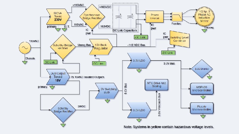
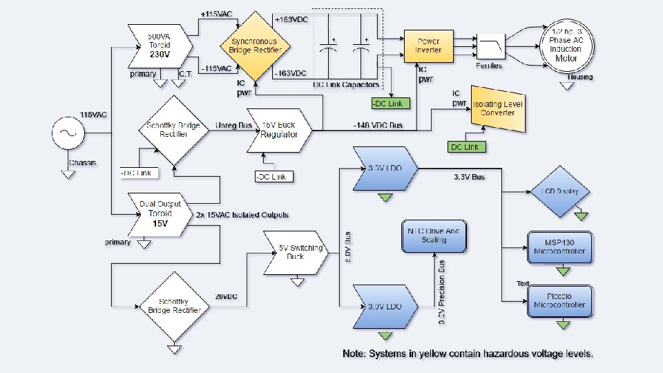
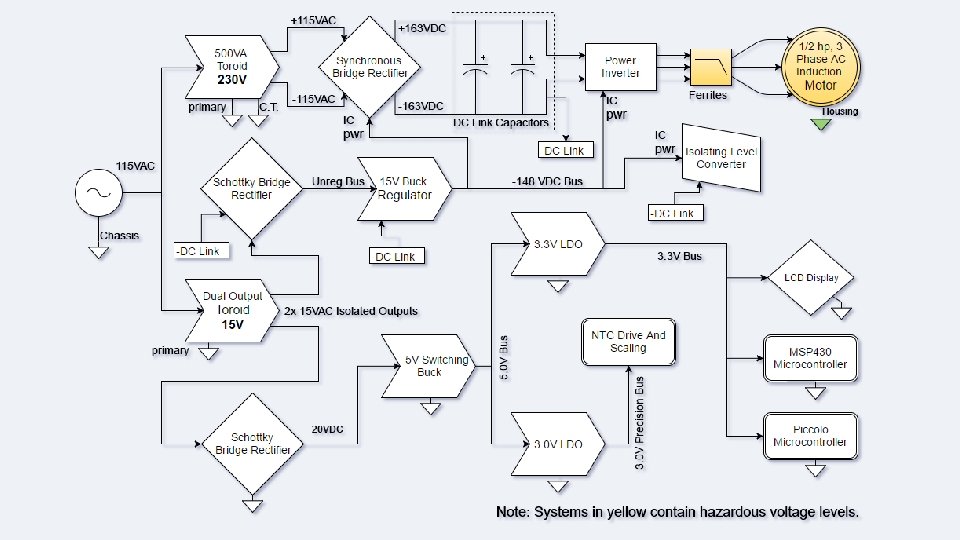
Goals and Objectives • Implement Field Oriented Control (FOC) • Design high voltage power system (325 V DC bus) • Low voltage DC bus regulation • 15 V, 8. 5, 4 V, 3. 6 V, 3. 3 V • Implement two embedded processors • Divide computation to improve performance • High voltage Isolated Measurements • Phase voltage, current • Temperature
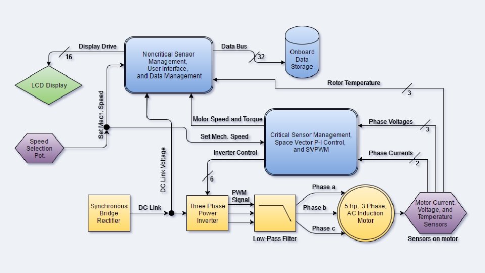

Controlling the Motor Utilizing Space Vector Pulse-width Modulation

Overview • V/Hz Conversion • Clarke and Park Transformation • Inverter State Projections • PWM Generation

Generating the Reference Signal • Speed to Frequency Conversion • Volts over Hertz Conversion

Speed to Frequency Conversion • Determine number of poles • Receive voltage from potentiometer • Convert voltage to speed and speed to frequency

Volts over Hertz Conversion V/Hz Conversion 250 • Determine operating boundaries • Maintain constant flux Voltage (V) 200 150 100 50 0 0 5 10 15 20 25 30 35 40 45 50 55 60 65 Frequency (Hz)

Performing Transformations • Clarke Transformation • Park Transformation

Clarke Transformation • Geometric relationship • Two pair-pole windings • Power invariance • Benefits: • Independent variable reduction • Intermediate step

Clarke Transformation C • Geometric relationship • Two pair-pole windings B • Power invariance A • Benefits: • Independent variable reduction • Intermediate step

Clarke Transformation C 45⁰ • Geometric relationship C’ • Two pair-pole windings B 45⁰ • Power invariance A A’ B’ • Benefits: • Independent variable reduction • Intermediate step

Clarke Transformation C • Geometric relationship • Two pair-pole windings 0 B • Power invariance ≈ 35. 3⁰ A α β • Benefits: • Independent variable reduction • Intermediate step

Clarke Transformation β • Geometric relationship Ns Nαβ B • Two pair-pole windings Ns 120⁰ Nαβ A, α • Power invariance Ns C • Benefits: • Variable reduction • Intermediate step

Park Transformation • Geometric relationship • Rotating reference frame • Benefits: • Variable simplification • Independent control of torque and flux

Park Transformation β Ns • Geometric relationship Nαβ B θ • Rotating reference frame θ Ns 120⁰ • Benefits: Ns • Variable simplification • Independent control of torque and flux C Nαβ A, α

Park Transformation q Ns • Geometric relationship ω = synchronous speed δ = slip of rotor Nαβ B ωt+δ • Rotating reference frame ωt+δ Ns 120⁰ • Benefits: Ns • Variable simplification • Independent control of torque and flux C Nαβ A, d

Space Vector Pulse-width Modulation • Space Vector Mapping • Inverter State Projections • PWM Generation

Space Vector Mapping • Phase and polarity assignment • Minimize inverter switching

Space Vector Mapping Inverter State C phase B phase A phase V 0 0 V 1 0 0 1 V 2 0 1 0 V 3 0 1 1 V 4 1 0 0 V 5 1 0 1 V 6 1 1 0 V 7 1 1 1 • Phase and polarity assignment • Minimize inverter switching
 B, V 2 (010) • Phase and polarity")
Space Vector Mapping V 3 (011) B, V 2 (010) • Phase and polarity assignment 60⁰ A, V 1 (001) V 6 (110) • Minimize inverter switching C, V 4 (100) V 5 (101)
 B, V 2 (010) tm. Vs t 3")
Inverter State Projections V 3 (011) B, V 2 (010) tm. Vs t 3 V 3 60⁰ V 6 (110) A, V 1 (001) t 1 V 1 C, V 4 (100) V 5 (101)

Pulse-width Modulated Signal Generation • Utilize bit assignment • Utilize zero-sequence components

Control for Demo • PI complications • Determining the integral and proportional gains • Park Transform complications • Frequency and phase detection • Phase locking the sampled and reference signal

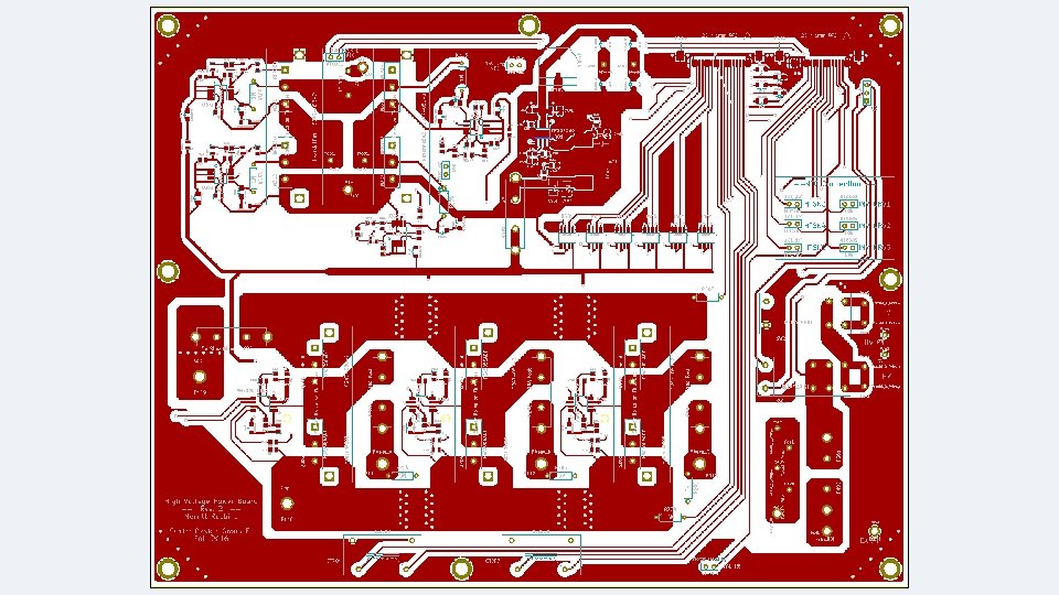
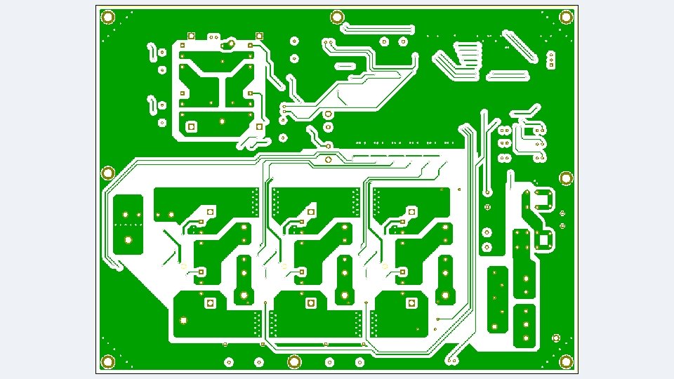
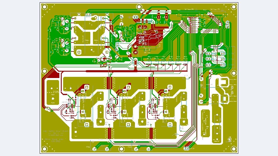
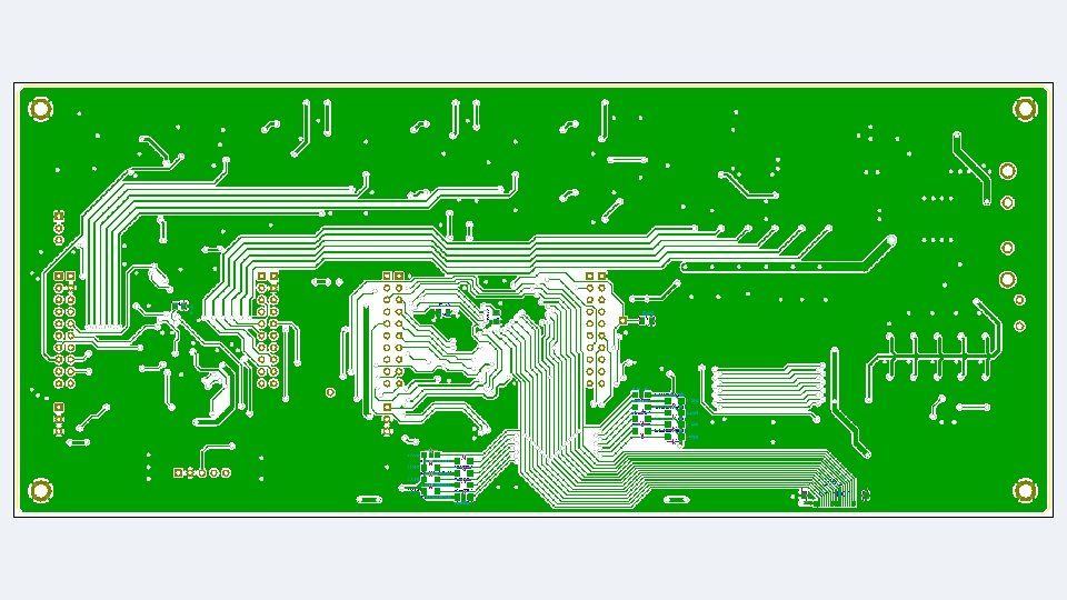
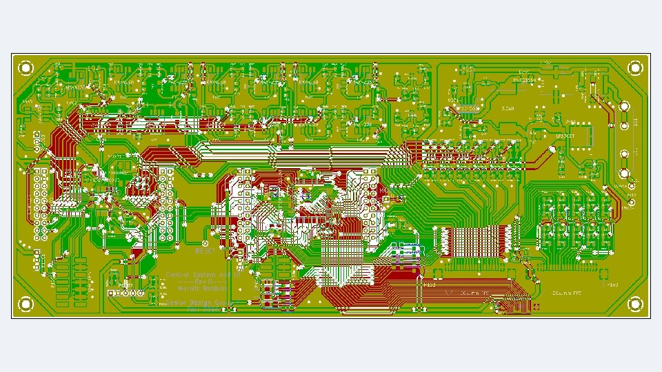
Design Approach • Mathematical Modeling • Numerical Calculation • Schematic Capture • Ki. Cad EDA suite • Power System • Separate high voltage from control system on different boards • High efficiency focus

General Design Decisions • Motor Selection • Reliance Electric ½ HP, 230 V/460 V fan cooled • Power Output Specification • 1/2 hp = 373 W

Synchronous Rectifier Gate Driver Part Number IR 1167 Manufacturer International Rectifier Input Voltage 12 ~20 V T_on / T_off 40 ns / 60 ns Maximum Drain Sense Voltage 200 V Package 8 - SOIC (Standard) Cost $2. 70 (1 qty) • Emulated ideal diode with a MOSFET • Senses V_DS and drives gate accordingly • Easy package to work with • Trimmable turn off threshold
 Part Number TK 62 N 60 X Manufacturer Vishay /")
Synchronous Rectifier Switches (MOSFET) Part Number TK 62 N 60 X Manufacturer Vishay / SIliconix Rated V_DS 400 V Rated I_D 10 A R_DS (ON) 300 m. Ohm Package TO-247 Cost $2. 70 (1 qty) • • Low cost for 400 V rating 0. 3 Ohms * 0. 4 A 2 = 0. 048 W Common package 10 V gate charge
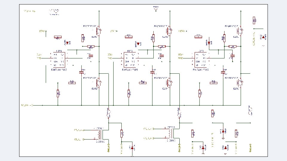

Power Inverter Gate Driver Part Number FAN 7190 M_F 085 Manufacturer Fairchild High Side Voltage 650 V Minimum Pulse Width 80 ns Package 8 - SOIC (Standard) Cost $1. 62 (1 qty) • Standard package • High and low side in one chip • Capable of driving around 0. 299. 8% duty cycle at 20 k. Hz switching frequency
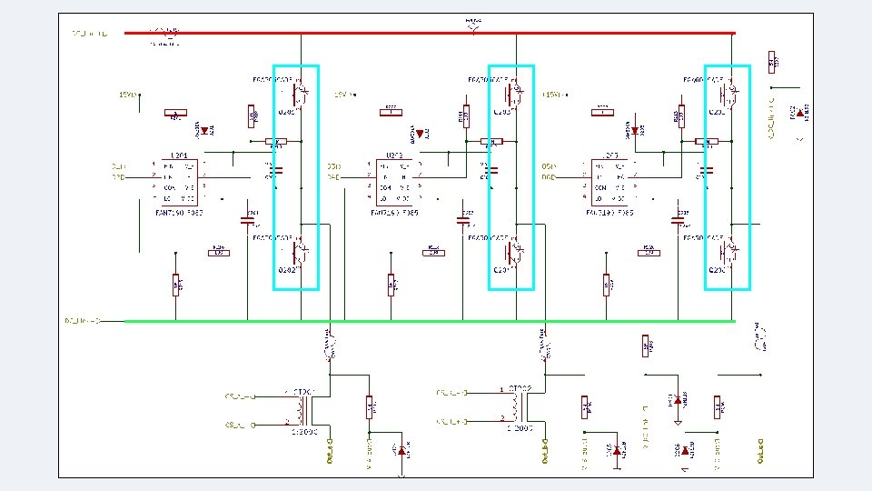
 Part Number FGA 5065 ADF Manufacturer Fairchild Ratec V_C 650")
Power Inverter Switch (IGBT) Part Number FGA 5065 ADF Manufacturer Fairchild Ratec V_C 650 V Cont. I_C 50 A (100 A pulses) Package TO - 3 PN Cost $4. 79 (1 qty) • Small package • Extremely high current rating • Low losses

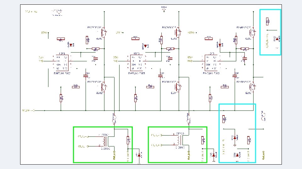
Synchronous Rectifier Gate Driver Part Number CR 8348 -2000 -F Manufacturer CR Magnetics Inc. Frequency Range 20 Hz ~ 200 k. Hz Current Rating 50 A Turns Ratio 1: 2000 Package 24 x 11 mm Thru-Hole Cost $7. 05 (1 qty) • High turns ratio for low power sensing • Selfisolates • Eliminating the need for isolation amplifiers • Decently sized packages • Perfect frequency range for application

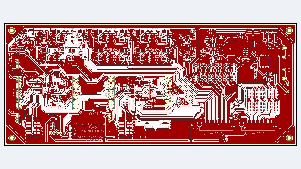
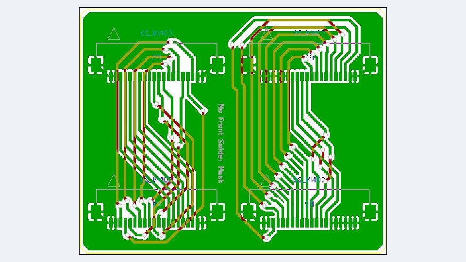
Adapter Board • Flat flex connectors were partially mirrored • Designed an adapter board • Delivery scheduled 11/28/16 • Arrived this morning

Rotary Encoder Part Number AEAT-601 B Manufacturer Broadcom / Avago Cycles per Revolution 256 Channels 3 (A, B, I) Package Shaft Mounted (5 mm) • Three channels indicating position, direction, and complete revolution • Tolerant of high temperatures (125°C)

Low Voltage Power System By William Santos

Low Voltage Regulation Regulator Design Considerations • Efficiency/Power Dissipation • Application (Switching or Linear Regulation) Switching Regulator Selection • Texas Instruments TPS 54560 • Linear Technology LTC 3649 Linear Voltage Regulation • Linear Technology LT 3008 • Texas Instruments TPS 73130

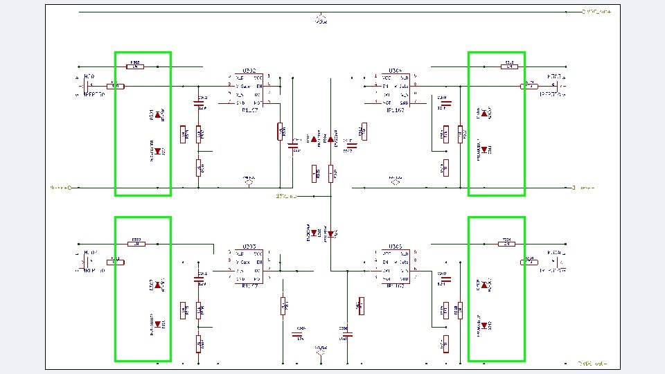
Full Wave Schottky Bridge Rectifier Purpose • Provides the main DC bus for the Low Voltage Electronics Design Considerations • Diode Type (Schottky) • Low Vf • Good Conduction Characteristics • Smoothing Capacitance NXP PMEG 3050 Manufacturer Average Forward 5 A Current Forward Voltage 300 m. V Package SOD-123

Switching Regulator IC Considerations • Losses • Switching loss, gate drive loss, and supply current losses are negligible • Conduction loss provides the largest contribution to total power dissipation • Power and Efficiency Characterization Switching Regulator Max Power Dissipation Efficiency TPS 54560 1. 02 W 85%-90% LTC 3649 1. 82 W 85%-90%

TPS 54560 • Purpose • Provides the 15 V rails referenced to the DC_Link- for the inverter • Provides 4 V LV DC rail for other regulator loads • Selection Criteria • Low Power Dissipation • High Efficiency at normal loads • PCB Layout Considerations • Frequency Dependent Elements • Catch Diode/Inductor • Need to be close to SW pin Manufacturer Texas Instruments Part Number TPS 54560 Power Required 20 V Switching Frequency 100 k. Hz-2 MHz Output Current (Max) 5 A Package HSOP(8) Efficiency 85%-90% Price $5. 65

15 V Output Switch Mode Power Supply

Switching Regulator Catch Diode Selection • Purpose • Reverse Polarity Protection • Selection Criteria • Peak Reverse Voltage • Conduction Loss Minimal (1. 5 W at worst) • Low Vf • Low Reverse Power Dissipation Manufacturer NXP Part Number PMEG 4030 ER Peak Reverse Voltage 40 V Peak Output Current 3 A Package SOD-123 Price $0. 41

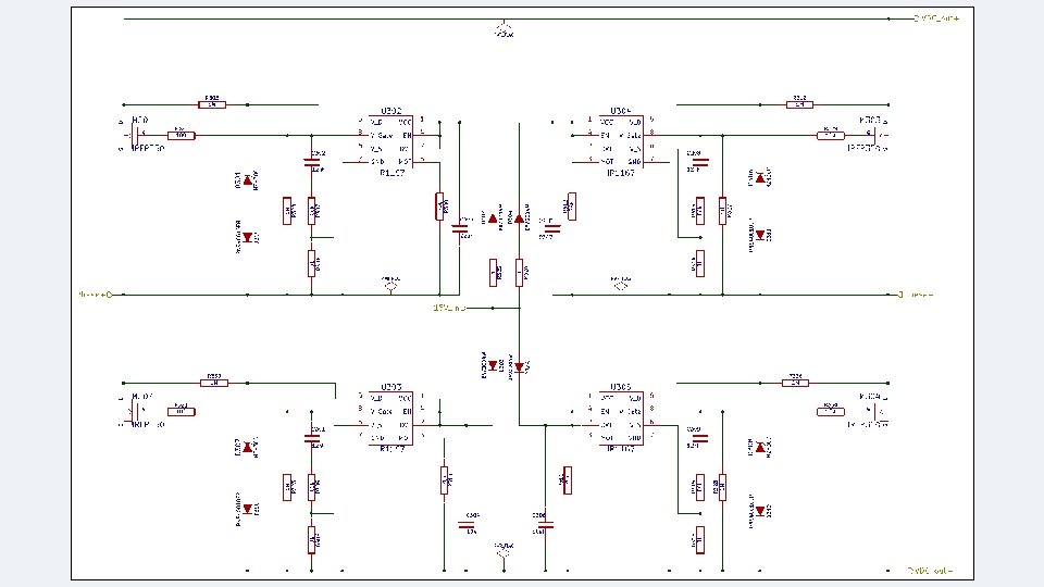
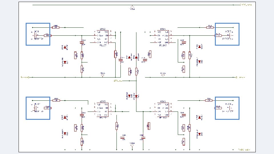
LDO Linear Regulators Purpose • Provide supply voltages to the MCUs and Thermistor Sensors Initial Selection • LT 3008 was chosen for post regulation to MCUs • Output Current of 20 m. A is much too small Final Selection • TPS 73130 (150 m. A) • LF 33 C (500 m. A)

TPS 73130 Purpose • Provides supply voltage to the Thermistor Networks Advantages • Simple Implementation • Provides the appropriate output current • Voltage Regulation Accuracy (1%)

LF 33 AB Purpose • Provides the supply voltage to the MCUs Justification • TMS Piccolo Sources max 100 m. A • MSP 430 Sources ~150 u. A

Issues • Determination of Induction Motor Parameters • Performance of No Load and Blocked Rotor Test • Need additional Resources • Construction of encoder interface • LCD screen

Budget and Financing • Carey Family Donation - $500. 00 • Self financed

Implementation Utilizing the Piccolo Controller

TMS 320 F 28027 F Launchpad • Selection Criteria • High clock speed • Enhanced control peripherals • 4 e. PWM channels • 7 ADC channels with 13 -bit resolution

Software Tools • control. SUITE™ • Set of software infrastructure and tools • Provides datasheets, libraries, and other resources for specific devices

Control Algorithm Implementation Initialization PWM Signal Generation If reference signal period not reached End of reference signal, or motor not spinning Re-evaluate Reference Frequency

Initialization • Configure Peripherals for Operation • CPU Timer • ADC Channels • Sample Window Size • Conversion Triggers • PWM Channels • Clock Speed • Time-Based Period Initialization PWM Signal Generation Re-evaluate Reference Frequency

Initialization • Initialize Frequency for Reference Signal and Desired Frequency • Sample ADC • Initialize Flags • Direction Flag • Indicates that motor has changed direction • Change Flag • Tells system that user wants motor to change direction • Is set when user presses button Initialization PWM Signal Generation Re-evaluate Reference Frequency

PWM Generation Initialization PWM Signal Generation If reference signal period not reached End of reference signal, or motor not spinning Re-evaluate Reference Frequency

PWM Generation Check Toggle Button Check Counter and Motor Speed Create Reference Signal Send PWM Signal Clarke Transformation SVPWM Calculation

PWM Generation • Indicates user wants the motor to spin in opposite direction Check Toggle Button Check Counter and Motor Speed Create Reference Signal Send PWM Signal Clarke Transformation SVPWM Calculation

PWM Generation • Generate three signals based on current motor status and desired motor status • Each signal is 120° out of phase of the others • Amplitude is determined by V/Hz calculation Check Toggle Button Check Counter and Motor Speed Create Reference Signal Send PWM Signal Clarke Transformation SVPWM Calculation

PWM Generation • Perform Clarke Transformation • Determines equivalent α and β values in rotated reference frame Check Toggle Button Check Counter and Motor Speed Create Reference Signal Send PWM Signal Clarke Transformation SVPWM Calculation

PWM Generation • Projects α and β values onto Inverter-State vector map • Utilizes individual inverter states and time durations • Generates PWM duty-cycle as a ratio of the Time-Based Period register value Check Toggle Button Check Counter and Motor Speed Create Reference Signal Send PWM Signal Clarke Transformation SVPWM Calculation

PWM Generation • Sets compare values for each PWM channel to switch inverter states as necessary Check Toggle Button Check Counter and Motor Speed Create Reference Signal Send PWM Signal Clarke Transformation SVPWM Calculation

PWM Generation • Determines end of period of reference signal • Also determines if motor is no longer spinning Check Toggle Button Check Counter and Motor Speed Create Reference Signal Send PWM Signal Clarke Transformation • This indicates the motor is most likely changing direction • If either condition is met, revaluate reference frequency. • Otherwise repeat process SVPWM Calculation

Re-evaluate Reference Frequency Initialization PWM Signal Generation If reference signal period not reached End of reference signal, or motor not spinning Re-evaluate Reference Frequency

Re-evaluate Reference Frequency Reached End of Period Check Change Flag Is Set Sample ADC for Desired Frequency Motor is Not Spinning Check Change Flag Switch PWM Channels for B and C Phase Voltages Flag Is Not Set Compare Desired Frequency with Motor Speed Decrement Reference Signal Frequency Set Direction Flag Increment or Decrement Reference Signal Frequency Accordingly Reset Change and Direction Flag if at Desired Speed Reinitialize Counter Increment Reference Signal Frequency Reinitialize Reference Signal Frequency Reinitialize Counter
 • Compares current reference signal frequency with")
Re-evaluate Reference Frequency (Reached End of Period) • Compares current reference signal frequency with desired frequency set by user • Ramps reference signal frequency up or down accordingly • Loops back to generating PWM Check Change Flag Is Set Sample ADC for Desired Frequency Compare Desired Frequency with Motor Speed Decrement Reference Signal Frequency Increment or Decrement Reference Signal Frequency Accordingly Reset Change and Direction Flag if at Desired Speed Reinitialize Counter
 • If Change Flag is set, motor")
Re-evaluate Reference Frequency (Reached End of Period) • If Change Flag is set, motor is changing directions • Decreases reference signal frequency until motor is no longer spinning Check Change Flag Is Set Sample ADC for Desired Frequency Compare Desired Frequency with Motor Speed Decrement Reference Signal Frequency Increment or Decrement Reference Signal Frequency Accordingly Reset Change and Direction Flag if at Desired Speed Reinitialize Counter
 • Motor is not spinning and is")
Re-evaluate Reference Frequency (Motor is Not Spinning) • Motor is not spinning and is not changing direction • This condition should only be met when the system is starting up Check Change Flag Switch PWM Channels for B and C Phase Voltages Set Direction Flag Reinitialize Reference Signal Frequency Reinitialize Counter Flag Is Not Set Increment Reference Signal Frequency
 • Motor is not spinning and is")
Re-evaluate Reference Frequency (Motor is Not Spinning) • Motor is not spinning and is changing direction • Switch PWM channels to reverse direction of motor • Loops back to generating PWM Check Change Flag Switch PWM Channels for B and C Phase Voltages Set Direction Flag Reinitialize Reference Signal Frequency Reinitialize Counter Flag Is Not Set Increment Reference Signal Frequency

Issues • Feedback System • Park Transformation • PI Controller • User Feedback • MSP 430 Implementation • SPI Communication • LCD Display
![Works Cited [1] Waide, Paul, Brunner, Conrad U. , et al. : Energy-Efficiency Policy](http://slidetodoc.com/presentation_image/5611172d803d1adab2120cb5840aecdc/image-87.jpg "Works Cited [1] Waide, Paul, Brunner, Conrad U. , et al. : Energy-Efficiency Policy")
Works Cited [1] Waide, Paul, Brunner, Conrad U. , et al. : Energy-Efficiency Policy Opportunities for Electric Motor-Driven Systems. International Energy Agency Working Paper, Energy Efficiency Series, Paris 2011
- Slides: 87