Induction Motor Asynchronous Motor The threephase induction motors
 The three-phase induction motors are the most widely used electric")
 It has simple and rugged construction. (ii) It is relatively cheap. (Low")
 Stationary part")


 (5) and (6) in equation (1) T α E 2 I 2")
 Rotor current I 2 is defined as the ratio of")
 (5) and (6) in equation (1) T α E 2 I 2")
 Rotor current I 2 is defined as the ratio of")


- Slides: 40
Induction Motor (Asynchronous Motor) The three-phase induction motors are the most widely used electric motors in industry (small workshops to large industries) These motors are employed in applications such as centrifugal pumps conveyers compressors crushers drilling machines etc.
Advantages (i) It has simple and rugged construction. (ii) It is relatively cheap. (Low Cost) (iii) It requires little maintenance. (iv) It has high efficiency (v) Reasonably good power factor. (vi) It has self starting torque. (vii) absence of commutator Disadvantages (i) Its speed is not constant, when load is varied. (ii) Low starting torque compared to DC shunt motor.
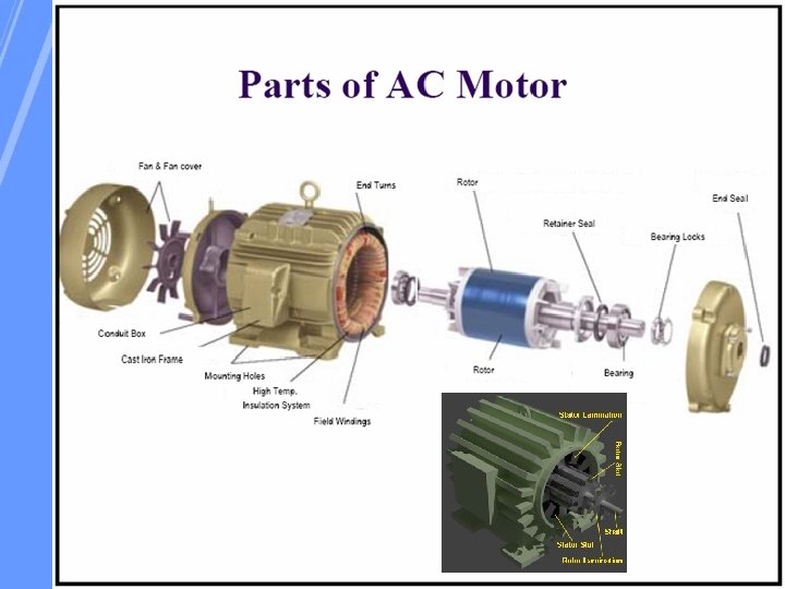
Constructional details A 3 -phase induction motor comprises two electromagnetic parts: (i) Stationary part called the Stator (ii) Rotating part called the Rotor The stator and the rotor are each made up of Ø An electric circuit, usually made of insulated copper or aluminium winding, to carry current. Ø A magnetic circuit, usually made from laminated silicon steel, to carry magnetic flux
Stator The stator of the three phase induction motor consists of three main parts: 1. Stator frame 2. Stator core 3. Stator winding or field winding
0. 4 to 0. 5 mm thick
The stator is the outer stationary part of the motor, which consists of • The outer cylindrical frame of the motor or yoke, which is made either of welded sheet steel, cast iron or cast aluminium alloy. • The magnetic path, which comprises a set of slotted steel laminations called stator core pressed into the cylindrical space inside the outer frame. The magnetic path is laminated to reduce eddy currents, reducing losses and heating. • A set of insulated electrical windings, which are placed inside the slots of the laminated stator. For a 3 -phase motor, 3 sets of windings are required, one for each phase connected in either star or delta
Rotor • The rotor is the rotating part of the electromagnetic circuit. • It can be found in two types: – Squirrel cage – Wound rotor • However, the most common type of rotor is the “squirrel cage” rotor.
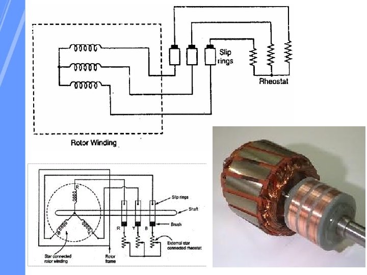
v Squirrel cage type: ØRotor winding is composed of copper bars embedded in the rotor slots and shorted at both end by end rings ØSimple, low cost, robust, low maintenance v Wound rotor type: ØRotor winding is wound by wires. The winding terminals can be connected to external circuits through slip rings and brushes. ØEasy to control speed, more expensive.
Short circuits all rotor bars. /rotor winding
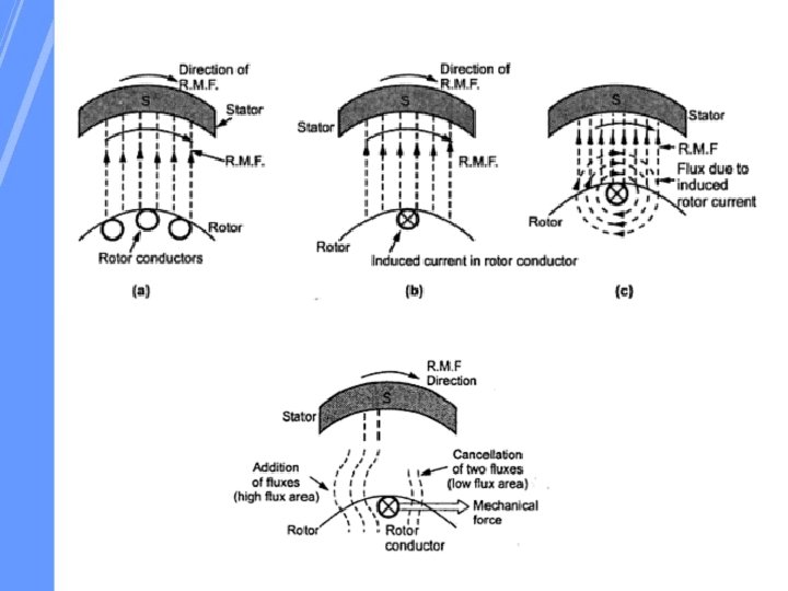
Principle of operation of three phase Induction Motor
Rotating Magnetic Field
Rotating Magnetic Field
Slip on Induction motor
1. Rotor Frequency fr = sf 2. Magnitude of Rotor induced EMF E 2 r = s. E 2 3. Rotor Resistance and reactance X 2 r = s. X 2
Torque Equation The torque produced in induction motor depends o the following factors 1. The part of RMF which reacts with rotor 2. Rotor Current in running conditions 3. Power factor of the rotor in running conditions T α Ф I 2 r Cos Ф 2 r (1) Where, T Ф I 2 r Cos Ф 2 is the torque produced by induction motor, is flux responsible of producing induced EMF is rotor current in running condition, is the power factor of rotor circuit in running condition The flux Ф produced by the stator is proportional to stator E 1. (Stator Voltage) Ф ∝ E 1 (2)
We know that transformation ratio “K” is defined as the ratio of secondary voltage (rotor voltage) to that of primary voltage (stator voltage) (3) From (2) and (3) Ф ∝ E 1 Ф ∝ E 2 (4) Thus equation (1) can be replaced by E 2 T α E 2 I 2 r Cos Ф 2 r We Know (5) (6)
Substitute (4) (5) and (6) in equation (1) T α E 2 I 2 r Cos Ф 2 r (7) K constant (8) (9)
Starting Torque S=1 (10) Rotor current I 2 is defined as the ratio of rotor induced emf under running condition , s. E 2 to total impedance, Z 2 of rotor side,
Substitute (4) (5) and (6) in equation (1) T α E 2 I 2 r Cos Ф 2 r T α E 2 x x (7) K constant (8) (9)
Starting Torque S=1 (10) Rotor current I 2 is defined as the ratio of rotor induced emf under running condition , s. E 2 to total impedance, Z 2 of rotor side,
CONDITIONS FOR MAXIMUM TORQUE From the torque equation, the torque depends on the SLIP at which motor is running V SLIP T E 1 E 2 constant is variable and controlling parameter Maximum Torque Differentiate T with respect to S (U/V) method
This is the slip at which torque is max.
Torque SLIP Characteristics Supply voltage is constant E 2 Now to Judge the nature of Torque Slip S=0 S=1 Low Slip Region R 2 is constant Tαs
High Slip Region
Torque Slip Characteristics
From NO LOAD to full load its speed decreases SLIP Increases
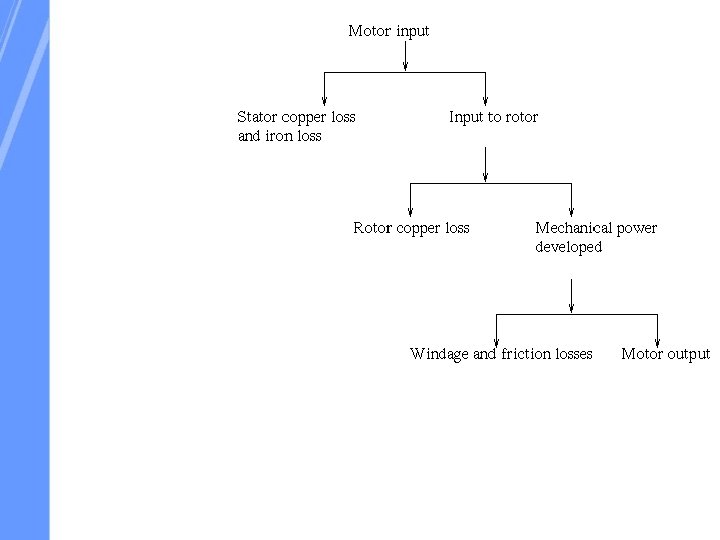
Losses and Efficiency of Induction Motor There are two types of losses occur in three phase induction motor. These losses are, 1. Constant or fixed losses, 2. Variable losses. 1. Iron or core losses, 2. Mechanical losses, 3. Brush friction losses.
Circle Diagram of an induction Motor No Load Test or Open Circuit Test Sl. no NO Load Voltage Rated Line Voltage Vo Volts No Load Current Io Amps No Load Input Power Wo Watts
Blocked or Locked Rotor Test or Short Circuit Test Sl. no Short Circuit Voltage Vsc Volts Short Circuit Current Isc Amps Short Circuit Input Power Wsc Watts
From OC TEST Wo = √ 3 Vo Io cosΦo From SC TEST Wsc = √ 3 Vsc Isc cosΦsc Short Circuit Current at Normal Voltage AG = WSN Torque Line WSN = Short Circuit Power at Normal Voltage
Y V A ISN u p t u t Rotor Copper loss ne i L O E ne Li e u rq Stator Copper loss To Φsc Φo O F Io O’ C Fixed loss G D X
A’ Y Full load output V A ISN P u p t u t Rotor Copper loss ne i L O E ne Li e u rq Stator Copper loss To Φsc Φo O Q Io O’ R S F C Fixed loss G D X
A’ Y Full load output V J A ISN P Ou t u p t Rotor Copper loss ine L E Torq Φsc Φo O Io O’ Q R S T K ne i L ue Stator Copper loss F C Fixed loss G D X
Method to find Location E Stator Copper loss = 3 I 12 R 1 Rotor Copper loss = Wsc - 3 I 12 R 1
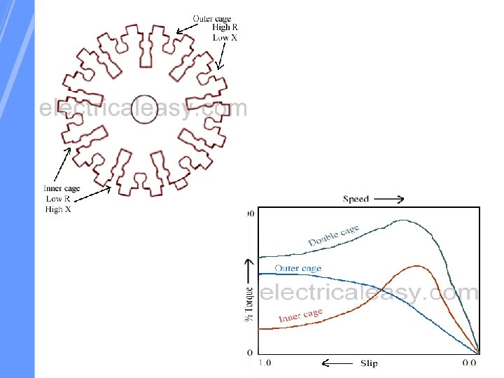
Double Cage Induction Motor Squirrel Cage Induction Motor has good running characteristics but starting torque is poor Slip ring Induction Motor has good running characteristics and good starting torque but Unsuitable for many types of application