In IEC 61000 2 5 1995 the IEC


: occurred at utility sub-transmission and distribution systems, capacitor bank energization: result")
 deviations at power frequencies for longer")


: Sag are usually associated with system faults but can also be caused by")


 in a three-phase system is defined as the ratio")


- Slides: 24
In IEC 61000 -2 -5: 1995, the IEC classifies electromagnetic phenomena into several groups as shown in Table 1. The IEC standard addresses the conducted electrical parameters shown in Table 1. The terms high frequency and low frequency are not defined in terms of a specific frequency range, but instead are intended to indicate the relative difference in principal frequency content of the phenomena listed in these categories.
IEEE Std 1159 -2009
Transient An event that is undesirable but momentary in nature Part of the change in a variable that disappears during transition from one steady state operation condition to another Surge It can be classified into two categories: Impulsive, oscillatory
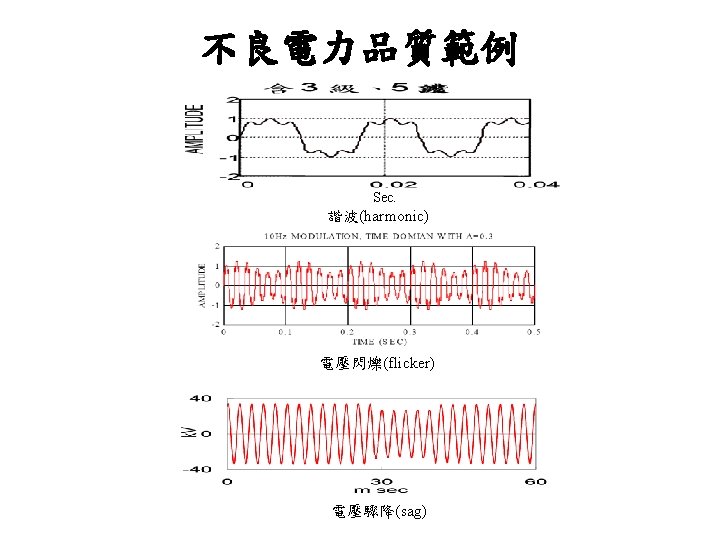
Impulsive transient 1. An impulsive transient is a sudden, non-power frequency change in the steady state condition of voltage, current or both, that is unidirectional in polarity 2. They are characterized by rise and decay times. 3. lightning 4. They are generally not conducted far from the occurred source 5. It can be divided into three parts Rise from zero to its peak value of 2000 V in 1. 2 , then decay to half its peak value in 50
Oscillatory transient 1. An oscillatory transient is a sudden, non-power frequency change in the steady state condition of voltage, current or both, that includes both positive and negative polarity values 2. They are characterized by spectral content, duration and magnitude. 3. It can be divided into high, medium and low frequency three parts HF(>500 k. Hz, 5 us, 0 -4 pu): the result of a local system responses to an impulsive transient MF(5 -500 k. Hz, 20 us, 0 -8 pu): fig. 2 -2, cable switching or impulsive transient
LF(<5 k. Hz): occurred at utility sub-transmission and distribution systems, capacitor bank energization: result is oscillatory voltage transient with frequency 300 -900 Hz. Peak magnitude can reach 2. 0 pu(typically 1. 3 -1. 5), duration 0. 5 -3 cycles
Long-Duration Voltage Variations 1. Long-duration variations encompass root-mean-square(rms) deviations at power frequencies for longer than 1 min 2. 3. 4. Over-voltage: rms voltage greater than 1. 1 pu, duration longer than 1 min switching off a large load, energizing a capacitor bank, weak system, inadequate voltage control(TX OLTC, Gen AVR. . ) 3. Under-voltage: rms voltage less than 0. 9 pu, duration longer than 1 min 4. Sustained Interruption: rms voltage drop to zero, duration longer than 1 min(outage: it is the same as interruption for utility. For user, any interruption of power that shuts down a process. This could be as little as one-half of a cycle. )
Short-Duration Voltage Variations Short-duration voltage variations are caused by fault conditions, the energization of large loads which require high starting current, or intermittent loose connects in power wiring.
Interruption: Interruption can be the result of power system faults, equipment failure, and control malfunctions. The duration of an interruption due to a fault is determined by the operating time of the protective devices
Sag(Dip): Sag are usually associated with system faults but can also be caused by energization of heavy loads or starting of large motors a 20 percent sag will be considered an event during which the rms voltage decreased by 20 percent to 0. 8 pu
Voltage sag caused by the starting of large motor stating
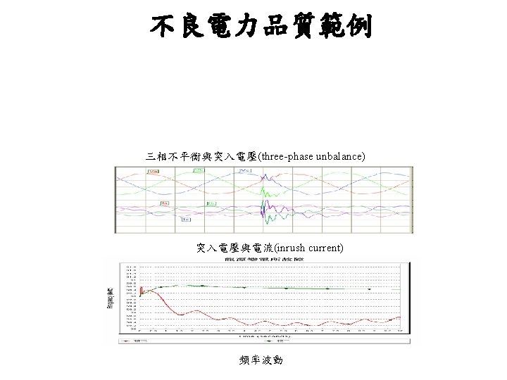
Swell: Unfaulted phases during a SLG fault, switching off a large load, or energizing a large capacitor bank. Swell are characterized by their rms magnitude and duration Ungrounded system: unfaulted phases will be 1. 73 pu during a SLG Grounded system: there will be little or no voltage rise on unfaulted phases Faults at different points along four-wire, multigrounded feeders will have varying of voltage swell as shown in the figure
Voltage Imbalance (sometimes called unbalance) in a three-phase system is defined as the ratio of the magnitude of the negative sequence component to the magnitude of the positive sequence component, expressed as a percentage. This definition can be applied for either voltage or current. Typically, the voltage imbalance of a three-phase service is less than 3%. The current imbalance can be considerably higher, especially when single-phase loads are present. Measuring instruments often use a definition of voltage imbalance based on ANSI C 84. 12006, which defines imbalance as the ratio of the maximum deviation of a voltage from the average voltage to the average voltage, expressed in percent, using phase-to-phase voltage measurements
This figure shows an example of a one-day trend of imbalance measured at one point on a residential feeder. The trace labeled “V Neg-Seq Imb Total” is using the preferred definition of imbalance. The trace of “V Zero-Seq Imb Total” is the ratio of the zerosequence-to-positive-sequence voltage. This is sometimes helpful to understand sources of asymmetry in the power system, particularly due to single phase loads connected phase to neutral. The trace labeled “V Imb Avg LN” is using the ANSI-type maximum deviation from the average definition, but on line-to-neutral quantities.
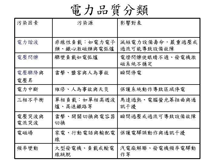
Waveform Distortion 1. Dc offset can occur as the result of a geomagnetic disturbance, the effect of half wave rectification. It will result in the saturation of transformer in normal operation 2. Harmonics and inter-harmonics 3. Notching 4. Noises are unwanted electrical signals with broadband spectral lower than 200 k. Hz. It can be caused by power electronic devices, control circuits, arcing equipment, rectifiers and SPS. Noise will disturb electronic devices such as microcomputer and programmable controllers.
Harmonic
Notching is a periodic voltage disturbance caused by the normal operation of power electronics devices when current is commutated from one phase to another
Voltage Fluctuation Voltage fluctuations are systematic variations of the voltage envelope or a series of random voltage changes, the magnitude of which does not normally exceed the voltage ranges specified by ANSI C 84. 1 - 2006 of 0. 95 pu to 1. 05 pu. Any load that has significant cyclic variations, especially in the reactive component, can cause voltage fluctuations. Loads that exhibit continuous, rapid variations in load current magnitude can cause voltage variations referred to as “flicker. ” The term flicker is derived from the impact of the voltage fluctuation on lighting intensity. Voltage fluctuation is an electromagnetic phenomenon, and flicker is an undesirable result of that phenomenon. Arc furnaces are the most common cause of voltage fluctuations on the transmission and distribution system. (Lamp flicker is measured with respect to the sensitivity of the human eye. )
Power Frequency Variations They are seldom occurred in large power system except 1. a large block of load or generation trip due to transmission system faults 2. Some customers with generation isolated from the utility system(Governor) 3. Voltage notching may be mistaken for frequency deviation to result in error for zero crossing devices.