
Improving Processor Performance with Pipelining COMP 381 by
Improving Processor Performance with Pipelining COMP 381 by M. Hamdi 1
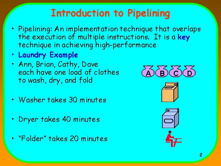
Introduction to Pipelining • Pipelining: An implementation technique that overlaps the execution of multiple instructions. It is a key technique in achieving high-performance • Laundry Example • Ann, Brian, Cathy, Dave each have one load of clothes A B C D to wash, dry, and fold • Washer takes 30 minutes • Dryer takes 40 minutes • “Folder” takes 20 minutes 2
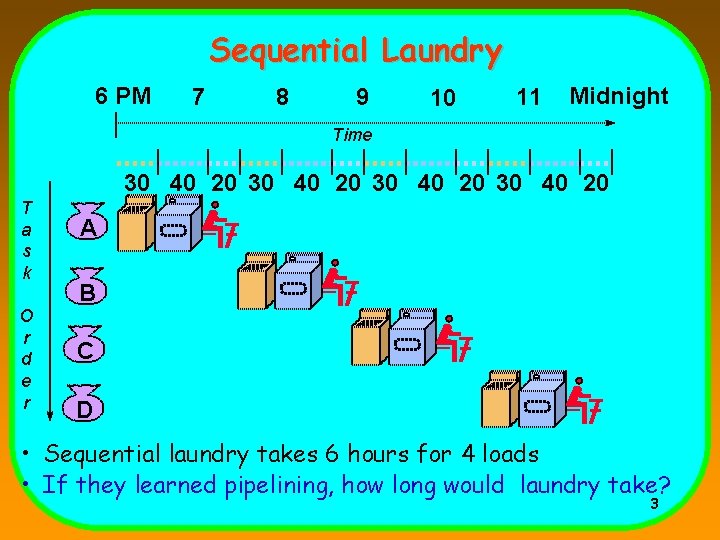
Sequential Laundry 6 PM 7 8 9 10 11 Midnight Time 30 40 20 T a s k O r d e r A B C D • Sequential laundry takes 6 hours for 4 loads • If they learned pipelining, how long would laundry take? 3
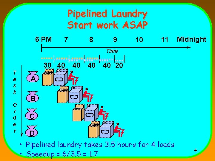
Pipelined Laundry Start work ASAP 6 PM 7 8 9 10 11 Midnight Time 30 40 T a s k O r d e r 40 40 40 20 A B C D • Pipelined laundry takes 3. 5 hours for 4 loads • Speedup = 6/3. 5 = 1. 7 4
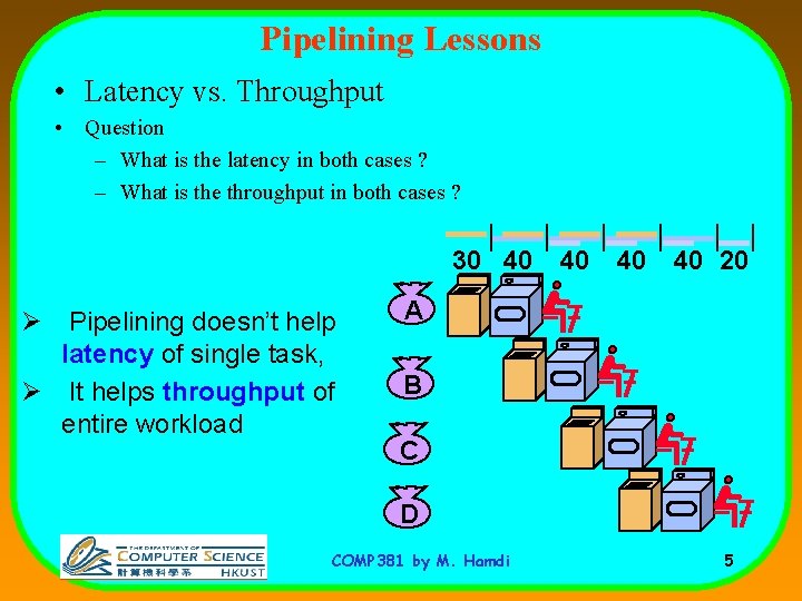
Pipelining Lessons • Latency vs. Throughput • Question – What is the latency in both cases ? – What is the throughput in both cases ? 30 40 Ø Pipelining doesn’t help latency of single task, Ø It helps throughput of entire workload 40 40 40 20 A B C D COMP 381 by M. Hamdi 5
![Pipelining Lessons [contd…] • Question – What is the fastest operation in the example](http://slidetodoc.com/presentation_image_h2/ee4cc37640e1a762b54af153a466cbc0/image-6.jpg "Pipelining Lessons [contd…] • Question – What is the fastest operation in the example")
Pipelining Lessons [contd…] • Question – What is the fastest operation in the example ? – What is the slowest operation in the example Pipeline rate limited by slowest pipeline stage 30 40 40 20 A B C D COMP 381 by M. Hamdi 6
![Pipelining Lessons [contd…] 30 40 A 40 40 40 20 Multiple tasks operating simultaneously](http://slidetodoc.com/presentation_image_h2/ee4cc37640e1a762b54af153a466cbc0/image-7.jpg "Pipelining Lessons [contd…] 30 40 A 40 40 40 20 Multiple tasks operating simultaneously")
Pipelining Lessons [contd…] 30 40 A 40 40 40 20 Multiple tasks operating simultaneously using different resources B C D COMP 381 by M. Hamdi 7
![Pipelining Lessons [contd…] • Question – Would the speedup increase if we had more](http://slidetodoc.com/presentation_image_h2/ee4cc37640e1a762b54af153a466cbc0/image-8.jpg "Pipelining Lessons [contd…] • Question – Would the speedup increase if we had more")
Pipelining Lessons [contd…] • Question – Would the speedup increase if we had more steps ? 30 40 A B 40 40 40 20 Potential Speedup = Number of pipe stages C D COMP 381 by M. Hamdi 8
![Pipelining Lessons [contd…] • Washer takes 30 minutes • Dryer takes 40 minutes •](http://slidetodoc.com/presentation_image_h2/ee4cc37640e1a762b54af153a466cbc0/image-9.jpg "Pipelining Lessons [contd…] • Washer takes 30 minutes • Dryer takes 40 minutes •")
Pipelining Lessons [contd…] • Washer takes 30 minutes • Dryer takes 40 minutes • “Folder” takes 20 minutes • Question – Will it affect if “Folder” also took 40 minutes Unbalanced lengths of pipe stages reduces speedup COMP 381 by M. Hamdi 9
![Pipelining Lessons [contd…] 30 40 40 20 A B C D Time to “fill”](http://slidetodoc.com/presentation_image_h2/ee4cc37640e1a762b54af153a466cbc0/image-10.jpg "Pipelining Lessons [contd…] 30 40 40 20 A B C D Time to “fill”")
Pipelining Lessons [contd…] 30 40 40 20 A B C D Time to “fill” pipeline and time to “drain” it reduces speedup COMP 381 by M. Hamdi 10
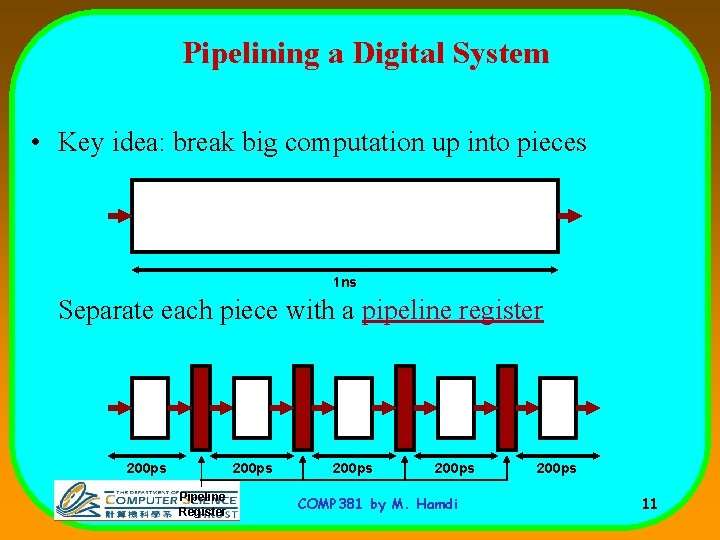
Pipelining a Digital System • Key idea: break big computation up into pieces 1 ns Separate each piece with a pipeline register 200 ps Pipeline Register 200 ps COMP 381 by M. Hamdi 200 ps 11
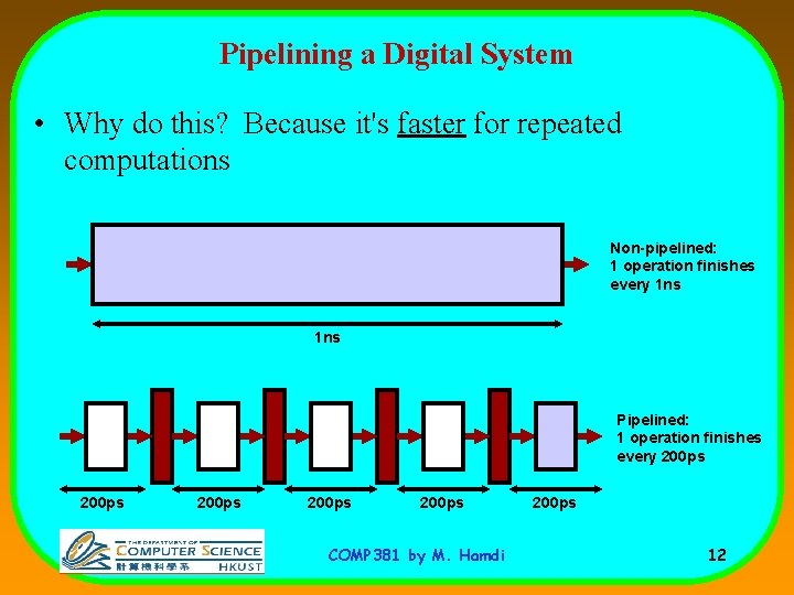
Pipelining a Digital System • Why do this? Because it's faster for repeated computations Non-pipelined: 1 operation finishes every 1 ns Pipelined: 1 operation finishes every 200 ps 200 ps COMP 381 by M. Hamdi 200 ps 12
Comments about pipelining • Pipelining increases throughput, but not latency – Answer available every 200 ps, BUT – A single computation still takes 1 ns • Limitations: – Computations must be divisible into stages of equal sizes – Pipeline registers add overhead COMP 381 by M. Hamdi 13
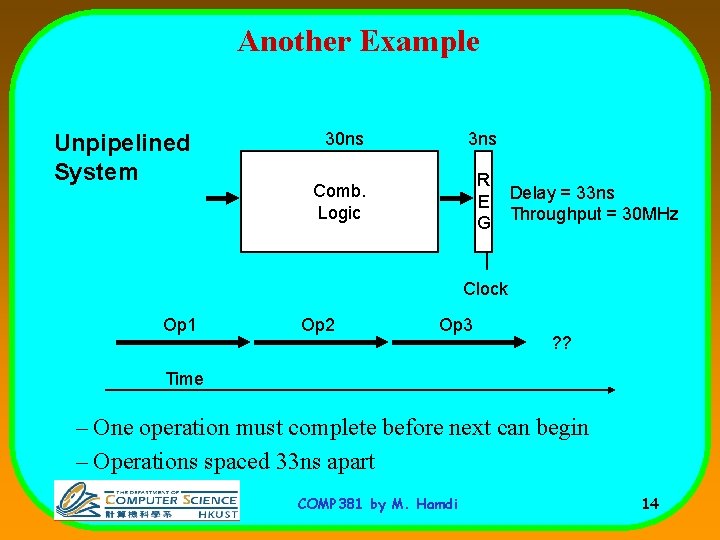
Another Example Unpipelined System 30 ns 3 ns Comb. Logic R E G Delay = 33 ns Throughput = 30 MHz Clock Op 1 Op 2 Op 3 ? ? Time – One operation must complete before next can begin – Operations spaced 33 ns apart COMP 381 by M. Hamdi 14
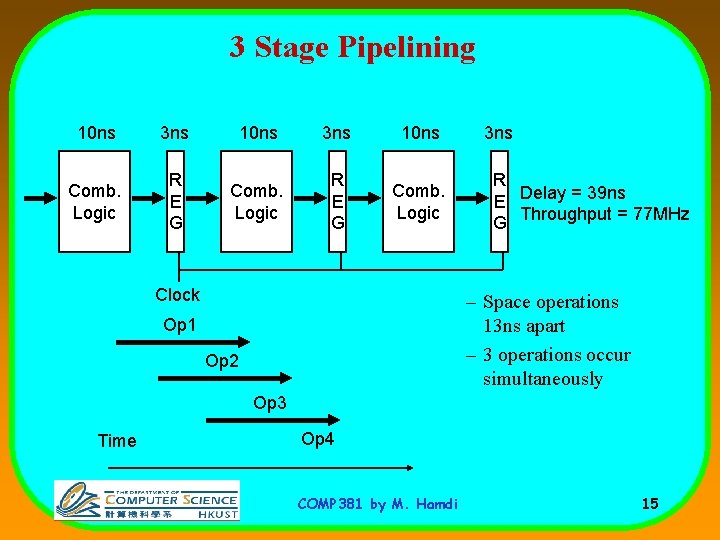
3 Stage Pipelining 10 ns 3 ns 10 ns Comb. Logic R E G Comb. Logic Clock 3 ns R E Delay = 39 ns G Throughput = 77 MHz – Space operations 13 ns apart – 3 operations occur simultaneously Op 1 Op 2 Op 3 Time Op 4 COMP 381 by M. Hamdi 15
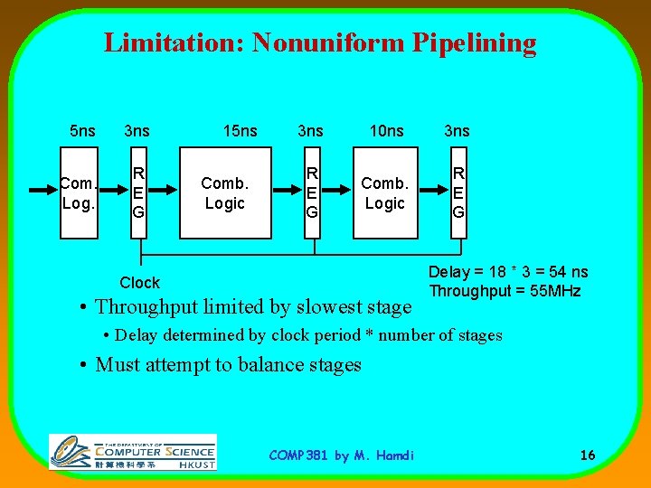
Limitation: Nonuniform Pipelining 5 ns 3 ns Com. Log. R E G 15 ns Comb. Logic 3 ns 10 ns 3 ns R E G Comb. Logic R E G Clock • Throughput limited by slowest stage Delay = 18 * 3 = 54 ns Throughput = 55 MHz • Delay determined by clock period * number of stages • Must attempt to balance stages COMP 381 by M. Hamdi 16
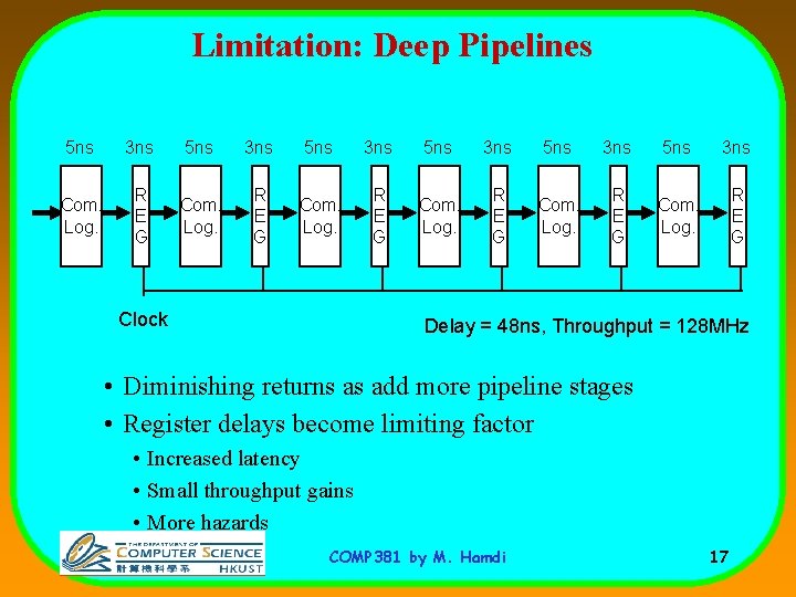
Limitation: Deep Pipelines 5 ns 3 ns 5 ns 3 ns Com. Log. R E G Clock Delay = 48 ns, Throughput = 128 MHz • Diminishing returns as add more pipeline stages • Register delays become limiting factor • Increased latency • Small throughput gains • More hazards COMP 381 by M. Hamdi 17
Computer (Processor) Pipelining • It is one KEY method of achieving High-Performance in • • • modern microprocessors It is being used in many different designs (not just processors) – http: //www. siliconstrategies. com/story/OEG 20020820 S 0054 It is a completely hardware mechanism A major advantage of pipelining over “parallel processing” is that it is not visible to the programmer An instruction execution pipeline involves a number of steps, where each step completes a part of an instruction. Each step is called a pipe stage or a pipe segment. COMP 381 by M. Hamdi 18
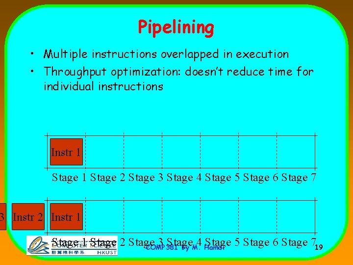
Pipelining • Multiple instructions overlapped in execution • Throughput optimization: doesn’t reduce time for individual instructions Instr 12 Stage 1 Stage 2 Stage 3 Stage 4 Stage 5 Stage 6 Stage 7 3 Instr 2 Instr 1 Stage 2 Stage 3 Stage 4 Stage 5 Stage 6 Stage 719 COMP 381 by M. Hamdi
Computer Pipelining • • • The stages or steps are connected one to the next to form a pipe -- instructions enter at one end and progress through the stage and exit at the other end. Throughput of an instruction pipeline is determined by how often an instruction exists the pipeline. The time to move an instruction one step down the line is equal to the machine cycle (Clock Rate) and is determined by the stage with the longest processing delay (slowest pipeline stage). COMP 381 by M. Hamdi 20
Pipelining: Design Goals • An important pipeline design consideration is to balance the length of each pipeline stage. • If all stages are perfectly balanced, then the time per instruction on a pipelined machine (assuming ideal conditions with no stalls): Time per instruction on unpipelined machine Number of pipe stages • Under these ideal conditions: – Speedup from pipelining equals the number of pipeline stages: – One instruction is completed every cycle, CPI = 1. COMP 381 by M. Hamdi 21 n,
Pipelining: Design Goals • Under these ideal conditions: – Speedup from pipelining equals the number of pipeline stages: n, – One instruction is completed every cycle, CPI = 1. – This is an asymptote of course, but +10% is commonly achieved – Difference is due to difficulty in achieving balanced stage design • Two ways to view the performance mechanism – Reduced CPI (i. e. non-piped to piped change) • Close to 1 instruction/cycle if you’re lucky – Reduced cycle-time (i. e. increasing pipeline depth) • Work split into more stages • Simpler stages result in faster clock cycles COMP 381 by M. Hamdi 22
Implementation of MIPS • We use the MIPS processor as an example to demonstrate the concepts of computer pipelining. • MIPS ISA is designed based on sound measurements and sound architectural considerations (as covered in class). • It is used by numerous companies (Nintendo and Playstation) through liscencing agreements. • These same concepts are being used by ALL other processors as well. COMP 381 by M. Hamdi 23
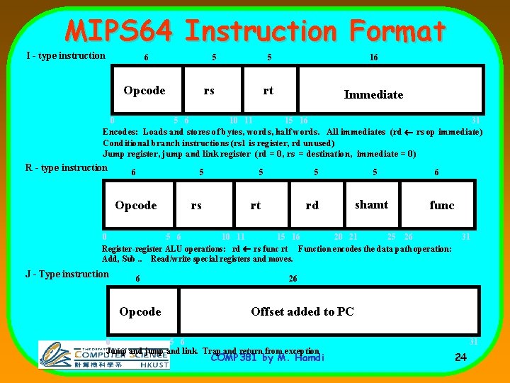
MIPS 64 Instruction Format I - type instruction 6 5 16 rs rt Immediate Opcode 5 0 5 6 10 11 15 16 31 Encodes: Loads and stores of bytes, words, half words. All immediates (rd ¬ rs op immediate) Conditional branch instructions (rs 1 is register, rd unused) Jump register, jump and link register (rd = 0, rs = destination, immediate = 0) R - type instruction 6 5 Opcode rs 5 5 rt rd 5 shamt 6 func 0 5 6 10 11 15 16 20 21 25 26 Register-register ALU operations: rd ¬ rs func rt Function encodes the data path operation: Add, Sub. . Read/write special registers and moves. J - Type instruction 6 Opcode 31 26 Offset added to PC 0 5 6 Jump and jump and link. Trap and return from exception COMP 381 by M. Hamdi 31 24
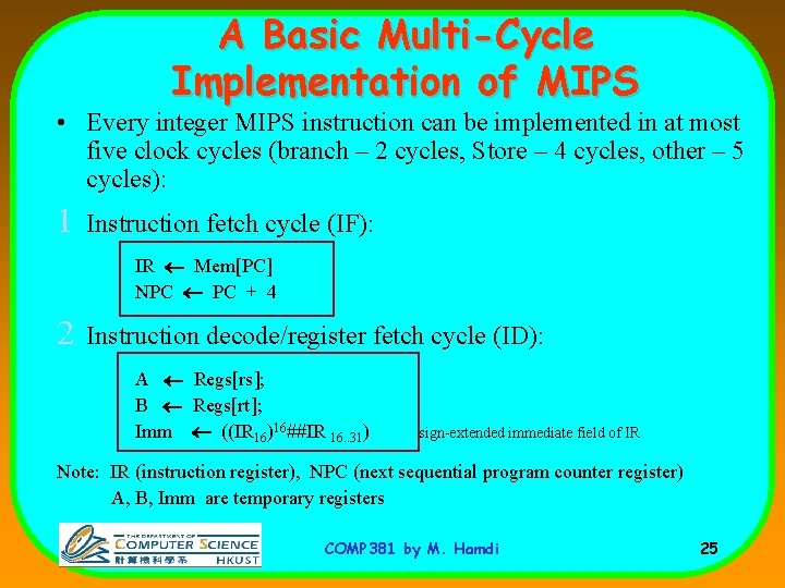
A Basic Multi-Cycle Implementation of MIPS • Every integer MIPS instruction can be implemented in at most five clock cycles (branch – 2 cycles, Store – 4 cycles, other – 5 cycles): 1 Instruction fetch cycle (IF): IR ¬ Mem[PC] NPC ¬ PC + 4 2 Instruction decode/register fetch cycle (ID): A ¬ Regs[rs]; B ¬ Regs[rt]; Imm ¬ ((IR 16)16##IR 16. . 31) sign-extended immediate field of IR Note: IR (instruction register), NPC (next sequential program counter register) A, B, Imm are temporary registers COMP 381 by M. Hamdi 25
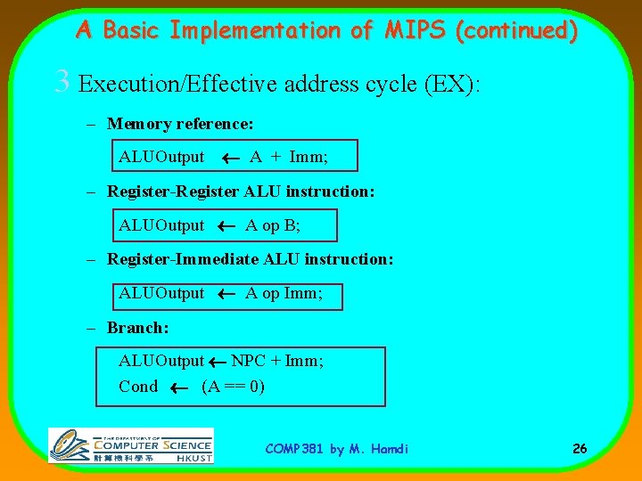
A Basic Implementation of MIPS (continued) 3 Execution/Effective address cycle (EX): – Memory reference: ALUOutput ¬ A + Imm; – Register-Register ALU instruction: ALUOutput ¬ A op B; – Register-Immediate ALU instruction: ALUOutput ¬ A op Imm; – Branch: ALUOutput ¬ NPC + Imm; Cond ¬ (A == 0) COMP 381 by M. Hamdi 26
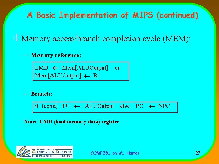
A Basic Implementation of MIPS (continued) 4 Memory access/branch completion cycle (MEM): – Memory reference: LMD ¬ Mem[ALUOutput] ¬ B; or – Branch: if (cond) PC ¬ ALUOutput else PC ¬ NPC Note: LMD (load memory data) register COMP 381 by M. Hamdi 27
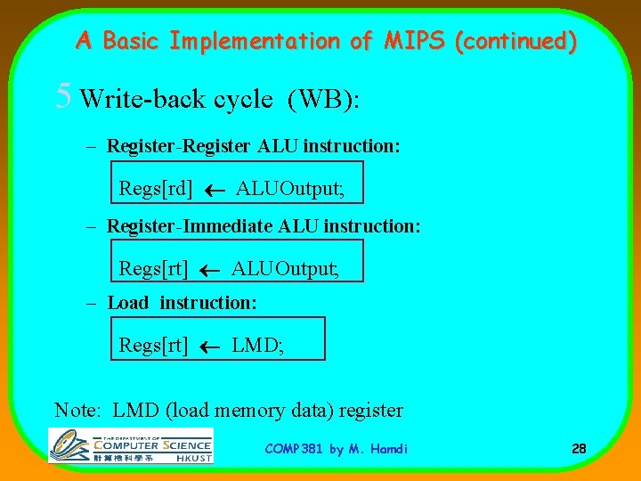
A Basic Implementation of MIPS (continued) 5 Write-back cycle (WB): – Register-Register ALU instruction: Regs[rd] ¬ ALUOutput; – Register-Immediate ALU instruction: Regs[rt] ¬ ALUOutput; – Load instruction: Regs[rt] ¬ LMD; Note: LMD (load memory data) register COMP 381 by M. Hamdi 28
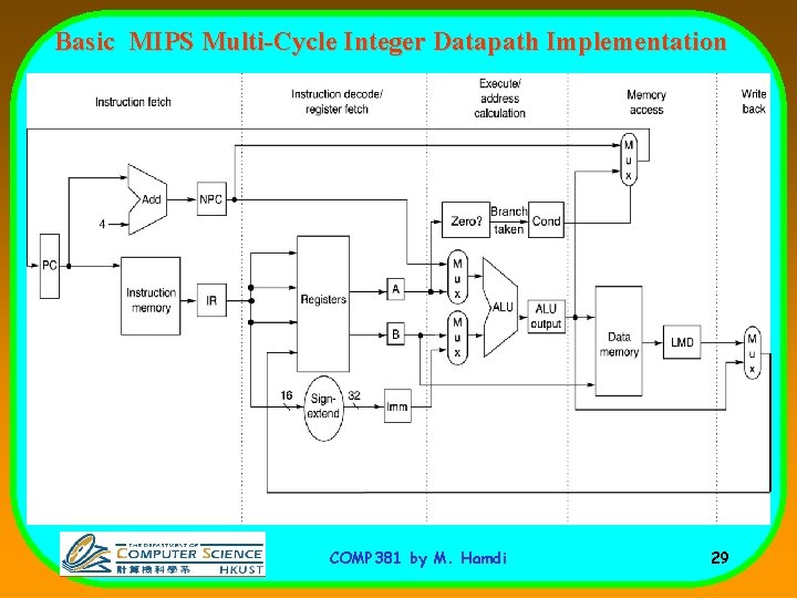
Basic MIPS Multi-Cycle Integer Datapath Implementation COMP 381 by M. Hamdi 29
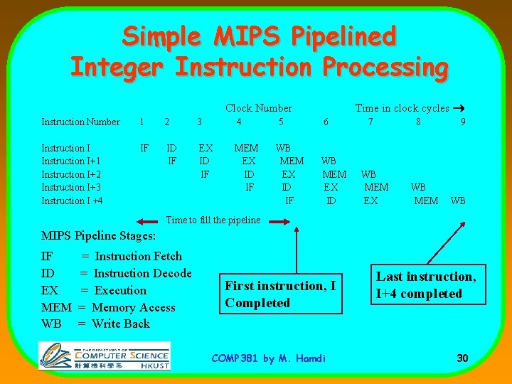
Simple MIPS Pipelined Integer Instruction Processing Time in clock cycles ® Clock Number Instruction Number 1 2 3 4 5 6 Instruction I+1 Instruction I+2 Instruction I+3 Instruction I +4 IF ID IF EX ID IF MEM EX ID IF WB MEM EX ID 7 8 WB MEM EX WB MEM 9 WB Time to fill the pipeline MIPS Pipeline Stages: IF ID EX MEM WB = Instruction Fetch = Instruction Decode = Execution = Memory Access = Write Back First instruction, I Completed COMP 381 by M. Hamdi Last instruction, I+4 completed 30
Pipelining The MIPS Processor • There are 5 steps in instruction execution: 1. Instruction Fetch 2. Instruction Decode and Register Read 3. Execution operation or calculate address 4. Memory access 5. Write result into register COMP 381 by M. Hamdi 31
![Datapath for Instruction Fetch Instruction <- MEM[PC] PC <- PC + 4 COMP 381](http://slidetodoc.com/presentation_image_h2/ee4cc37640e1a762b54af153a466cbc0/image-32.jpg "Datapath for Instruction Fetch Instruction <- MEM[PC] PC <- PC + 4 COMP 381")
Datapath for Instruction Fetch Instruction <- MEM[PC] PC <- PC + 4 COMP 381 by M. Hamdi 32
![Datapath for R-Type Instructions add rd, rs, rt R[rd] <- R[rs] + R[rt]; COMP](http://slidetodoc.com/presentation_image_h2/ee4cc37640e1a762b54af153a466cbc0/image-33.jpg "Datapath for R-Type Instructions add rd, rs, rt R[rd] <- R[rs] + R[rt]; COMP")
Datapath for R-Type Instructions add rd, rs, rt R[rd] <- R[rs] + R[rt]; COMP 381 by M. Hamdi 33
![Datapath for Load/Store Instructions lw rt, offset(rs) R[rt] <- MEM[R[rs] + s_extend(offset)]; COMP 381](http://slidetodoc.com/presentation_image_h2/ee4cc37640e1a762b54af153a466cbc0/image-34.jpg "Datapath for Load/Store Instructions lw rt, offset(rs) R[rt] <- MEM[R[rs] + s_extend(offset)]; COMP 381")
Datapath for Load/Store Instructions lw rt, offset(rs) R[rt] <- MEM[R[rs] + s_extend(offset)]; COMP 381 by M. Hamdi 34
![Datapath for Load/Store Instructions sw rt, offset(rs) MEM[R[rs] + sign_extend(offset)] <- R[rt] COMP 381](http://slidetodoc.com/presentation_image_h2/ee4cc37640e1a762b54af153a466cbc0/image-35.jpg "Datapath for Load/Store Instructions sw rt, offset(rs) MEM[R[rs] + sign_extend(offset)] <- R[rt] COMP 381")
Datapath for Load/Store Instructions sw rt, offset(rs) MEM[R[rs] + sign_extend(offset)] <- R[rt] COMP 381 by M. Hamdi 35
![Datapath for Branch Instructions beq rs, rt, offset if (R[rs] == R[rt]) then PC](http://slidetodoc.com/presentation_image_h2/ee4cc37640e1a762b54af153a466cbc0/image-36.jpg "Datapath for Branch Instructions beq rs, rt, offset if (R[rs] == R[rt]) then PC")
Datapath for Branch Instructions beq rs, rt, offset if (R[rs] == R[rt]) then PC <- PC+4 + s_extend(offset<<2) COMP 381 by M. Hamdi 36
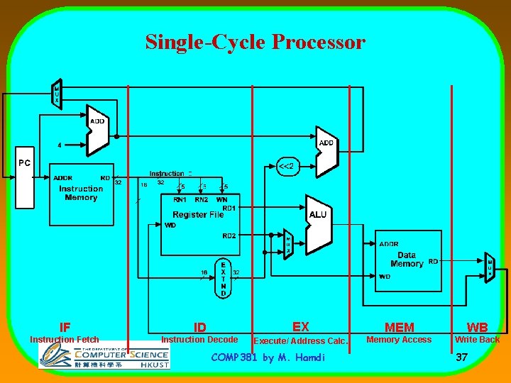
Single-Cycle Processor IF ID EX MEM WB Instruction Fetch Instruction Decode Execute/ Address Calc. Memory Access Write Back COMP 381 by M. Hamdi 37
Pipelining - Key Idea • Question: What happens if we break execution into multiple cycles? • Answer: in the best case, we can start executing a new instruction on each clock cycle this is pipelining • Pipelining stages: – – – IF - Instruction Fetch ID - Instruction Decode EX - Execute / Address Calculation MEM - Memory Access (read / write) WB - Write Back (results into register file) COMP 381 by M. Hamdi 38
Pipeline Registers • Pipeline registers are named with 2 stages (the stages that the register is “between. ”) • ANY information needed in a later pipeline stage MUST be passed via a pipeline register – Example: IF/ID register gets • • instruction • PC+4 No register is needed after WB. Results from the WB stage are already stored in the register file, which serves as a pipeline register between instructions. COMP 381 by M. Hamdi 39
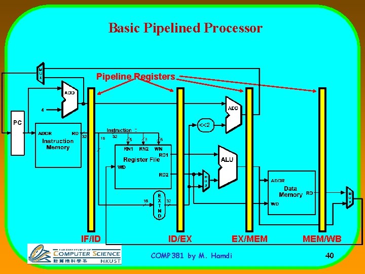
Basic Pipelined Processor Pipeline Registers IF/ID ID/EX EX/MEM COMP 381 by M. Hamdi MEM/WB 40
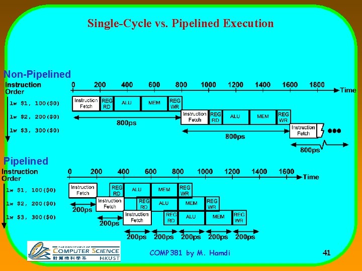
Single-Cycle vs. Pipelined Execution Non-Pipelined COMP 381 by M. Hamdi 41
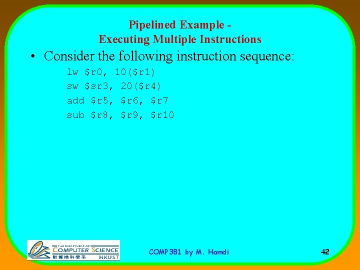
Pipelined Example Executing Multiple Instructions • Consider the following instruction sequence: lw $r 0, 10($r 1) sw $sr 3, 20($r 4) add $r 5, $r 6, $r 7 sub $r 8, $r 9, $r 10 COMP 381 by M. Hamdi 42
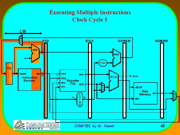
Executing Multiple Instructions Clock Cycle 1 LW COMP 381 by M. Hamdi 43
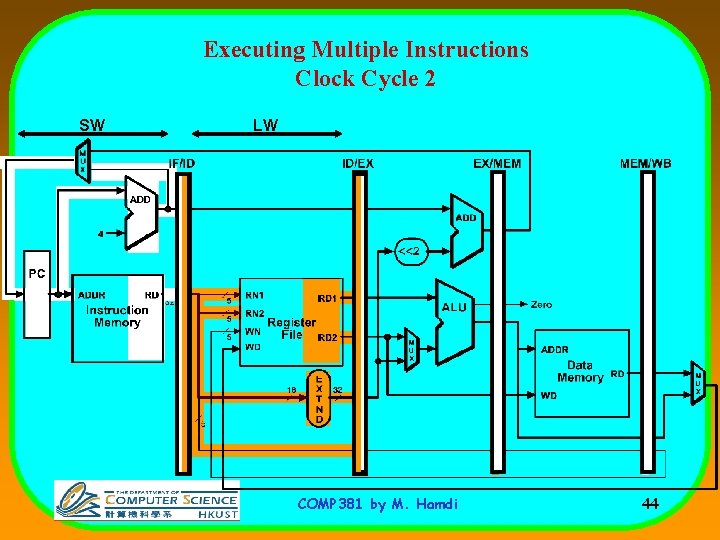
Executing Multiple Instructions Clock Cycle 2 SW LW COMP 381 by M. Hamdi 44
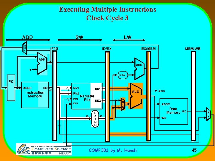
Executing Multiple Instructions Clock Cycle 3 ADD SW LW COMP 381 by M. Hamdi 45
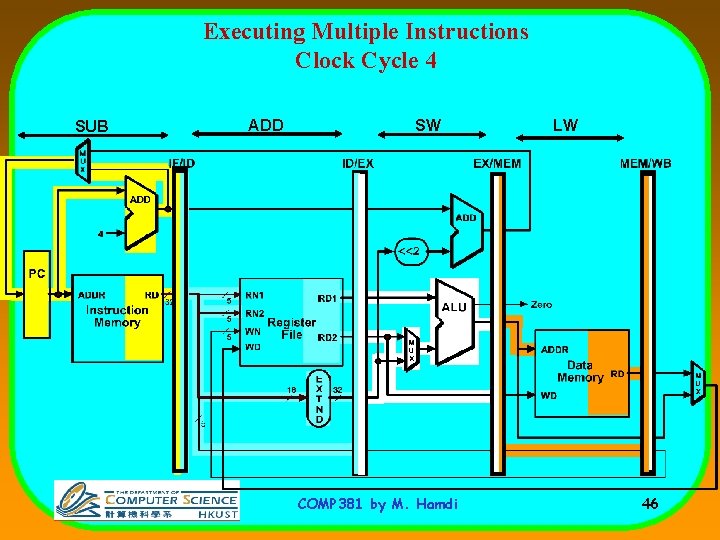
Executing Multiple Instructions Clock Cycle 4 SUB ADD SW COMP 381 by M. Hamdi LW 46
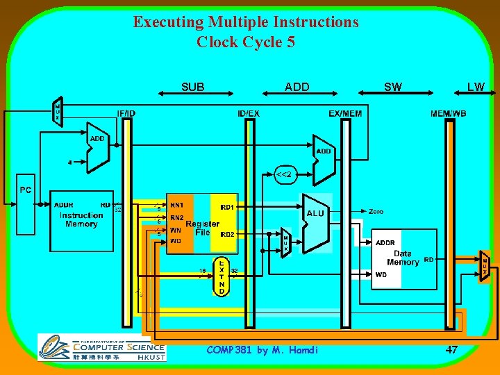
Executing Multiple Instructions Clock Cycle 5 SUB ADD COMP 381 by M. Hamdi SW LW 47
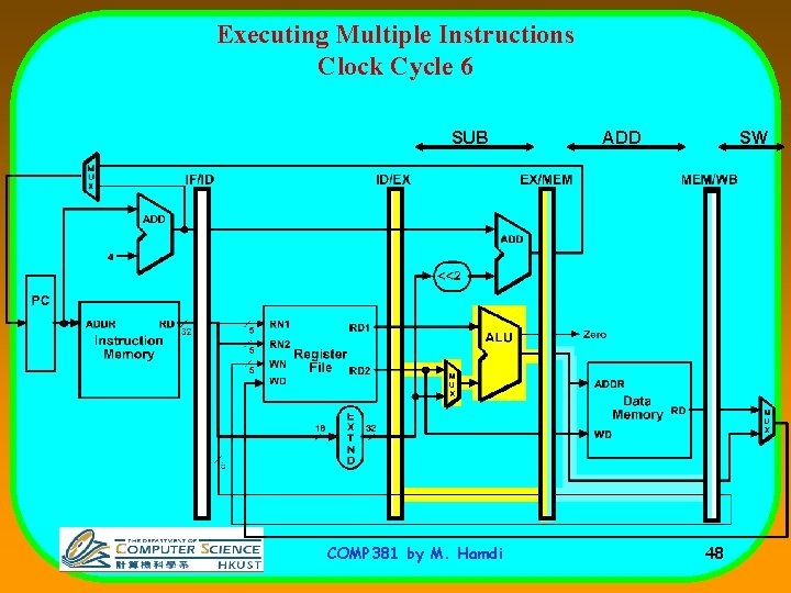
Executing Multiple Instructions Clock Cycle 6 SUB COMP 381 by M. Hamdi ADD SW 48
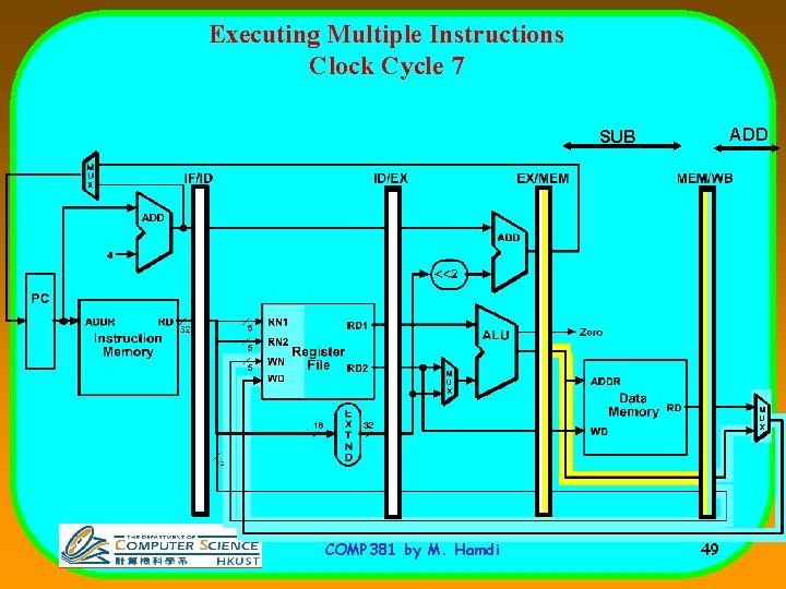
Executing Multiple Instructions Clock Cycle 7 ADD SUB COMP 381 by M. Hamdi 49
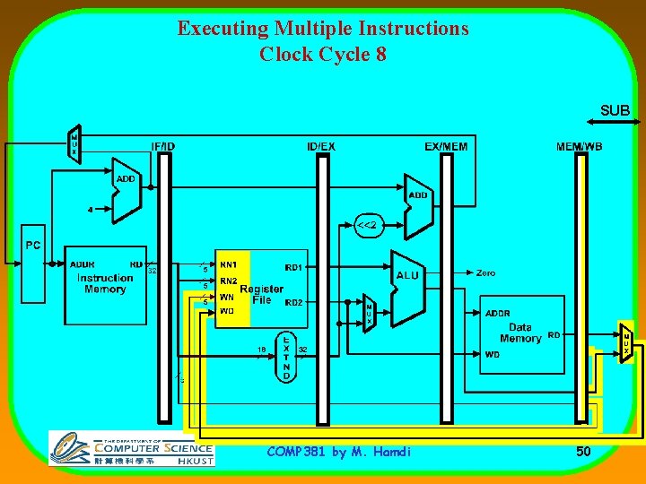
Executing Multiple Instructions Clock Cycle 8 SUB COMP 381 by M. Hamdi 50
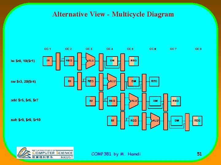
Alternative View - Multicycle Diagram COMP 381 by M. Hamdi 51
Pipelining: Design Goals • Two ways to view the performance mechanism – Reduced CPI (i. e. non-piped to piped change) • Close to 1 instruction/cycle if you’re lucky – Reduced cycle-time (i. e. increasing pipeline depth) • Work split into more stages • Simpler stages result in faster clock cycles COMP 381 by M. Hamdi 52
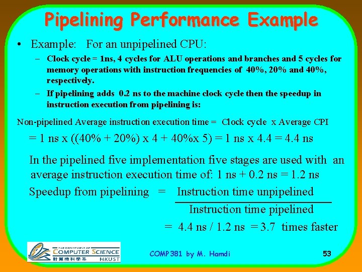
Pipelining Performance Example • Example: For an unpipelined CPU: – Clock cycle = 1 ns, 4 cycles for ALU operations and branches and 5 cycles for memory operations with instruction frequencies of 40%, 20% and 40%, respectively. – If pipelining adds 0. 2 ns to the machine clock cycle then the speedup in instruction execution from pipelining is: Non-pipelined Average instruction execution time = Clock cycle x Average CPI = 1 ns x ((40% + 20%) x 4 + 40%x 5) = 1 ns x 4. 4 = 4. 4 ns In the pipelined five implementation five stages are used with an average instruction execution time of: 1 ns + 0. 2 ns = 1. 2 ns Speedup from pipelining = Instruction time unpipelined Instruction time pipelined = 4. 4 ns / 1. 2 ns = 3. 7 times faster COMP 381 by M. Hamdi 53
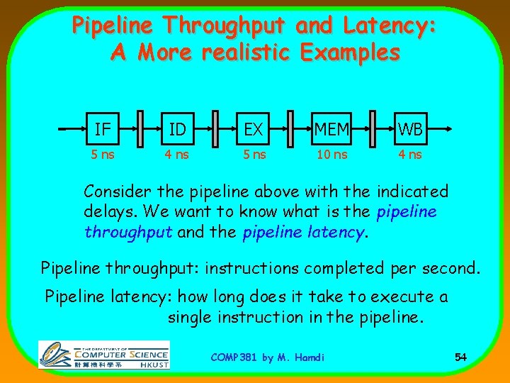
Pipeline Throughput and Latency: A More realistic Examples IF ID EX MEM WB 5 ns 4 ns 5 ns 10 ns 4 ns Consider the pipeline above with the indicated delays. We want to know what is the pipeline throughput and the pipeline latency. Pipeline throughput: instructions completed per second. Pipeline latency: how long does it take to execute a single instruction in the pipeline. COMP 381 by M. Hamdi 54
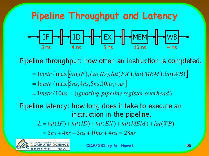
Pipeline Throughput and Latency IF ID EX MEM WB 5 ns 4 ns 5 ns 10 ns 4 ns Pipeline throughput: how often an instruction is completed. Pipeline latency: how long does it take to execute an instruction in the pipeline. COMP 381 by M. Hamdi 55
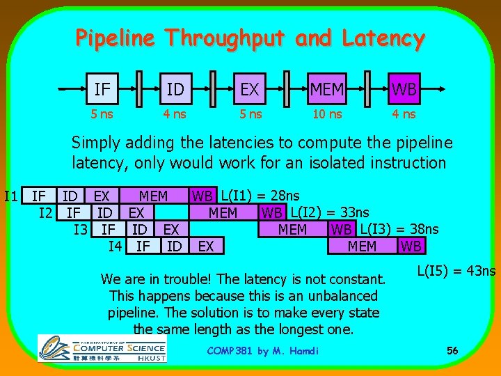
Pipeline Throughput and Latency IF ID EX MEM WB 5 ns 4 ns 5 ns 10 ns 4 ns Simply adding the latencies to compute the pipeline latency, only would work for an isolated instruction I 1 IF ID EX MEM WB L(I 1) = 28 ns I 2 IF ID EX MEM WB L(I 2) = 33 ns I 3 IF ID EX MEM WB L(I 3) = 38 ns MEM WB I 4 IF ID EX We are in trouble! The latency is not constant. This happens because this is an unbalanced pipeline. The solution is to make every state the same length as the longest one. COMP 381 by M. Hamdi L(I 5) = 43 ns 56
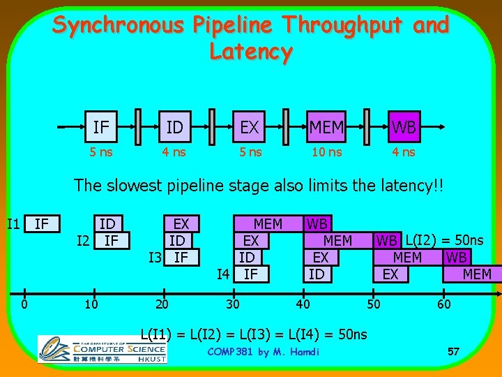
Synchronous Pipeline Throughput and Latency IF ID EX MEM WB 5 ns 4 ns 5 ns 10 ns 4 ns The slowest pipeline stage also limits the latency!! I 1 IF 0 ID I 2 IF 10 EX ID I 3 IF 20 MEM EX ID I 4 IF 30 WB MEM EX ID 40 WB L(I 2) = 50 ns MEM WB EX MEM 50 60 L(I 1) = L(I 2) = L(I 3) = L(I 4) = 50 ns COMP 381 by M. Hamdi 57
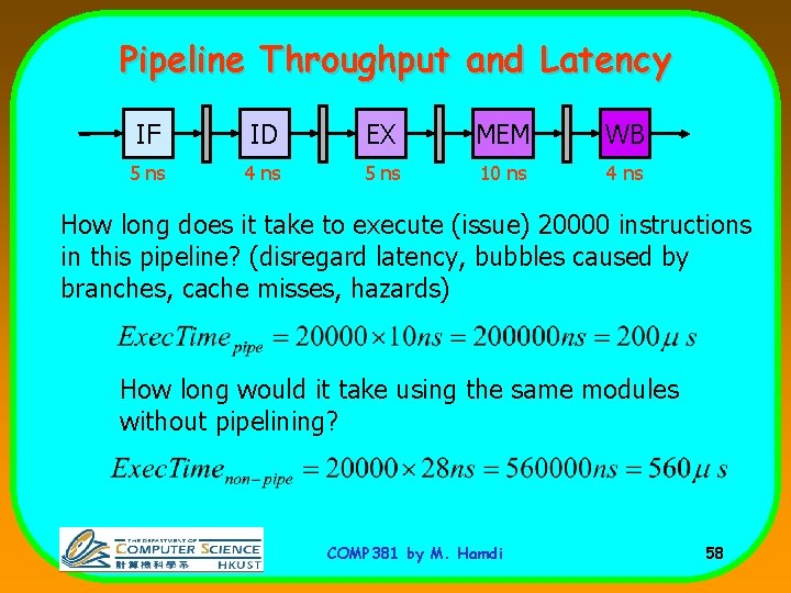
Pipeline Throughput and Latency IF ID EX MEM WB 5 ns 4 ns 5 ns 10 ns 4 ns How long does it take to execute (issue) 20000 instructions in this pipeline? (disregard latency, bubbles caused by branches, cache misses, hazards) How long would it take using the same modules without pipelining? COMP 381 by M. Hamdi 58
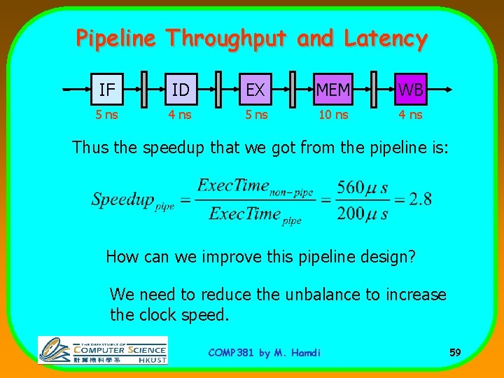
Pipeline Throughput and Latency IF ID EX MEM WB 5 ns 4 ns 5 ns 10 ns 4 ns Thus the speedup that we got from the pipeline is: How can we improve this pipeline design? We need to reduce the unbalance to increase the clock speed. COMP 381 by M. Hamdi 59
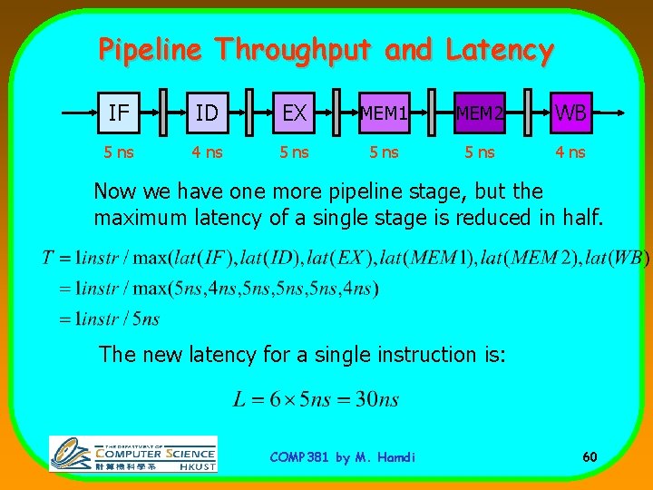
Pipeline Throughput and Latency IF ID EX MEM 1 MEM 2 WB 5 ns 4 ns 5 ns 4 ns Now we have one more pipeline stage, but the maximum latency of a single stage is reduced in half. The new latency for a single instruction is: COMP 381 by M. Hamdi 60
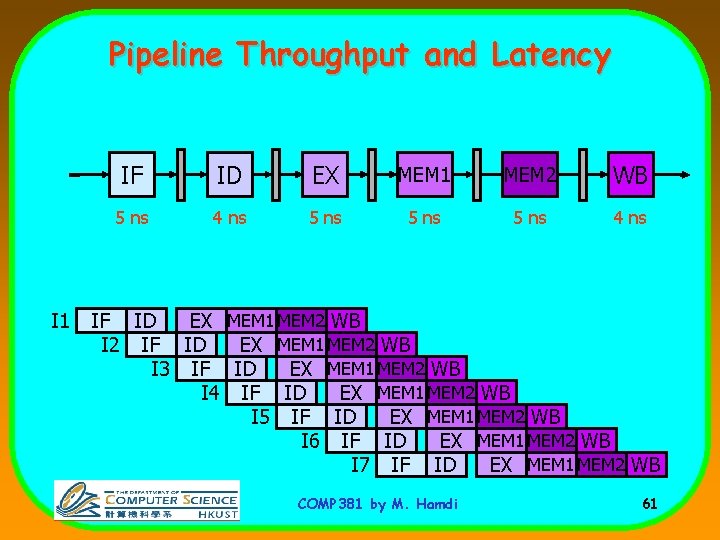
Pipeline Throughput and Latency I 1 IF ID EX MEM 1 MEM 2 WB 5 ns 4 ns 5 ns 4 ns IF ID EX MEM 1 MEM 2 WB I 2 IF ID EX MEM 1 MEM 2 WB I 3 IF ID EX MEM 1 MEM 2 WB I 4 IF ID EX MEM 1 MEM 2 WB I 5 IF ID EX MEM 1 MEM 2 WB I 6 IF ID EX MEM 1 MEM 2 WB I 7 IF ID EX MEM 1 MEM 2 WB COMP 381 by M. Hamdi 61
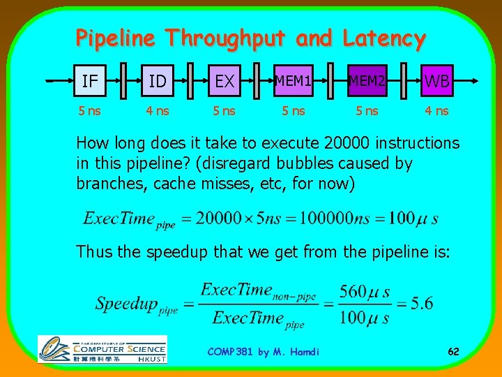
Pipeline Throughput and Latency IF ID EX MEM 1 MEM 2 WB 5 ns 4 ns 5 ns 4 ns How long does it take to execute 20000 instructions in this pipeline? (disregard bubbles caused by branches, cache misses, etc, for now) Thus the speedup that we get from the pipeline is: COMP 381 by M. Hamdi 62
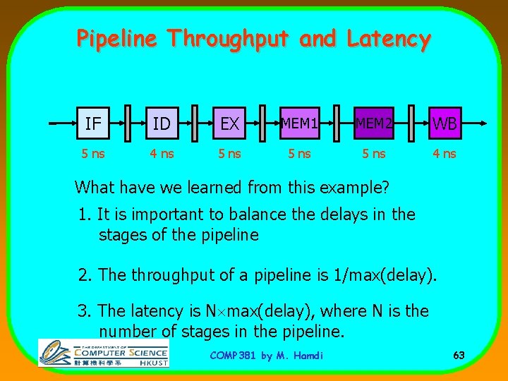
Pipeline Throughput and Latency IF ID EX MEM 1 MEM 2 WB 5 ns 4 ns 5 ns 4 ns What have we learned from this example? 1. It is important to balance the delays in the stages of the pipeline 2. The throughput of a pipeline is 1/max(delay). 3. The latency is N max(delay), where N is the number of stages in the pipeline. COMP 381 by M. Hamdi 63
Pipelining is Not That Easy for Computers • Limits to pipelining: Hazards prevent next instruction from executing during its designated clock cycle – Structural hazards: Arise from hardware resource conflicts when the available hardware cannot support all possible combinations of instructions. – Data hazards: Arise when an instruction depends on the results of a previous instruction in a way that is exposed by the overlapping of instructions in the pipeline – Control hazards: Arise from the pipelining of conditional branches and other instructions that change the PC • A possible solution is to “stall” the pipeline until the hazard is resolved, inserting one or more “bubbles” in the pipeline COMP 381 by M. Hamdi 64
- Slides: 64