Implementing interrupt driven IO Why use interrupt driven


UART ISR CODE")


- Slides: 15
Implementing interrupt driven IO
Why use interrupt driven IO? • Positive points – Allows asynchronous operation of IO events – Good use of resources – Leads to modular structure of system – Leads to better response times for interactive tasks • Negative points – It is harder to program – Leads to more complex code and system – Can be difficult to debug errors – Could have security implications
Hardware resources required • We will need a processor which can accept interrupts • A serial port module that can generate interrupts • A priority scheme would be useful • At least bi-modal processor – at least supervisor and user modes
The 68307 Serial module
UART Mode Register 1 • Rx. IRQ—Receiver Interrupt Select – 1 = FFULL is the source that generates IRQ. – 0 = Rx. RDY is the source that generates IRQ.
UART Interrupt Status Register • • Rx. RDY—Receiver Ready or FIFO Full – The function of this bit is programmed by UMR 1 bit 6. It is a duplicate of either the FFULL or Rx. RDY bit of USR. Tx. RDY—Transmitter Ready – This bit is the duplication of the Tx. RDY bit in USR. – 1 = The transmitter holding register is empty and ready to be loaded with a character. – 0 = The transmitter holding register was loaded by the CPU, or the transmitter is disabled. – Characters loaded into the transmitter holding register when Tx. RDY=0 are not transmitted.
UART Interrupt Mask Register • FFULL—FIFO Full – 1 = Enable interrupt – 0 = Disable interrupt • Tx. RDY—Transmitter Ready – 1 = Enable interrupt – 0 = Disable interrupt
UART Interrupt Vector Register • IVR 7–IVR 0—Interrupt Vector Bits – This 8 -bit number indicates the offset from the base of the vector table where the address of the exception handler for the specified interrupt is located. The UIVR is reset to $0 F, which indicates an uninitialized interrupt condition.
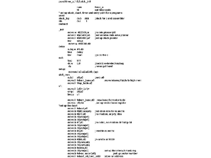
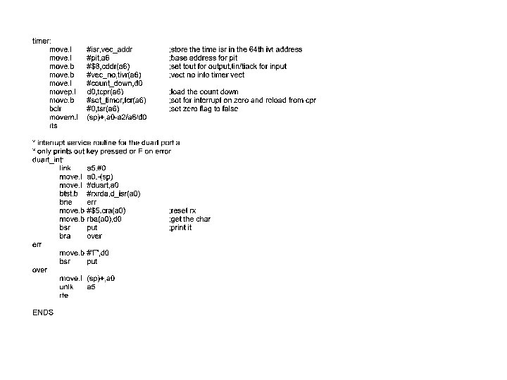
(D)UART ISR CODE
Library and System IO calls • Library and system IO calls do not write to the IO devices. They write to internal operating system buffers. • These buffers are in – User space for library buffers – fprintf etc – In system space for system calls – write, read etc • This allows processes to read and write data off-line from peripherals
IOCTL or IO control functions • As there is a separation between the calls that handle the hardware and handle the data buffers, the operating system can process the data quite easily running a series of control functions on the data. • In Unix/Linux these are called IOCTL calls. For example – stty -raw
Writing data from user space to a device User Space System/kernel space Printf “data” Write D A T A Buffer Sys_write D A T A Buffer IOCTL Functions DEVICE
Connecting Processes with their IO • In multi-tasking and multi-user systems there a number of users and processes waiting to send or receive data. • The operating systems must make sure that they get their correct data or that it goes to the correct resource • This is handled by the scheduler and IO manager modules.