IMAGING METHODS IN DENTISTRY Radiography Magnetic Resonance Imaging

 Creating 3 D images as 2 D photography")


 thin radiopaque (white) area around")
 area on the crown of the teeth Dentine, Cementum less")

 § Panoramic extraoral technique § Used to examine both jaws, TMJ,")


- Slides: 56
IMAGING METHODS IN DENTISTRY Radiography Magnetic Resonance Imaging Ultrasonography
Summation imaging - X ray (RTG) Creating 3 D images as 2 D photography Storeyed imaging - CT, MRI, Ultrasonography (USG) 2 D image, third dimension is width of layer
Radiography Conventional x digital radiography I. Intraoral II. Extraoral III. Specific IV. Contrast imaging V. CT diagnostic
Conventional Radiography § Conventional intra-oral radiographic film consists of silver halide grains in a gelatine matrix § When this film is exposed to X-ray photons the silver halide crystals are sensitized and are reduced to black during the developing process § The film acts as both the radiation detector and the image display
Digital Radiography § Using pixels or small light sensitive elements, can be a range of shades of grey depending on the exposure, and are arranged in grids and rows on the sensor § The sensors are only the radiation detector and the image is displayed on a monitor
Advantages of digital imaging: § Dose reductions of up to 90% § The greatest advantage of digital imaging over conventional film is image manipulation § Contrast enhancement can effectively compensate for over or under exposure of the digital image § Other advantages: 3 D reconstruction, time, storage, environmentally friendly
I. INTRAORAL RADIOGRAPHY Gives graphic information about the alveolar bone, periodontal areas and the hard tissues of the tooth 1. Bisecting technique 2. Paralleling technique 3. Bitewing technique 4. Occlusal radiograph
1. Bisecting Technique Central ray is directed at an imaginary line that bisects the angle created by the long axis of the tooth and the film CR perpendicular to bisecting line Long axis of tooth Bisecting line Film plane
Film will be in right angles to the beam → isometric Isometric An acute angle → hypometric (teeth shortened) An obtuse angle → hypermetric (teeth elongated)
Horizontal angulation - the central ray must be directed through the interproximal space between the teeth under examination → ortoradial picture Orthoradial Eccentric projection (mesio- or disto-) is useful for information about shape and lenght of the root canals
2. Paralleling Technique Position of the film: the long axis of the film is parallel with the long axis of the teeth CR perpendicular to long axis of tooth & film Long axis of tooth Film parallel to long axis of tooth
The X-ray film is placed into a X-ray film holder
3. Bite Wing Technique § Examine the interproximal surfaces of teeth § The film is placed parallel to the crowns of both teeth and stabilized by film holder or by bite wing tab ay r Central Bend of film Bite-wing tab
§ Horizontal × Vertical bite wing § Vertical bite wing generally more informative than horizontal in detecting moderate to severe periodontal disease and can also be taken in anterior region Vertical Horizontal
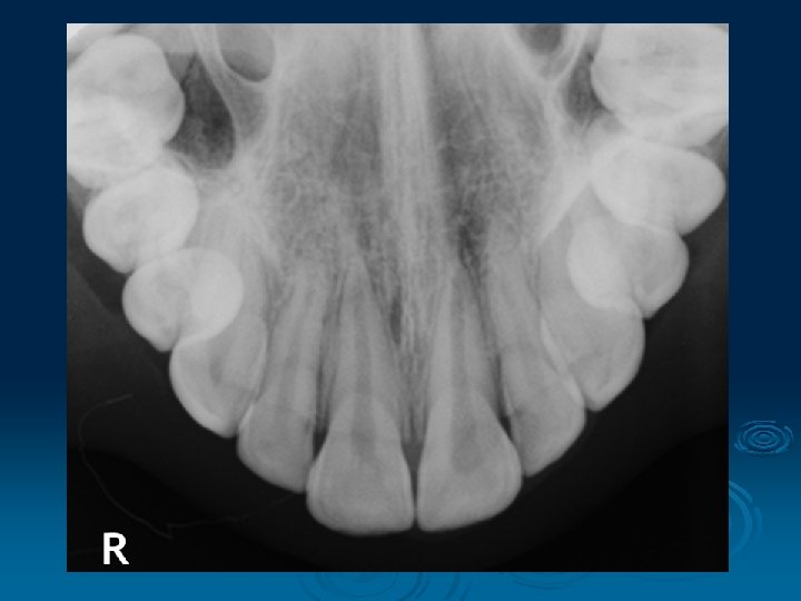
4. Occlusal Radiograph § A highly detailed x-ray taken with the x-ray plate placed between your teeth § It is useful to look closely at the front teeth (top or bottom) to check for any extra teeth or pathology § A special type of occlusal radiography technique can help demonstrate stones in the salivary glands in the floor of the mouth
Full-Mouth X-Ray
Reading of x ray picture Compact bone (lamina dura) thin radiopaque (white) area around tooth Spongy bone netting structure
Enamel A radiopaque (white) area on the crown of the teeth Dentine, Cementum less radiopaque than enamel, just inferior to it Pulp chamber A radiolucent (dark) area surrounded by dentin Periodontal slit A radiolucent area that surrounds the root(s)
II. EXTRAORAL RADIOGRAPHY 1. Orthopantomogra phy 2. Cephalometry 3. Conventional
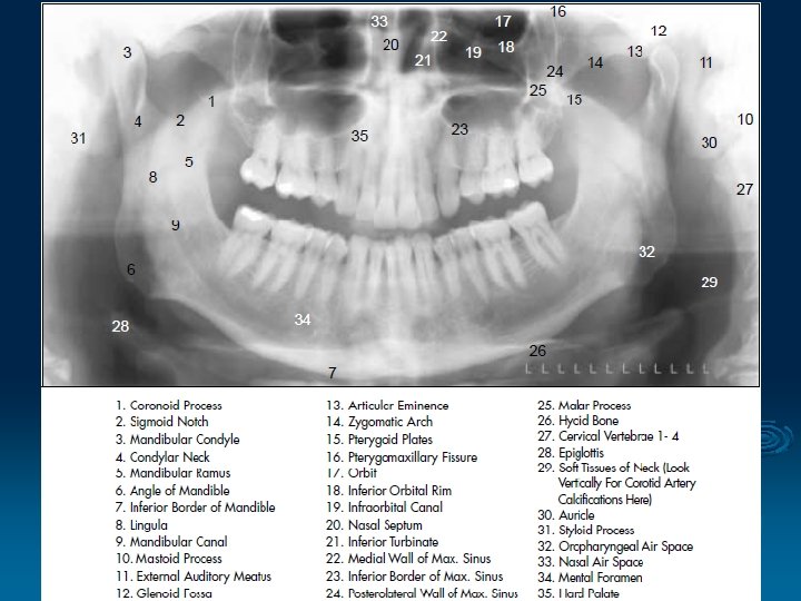
1. Orthopantomography (OPG) § Panoramic extraoral technique § Used to examine both jaws, TMJ, maxillary sinuses and the teeth on a single image § Convenient and inexpensive method with low radiation exposure
Extraoral film = indirect exposure type film § The energy of the x-ray beam is converted into light by intensifying screens (the film is sandwisched between two screens) and this light is used to expose photographic type film § Orthoradial projection – minimizes crown overlapping
§ Patient is positioned with the Franfort plane horizontal, bite peg between the anterior teeth and the chin positioned on the chin support § The film and the tubehead rotate around the patient and produce a series of individual images in a single film
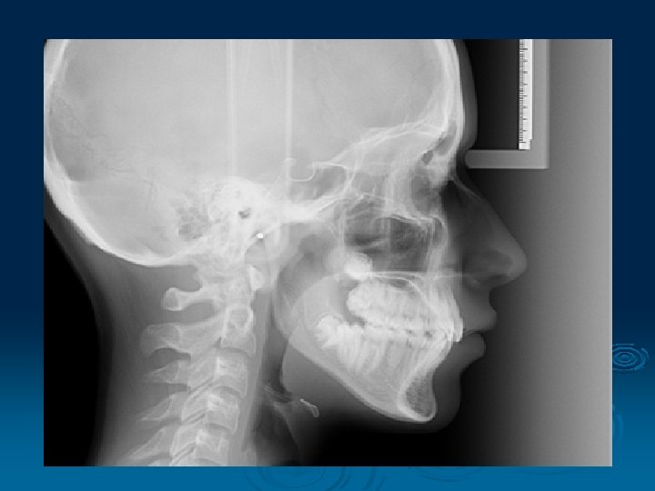
2. Cephalometry § A standardized and reproducible form of skull radiography used extensively in orthodontics to assess the relationships of the teeth to the jaws and the jaws to the rest of the facial skeleton § Main indications - monitoring treatment progress, preoperative evaluation of skeletal and soft tissue patterns, postoperative appraisal of the results of surgery and long-term follow-up studies
§ The pacient is positioned within the cephalostat with the Frankfort plane horizontal, teeth should be in maximum intercuspation § The head is immobilized within the apparatus with the plastic ear rods being inserted into the external auditory meati § The x-ray beam is horizontal and centred on the ear rods § Soft x-rays
Main radiographic projections: lateral PA jaws
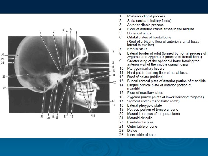
3. Conventional Radiography Skull projection: Lateral Postero-anterior Facial projection: Submento-vertical Hirtz Waters Clementschitsch
Lateral Projection
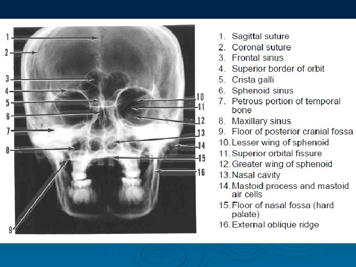
Postero-Anterior Projection
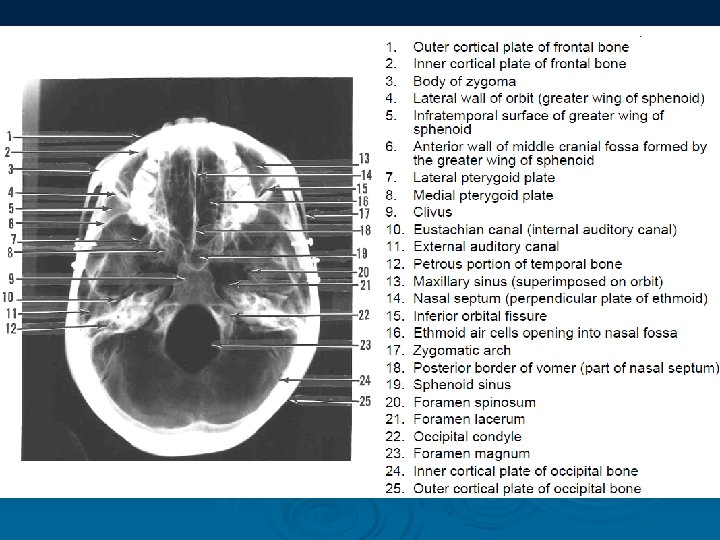
Submento-Vertical Projection
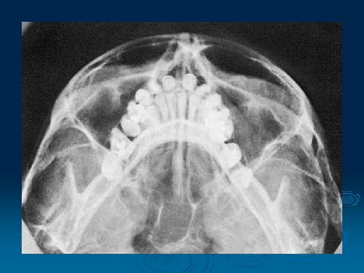
Hirtz' Projection § The vertical submental projection § The central ray is centred between the angles of the jaw the mandibular arch and condyles, the skull base, sphenoid sinus and the posterior ethmoid cells
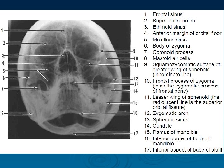
Waters Technique § Postero-anterior projection § The paranasal sinuses, orbital floor, orbital rim, mandible zygomatic arch and temporal line determine a possible fluid level indicative of sinusitis or soft tissue proliferations within sinus
Clementschitsch View
III. SPECIFIC RADIOGRAPHY § Stenvers projection § Schullers projection § Alber-Schonberg view
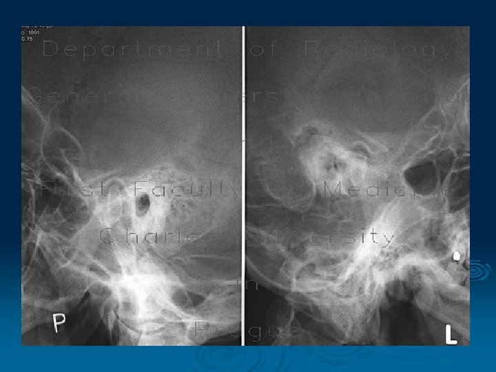
Stenvers Projection § Position with the head rotated 45° toward the opposite side to the side under examination § The central X-ray beam passes between the orbit and external auditory canal 12°caudad § General overview of the petrous bone
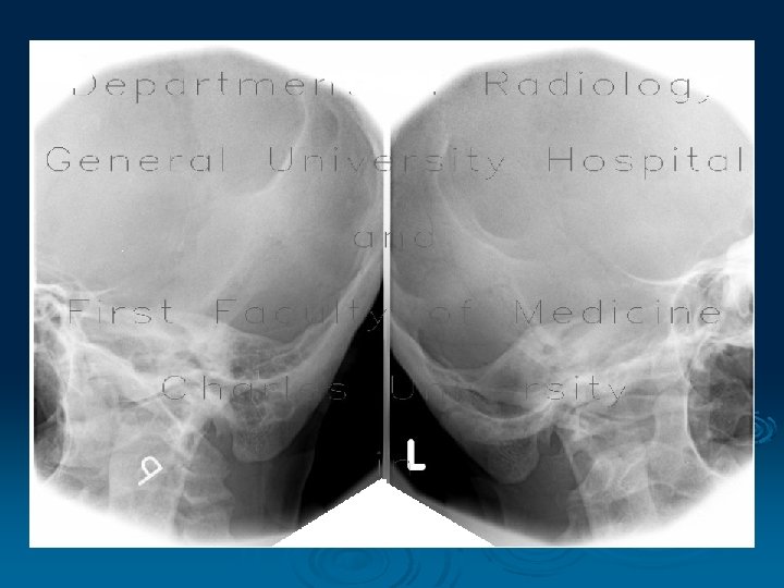
Schuller's Projection § Position with the head turned laterally on the side to be examined § The X-ray tube is angled craniocaudally (about 25°); the central X-ray exits the external auditory canal to be examined view with the mouth closed and opened allows appreciation of the temporomandibular joint dynamics
Albers-Schonberg View Lateral transfacial position - demostrated in open and closed positions (both sides are examined for comparison)
IV. CONTRAST IMAGING § Sialography § Arthrography § Antrography § Cystography § Fistulography § Angiography. . .
Contrast Medium - any substance that is used to enhance the visibility of structures or fluids within the body Negative contrast media - gas - air, CO 2, oxygen (contrast looks less opaque than the surrounding tissue) Positive contrast media - iodine, technecium Double contrast media - iodine + gas
Sialogram with Sjögren's syndrome
Arthrography: single-contrast arthrography - injection of contrast medium double-contrast arthrography - injection of contrast medium and injection of air
V. COMPUTERIZED TOMOGRAPHY § A non-invasive x-ray technique § More sensitive than conventional x-rays § Creating 2 or high-quality 3 dimensional images, scanning in seconds § Abnormal findings can reveal tumors, nodules, cysts, enlarged lymph nodes, and pleural effusions
Osteoma
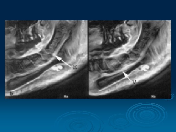
Magnetic Resonance Imaging § MRI allows visualization of soft tissue (muscles, fat, and internal organs) without the use of x-rays § Using two natural, safe forces, magnetic fields and radio waves § Can look “through” hard bones to examine soft tissue
Ultrasonography § A noninvasive procedure § High frequency sound waves are emitted from the transducer and received by the transducer, forming an image that is displayed on the monitor
Thank you for your attention