
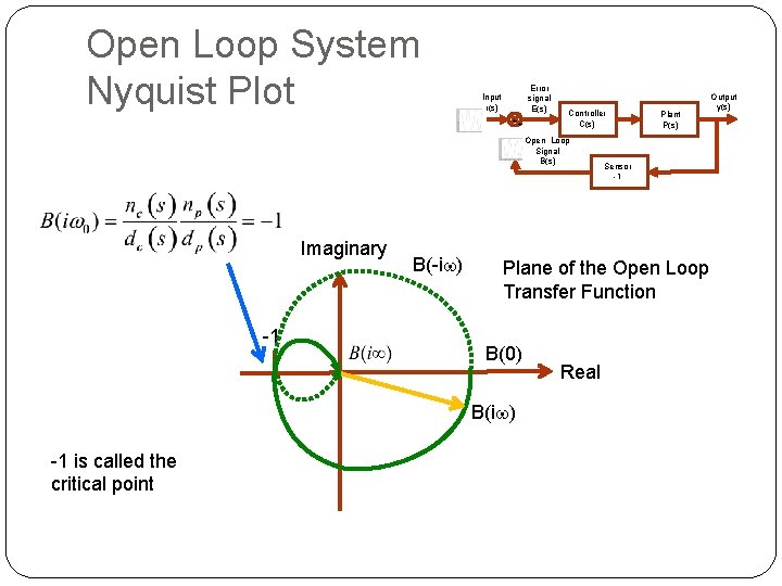
Imaginary 1 is called the 1 critical point
- Slides: 19
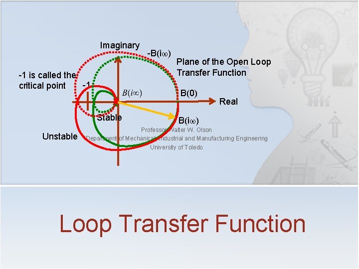
Imaginary -1 is called the -1 critical point Plane of the Open Loop Transfer Function B(0) Stable Unstable -B(iw) Real B(iw) Professor Walter W. Olson Department of Mechanical, Industrial and Manufacturing Engineering University of Toledo Loop Transfer Function
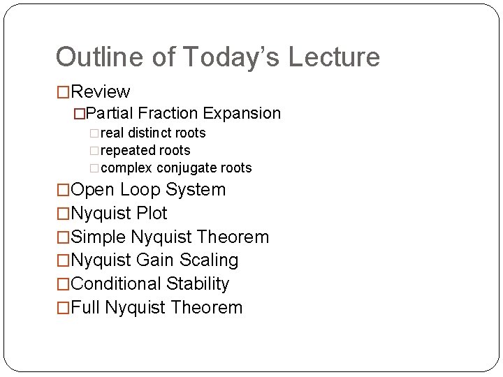
Outline of Today’s Lecture �Review �Partial Fraction Expansion �real distinct roots �repeated roots �complex conjugate roots �Open Loop System �Nyquist Plot �Simple Nyquist Theorem �Nyquist Gain Scaling �Conditional Stability �Full Nyquist Theorem
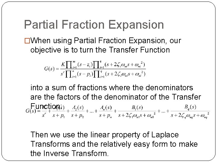
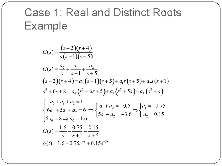
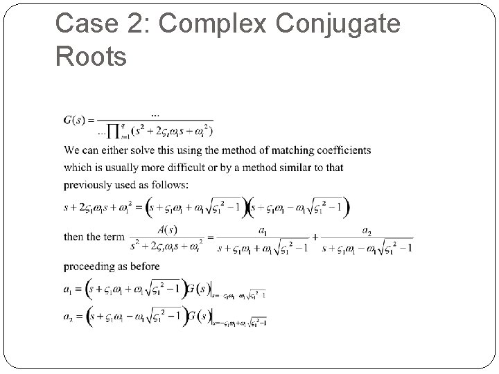
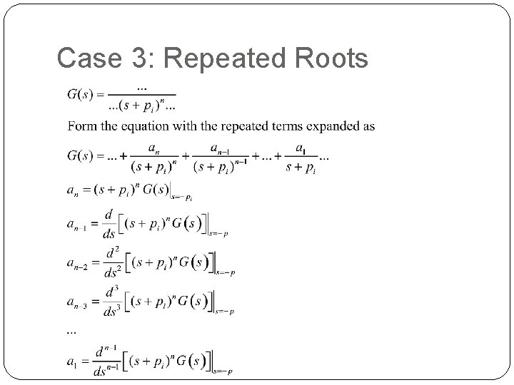
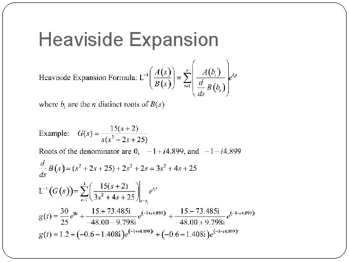
Partial Fraction Expansion �When using Partial Fraction Expansion, our objective is to turn the Transfer Function into a sum of fractions where the denominators are the factors of the denominator of the Transfer Function: Then we use the linear property of Laplace Transforms and the relatively easy form to make the Inverse Transform.
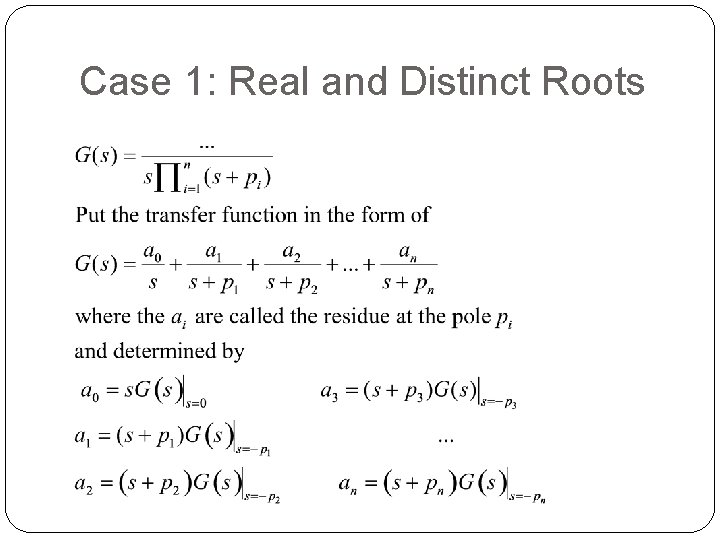
Case 1: Real and Distinct Roots
Case 1: Real and Distinct Roots Example
Case 2: Complex Conjugate Roots
Case 3: Repeated Roots
Heaviside Expansion
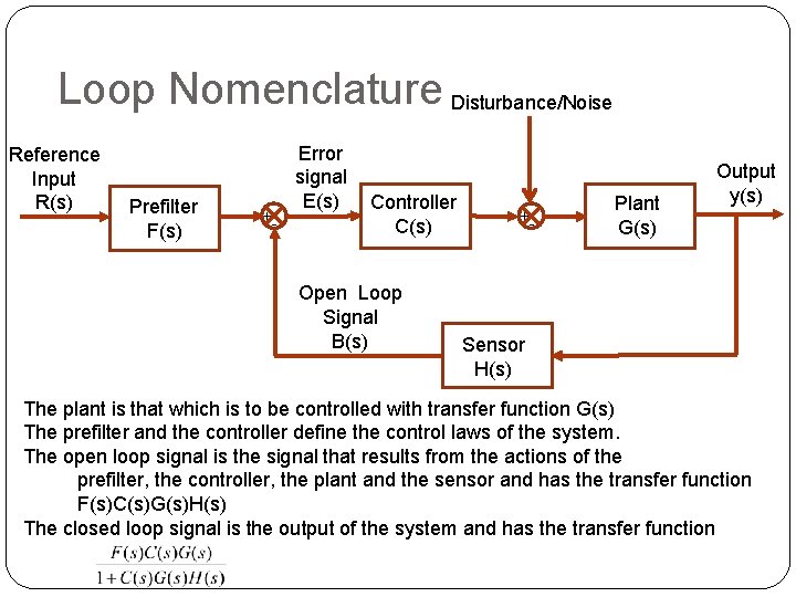
Loop Nomenclature Disturbance/Noise Reference Input R(s) Prefilter F(s) +- Error signal E(s) Controller C(s) Open Loop Signal B(s) +- Plant G(s) Output y(s) Sensor H(s) The plant is that which is to be controlled with transfer function G(s) The prefilter and the controller define the control laws of the system. The open loop signal is the signal that results from the actions of the prefilter, the controller, the plant and the sensor and has the transfer function F(s)C(s)G(s)H(s) The closed loop signal is the output of the system and has the transfer function
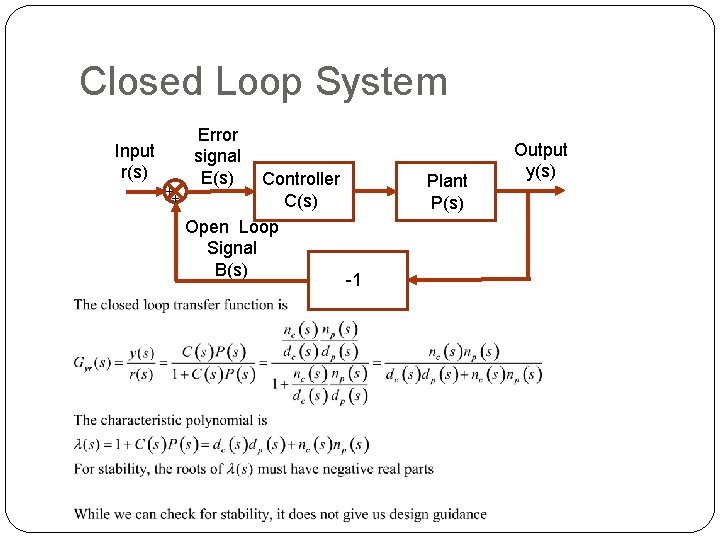
Closed Loop System Input r(s) ++ Error signal E(s) Controller C(s) Open Loop Signal B(s) Plant P(s) -1 Output y(s)
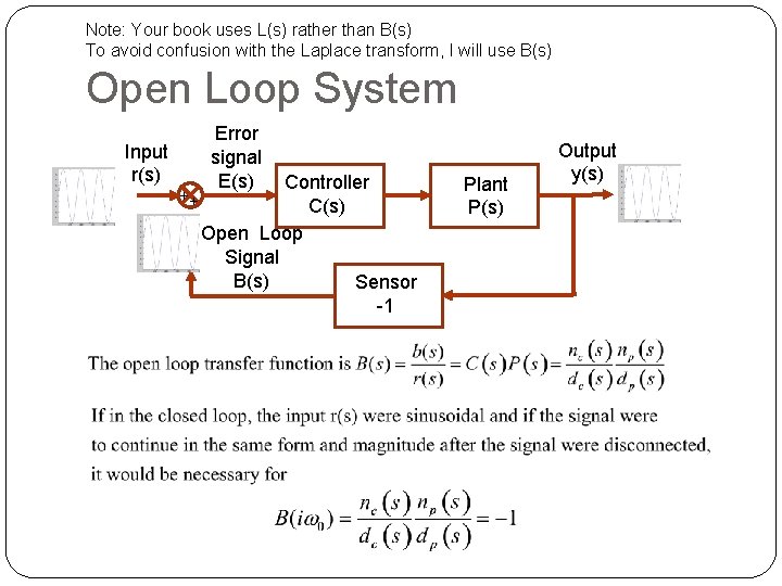
Note: Your book uses L(s) rather than B(s) To avoid confusion with the Laplace transform, I will use B(s) Open Loop System Input r(s) ++ Error signal E(s) Controller C(s) Open Loop Signal B(s) Sensor -1 Plant P(s) Output y(s)
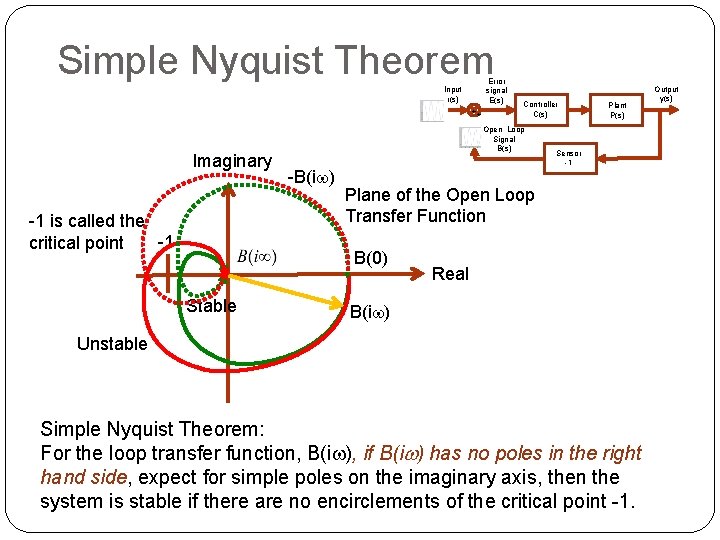
Open Loop System Nyquist Plot Error signal E(s) Input r(s) ++ Controller C(s) Open Loop Signal B(s) Imaginary -1 B(-iw) Sensor -1 Plane of the Open Loop Transfer Function B(0) B(iw) -1 is called the critical point Plant P(s) Real Output y(s)
Simple Nyquist Theorem Error signal E(s) Input r(s) ++ Imaginary -1 is called the -1 critical point Open Loop Signal B(s) -B(iw) Plant P(s) Sensor -1 Plane of the Open Loop Transfer Function B(0) Stable Controller C(s) Real B(iw) Unstable Simple Nyquist Theorem: For the loop transfer function, B(iw), if B(iw) has no poles in the right hand side, expect for simple poles on the imaginary axis, then the system is stable if there are no encirclements of the critical point -1. Output y(s)
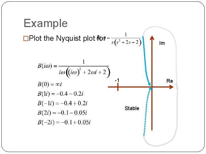
Example �Plot the Nyquist plot for Im -1 Re Stable
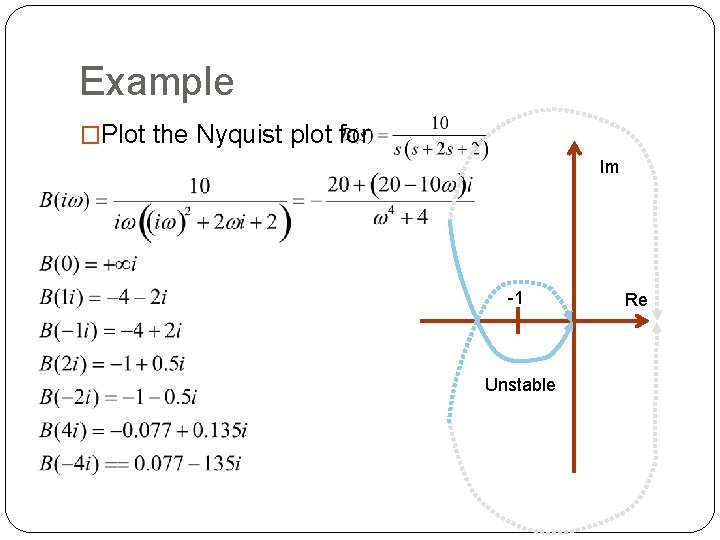
Example �Plot the Nyquist plot for Im -1 Unstable Re
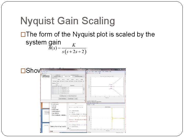
Nyquist Gain Scaling �The form of the Nyquist plot is scaled by the system gain �Show with Sisotool
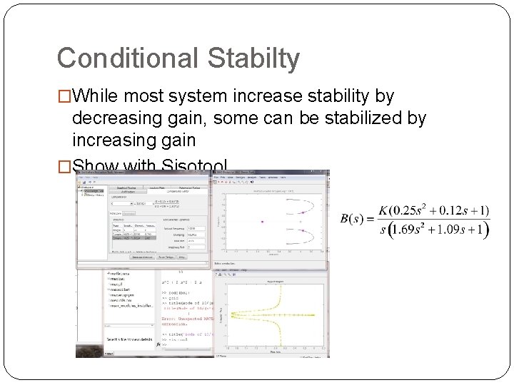
Conditional Stabilty �While most system increase stability by decreasing gain, some can be stabilized by increasing gain �Show with Sisotool
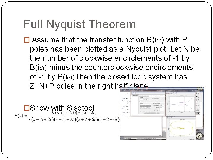
Full Nyquist Theorem � Assume that the transfer function B(iw) with P poles has been plotted as a Nyquist plot. Let N be the number of clockwise encirclements of -1 by B(iw) minus the counterclockwise encirclements of -1 by B(iw)Then the closed loop system has Z=N+P poles in the right half plane. �Show with Sisotool
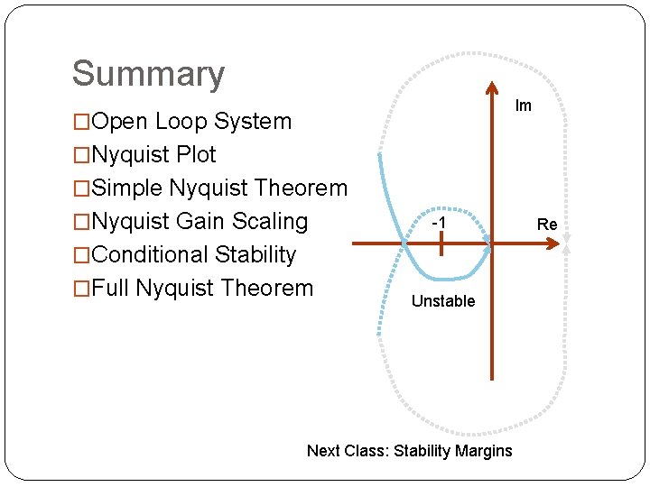
Summary Im �Open Loop System �Nyquist Plot �Simple Nyquist Theorem �Nyquist Gain Scaling -1 �Conditional Stability �Full Nyquist Theorem Unstable Next Class: Stability Margins Re