Image Analysis for Quad Scan and Tomography Quad


- Slides: 13
Image Analysis for Quad Scan and Tomography • Quad scan technique applied successfully to simulation. • Application of technique to experimental data has left questions unanswered. • Beam size measured at YAG 1 significantly different to that suggested by reconstruction (typically >20%). • Previous difficulty in obtaining a real values for the emittance.
Image Analysis for Quad Scan and Tomography Based on experience with simulation data: • space charge model can ensure the fit beam parameters converge towards measured parameters (even in the accelerator model is inaccurate). • good agreement between data and fit at YAG 2 doesn’t mean an accurate reconstruction at YAG 1.
Image Analysis for Quad Scan and Tomography • Application of technique to experimental data has left questions unanswered. Have tried: • improving model. E. g. by including bunch lengthening within model; • different methods for calculating the beam size (bivariate Gaussian fit and direct calculation of second moments).
1. Bunch isn’t necessarily well described by a bivariate Gaussian.
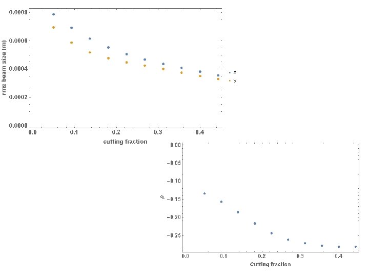
2. For direct calculation of the second moments, measured beam size varies dramatically depending upon whether or not we include the ‘halo’ particles.
Get rid of dimmest pixels until 5% initial intensity is lost: 10% 25% 15% 30%
The selection of cutting fraction for this method is somewhat arbitrary. Cutting same fraction of beam intensity for each YAG image may provide the consistency needed for techniques such as quad scan, however, are we losing relevant information from the tails? Approach 2: halo seen to surround the beam is not actually ‘real’, but is instead a result of scattering within the YAG crystals. For a beam normal to the YAG screen, we should see well resolved central part of the beam, but with blurring at the edges.
The selection of cutting fraction for this method is somewhat arbitrary. Cutting same fraction of beam intensity for each YAG image may provide the consistency needed for techniques such as quad scan, however, are we losing relevant information from the tails? Approach 2: halo seen to surround the beam is not actually ‘real’, but is instead a result of scattering within the YAG crystals. For a beam at 45 o to the YAG screen. Good resolution at proximal side of YAG, smearing out of beam on distal side of YAG.
Good resolution at proximal side of YAG, smearing out of beam on distal side of YAG. Seems consistent with our YAG images…
Can we correct the image? We can try assuming that a plot of single pixel intensities for each row of the YAG image has a Gaussian distribution. For example: fit
We have assumed that each line is described by a Gaussian, but have not made the assumption that the overall distribution is described by a bivariate Gaussian.
Next steps. . • Carry out further modelling to improve understanding of features in YAG image. • Check validity of image correction scheme. • On selection of an appropriate correction scheme, apply quad scan technique to revised beam size measurements.