Illumination and Shading Jehee Lee Seoul National University


 objects yields a uniform illumination •")

 reflects all lights to the direction where angle")


 shading – Each polygon is one face of")


 – You are required")
 – The opaque and translucent polygons should")
 – Submit a report of at most 7")

- Slides: 38
Illumination and Shading Jehee Lee Seoul National University
Photorealism in Computer Graphics • Photorealism in computer graphics involves – Accurate representations of surface properties, and – Good physical descriptions of the lighting effects • Modeling the lighting effects that we see on an object is a complex process, involving principles of both physics and psychology • Physical illumination models involve – Material properties, object position relative to light sources and other objects, the features of the light sources, and so on
Illumination and Rendering • An illumination model in computer graphics – also called a lighting model or a shading model – used to calculate the color of an illuminated position on the surface of an object – Approximations of the physical laws • A surface-rendering method determines the pixel colors for all projected positions in a scene
Light Sources • Point light sources – Emitting radiant energy at a single point – Specified with its position and the color of the emitted light • Infinitely distant light sources – A large light source, such as sun, that is very far from a scene – Little variation in its directional effects – Specified with its color value and a fixed direction for the light rays
Light Sources • Directional light sources – Produces a directional beam of light – Spotlight effects • Area light sources
Light Sources • Radial intensity attenuation – As radiant energy travels, its amplitude is attenuated by the factor – Sometimes, more realistic attenuation effects can be obtained with an inverse quadratic function of distance – The intensity attenuation is not applied to light sources at infinity because all points in the scene are at a nearly equal distance from a far-off source
Light Sources • Angular intensity attenuation – For a directional light, we can attenuate the light intensity angularly as well as radially
Surface Lighting Effects • An illumination model computes the lighting effects for a surface using the various optical properties – Degree of transparency, color reflectance, surface texture • The reflection (phong illumination) model describes the way incident light reflects from an opaque surface – Diffuse, ambient, specular reflections – Simple approximation of actual physical models
Diffuse Reflection • Incident light is scattered with equal intensity in all directions • Such surfaces are called ideal diffuse reflectors (also referred to as Lambertian reflectors)
Diffuse Reflection • Light intensity is independent of angle of reflection • Light intensity depends on angle of incidence
Diffuse Reflection : the intensity of the light source : diffuse reflection coefficient, : the surface normal (unit vector) : the direction of light source, (unit vector)
Ambient Light • Multiple reflection of nearby (light-reflecting) objects yields a uniform illumination • A form of diffuse reflection independent of the viewing direction and the spatial orientation of a surface • Ambient illumination is constant for an object : the incident ambient intensity : ambient reflection coefficient, the proportion reflected away from the surface
Ambient + Diffuse
Specular Reflection • Perfect reflector (mirror) reflects all lights to the direction where angle of reflection is identical to the angle of incidence • It accounts for the highlight • Near total reflector reflects most of light over a range of positions close to the direction
Specular Reflection • Phong specular-reflection model – Note that N, L, and R are coplanar, but V may not be coplanar to the others : intensity of the incident light : color-independent specular coefficient : the gloss of the surface
Specular Reflection • Glossiness of surfaces
Specular Reflection dull glossy
Specular Reflection • Specular-reflection coefficient ks is a material property – For some material, ks varies depending on q – ks =1 if q =90° • Calculating the reflection vector R
Ambient+Diffuse+Specular Reflections • Single light source • Multiple light source • Emission and attenuation
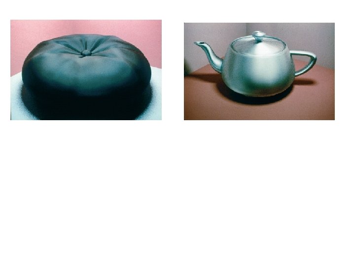
Parameter Choosing Tips • For a RGB color description, each intensity and reflectance specification is a three-element vector • The sum of reflectance coefficients is usually smaller than one • Try n in the range [0, 100] • Use a small ka (~0. 1) • Example – Metal: n=90, ka=0. 1, kd=0. 2, ks=0. 5
Atmospheric Effects • A hazy atmosphere makes colors fade and objects appear dimmer • Hazy-atmosphere effect is often simulated with an exponential attenuation function such as • Higher values for r produce a denser atmosphere
Polygon Rendering Methods • We could use an illumination model to determine the surface intensity at every projected pixel position • Or, we could apply the illumination model to a few selected points and approximate the intensity at the other surface positions • Curved surfaces are often approximated by polygonal surfaces • So, polygonal (piecewise planar) surfaces often need to be rendered as if they are smooth
Constant-Intensity Surface Rendering • Constant (flat) shading – Each polygon is one face of a polyhedron and is not a section of a curved-surface approximation mesh
Intensity-Interpolation Surface Rendering • Gouraud shading – Rendering a curved surface that is approximated with a polygon mesh – Interpolate intensities at polygon vertices • Procedure 1. Determine the average unit normal vector at each vertex 2. Apply an illumination model at each polygon vertex to obtain the light intensity at that position 3. Linearly interpolate the vertex intensities over the projected area of the polygon
Intensity-Interpolation Surface Rendering • Normal vectors at vertices – Averaging the normal vectors for each polygon sharing that vertex ( N 1 + N 2 + N 3 + N 4 ) Nv = N 1 + N 2 + N 3 + N 4
Intensity-Interpolation Surface Rendering • Intensity interpolation along scan lines – I 4 and I 5 are interpolated along y-axis, and then – Ip is interpolated along x-axis • Incremental calculation is also possible y 3 1 scan line p 4 5 2 x
Intensity-Interpolation Surface Rendering
Gouraud Shading Problems • Lighting in the polygon interior is inaccurate • Mach band effect – Optical illusion
Mach Band Effect • These “Mach Bands” are not physically there. Instead, they are illusions due to excitation and inhibition in our neural processing The bright bands at 45 degrees (and 135 degrees) are illusory. The intensity of each square is the same.
Normal-Vector Interpolation Surface Rendering • Phong shading – Interpolate normal vectors at polygon vertices • Procedure 1. Determine the average unit normal vector at each vertex 2. Linearly interpolate the vertex normals over the projected area of the polygon 3. Apply an illumination model at positions along scan lines to calculate pixel intensities n 1 n 2 n 3
Gouraud versus Phong Shading • Gouraud shading is faster than Phong shading – Open. GL supports Gouraud shading • Phong shading is more accurate
Problems with Interpolated Shading • • Polygon silhouette Perspective distortion Orientation dependence Shared edges
Programming Assignment #4 • Shading opaque and translucent surfaces (20%) – You are required to render two overlapping surfaces • The sweep polygonal surface from the previous assignment should be opaque and shaded smoothly • A translucent cube (or any simple object) should be created and placed such that it intersects the opaque sweep surface • Material (20%) – Use at least five different material in the scene – Select material properties for the surfaces, such as metal, plastic, rubber, and so on.
Programming Assignment #4 • Depth ordering (20%) – The opaque and translucent polygons should be sorted in a depth order such that they can be rendered appropriately – It is important to render translucent polygons properly when they intersect opaque polygons • Viewing and Lighting (20%) – Use more than three light sources to illuminate the surfaces appropriately when they are viewed from an arbitrary viewpoint – The user should be able to change the viewpoint
Programming Assignment #4 • Report (20%) – Submit a report of at most 7 pages – Explain material properties of each surface • What material do you want to simulate? • Describe all coefficients of the illumination model – Explain your depth ordering algorithm briefly • How do you handle intersecting polygons? – Explain the lighting configuration • How many light sources do you use? • Where do you put the light sources? • What is the type of each light source?
Programming Assignment #4 • Optional requirements – You may render complex opaque and translucent objects – You may implement BSP trees for depth ordering