ILC International Linear Collider DR e lineac e


")


 300 Hz conventional 陽電子源")


 no stacking")


 the same")


")
")


 • 2 possible schemes")


 Both in the tunnel 300 Hz conventional e+ source undulator")


 73")


 – high current – high rep rate")

 –")


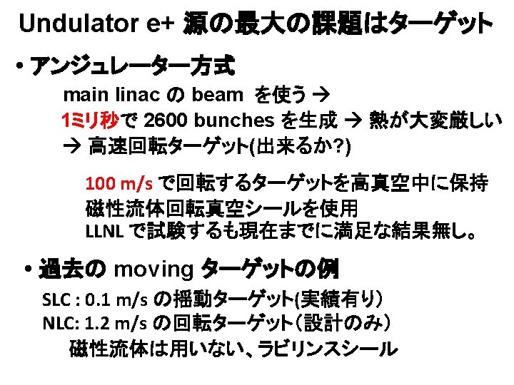
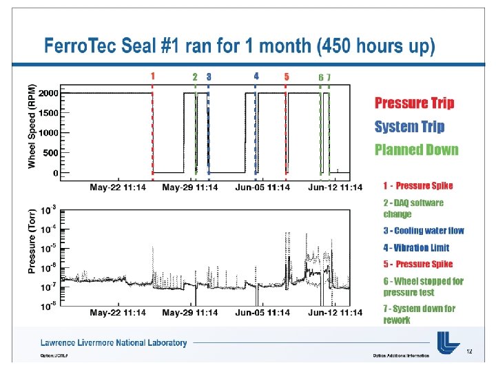
 • 真空中で 100 m/sで動く 標的が必要 • LLNLで 2社からの Ferromagnet sealをつ かって試験中 •")
 88")
 If we start with \"Conventional\", we need to keep smooth path to")
 If we start with \"Conventional\", we need to keep smooth path to")
 If we start with \"Conventional\", we need to keep smooth path to")


- Slides: 96
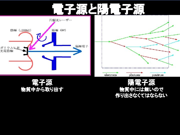
ILC: International Linear Collider DR e- lineac e - 源 e+ lineac 31 ~ 50 km e+ 源 Ecm = 500 - 1000 Ge. V DR
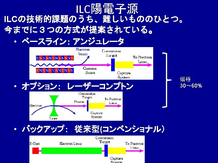
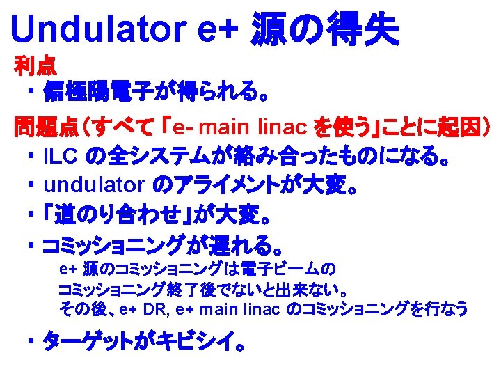
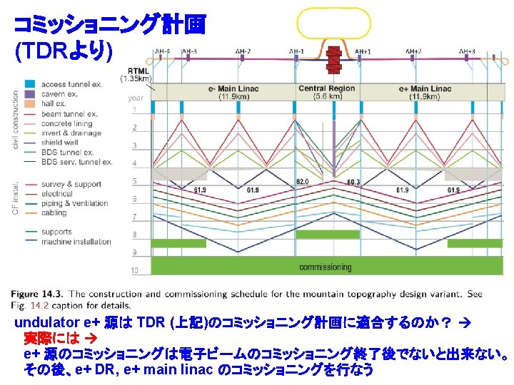
ILC baseline 陽電子源 (undulator 陽電子源)
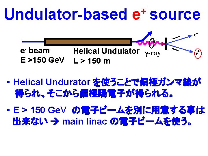
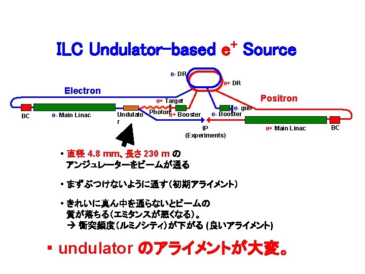
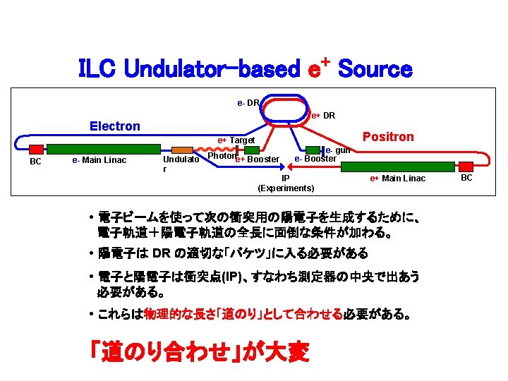
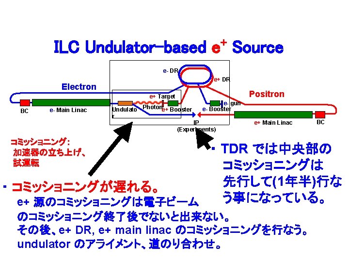
ILC Undulator-based e+ Source e- DR e+ DR Electron Positron e+ Target BC e- Main Linac Undulato Photone+ Booster r e- gun e- Booster IP (Experiments) e+ Main Linac BC
Undulator Cryomodule U Beam Heat Shield Helical Undulator He Vessel 06/27/14 12
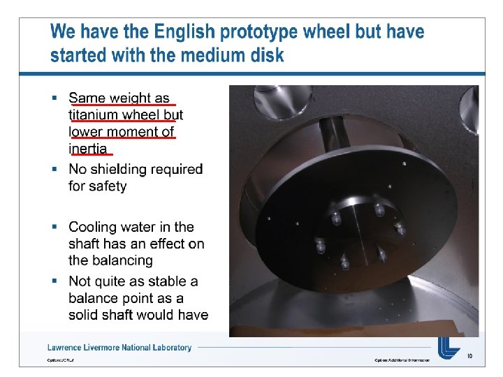
Positron Generation • 15 mm Ti-alloy. • 100 m/s tangential speed. 2013年 In good vacuum. • There is no room for Same speed as E 6 wheel in vacuum ! optimization (pulse structure is fixed). • Thechnical design of the water joint and vacuum seal. 11/05/12 2013ILC夏の合宿(富山) 13
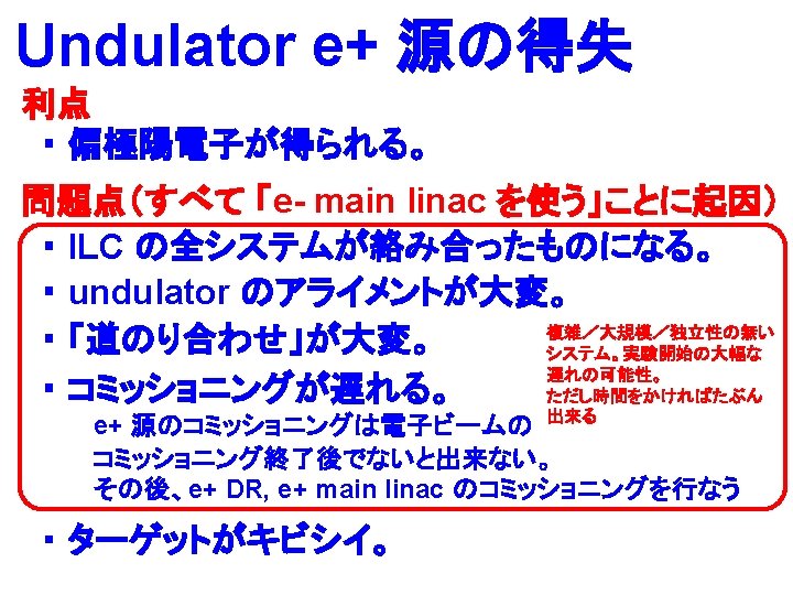
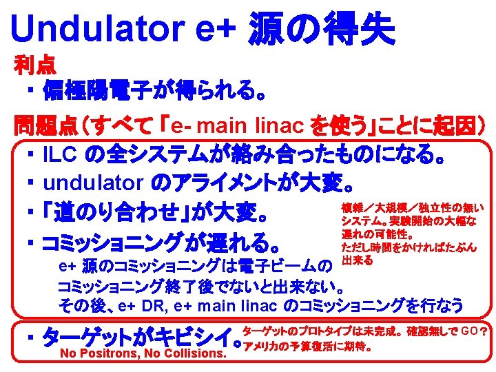
ILC Undulator-based e+ Source e- DR e+ DR Electron Positron e+ Target BC e- Main Linac Undulato Photone+ Booster r e- gun e- Booster IP (Experiments) e+ Main Linac ILC の全システムが絡み合っている BC
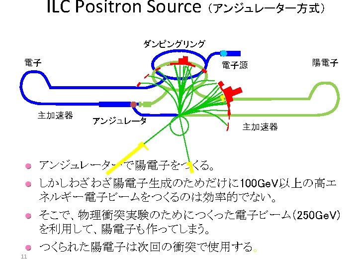
ILC Undulator-based e+ Source e- DR e+ DR Electron Positron e+ Target BC e- Main Linac Undulato Photone+ Booster r e- gun e- Booster IP (Experiments) e+ Main Linac • e+ 生成用ターゲットは main linac のビーム持続時間 (1 m sec) の間に 2600 バンチ (1バンチ = 2 x 10¹⁰ ヶ)の e+ を作らなければ ならない。 ターゲットが熱的に非常にキビシイ。 100 m/s で動くターゲットが必要。 BC
ECFA LC 2013 での Jeff Gronberg 氏のスライドより
ECFA LC 2013 での Jeff Gronberg 氏のスライドより
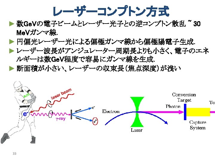
別の方法 (2) 300 Hz conventional 陽電子源
300 Hz scheme e+ generation in 63 m sec (cf. undulator : in 1 m sec) Truly Conventional Collaboration ANL, IHEP, Hiroshima U, U of Tokyo, KEK, DESY, U of Hamburg NIM A 672 (2012) 52— 56
How? • Total Number of bunches: 2640 • Divide into 20 triplets (1 Triplet = 3 Mini-Trains) • Each triplet contains 132 bunches • 2640 = 20 x 132 • 300 Hz creation of triplets triplet to triplet time space = 3. 3 m sec • Create 20 triplets : 63 m sec Stretching in time
Conventional e+ Source for ILC Normal Conducting Drive and Booster Linacs in 300 Hz operation e+ creation go to main linac 20 triplets, rep. = 300 Hz • triplet = 3 mini-trains with gaps • 44 bunches/mini-train, Tb_to_b = 6. 15 n sec Drive Linac Several Ge. V NC 300 Hz 2640 bunches/train, rep. = 5 Hz • Tb_to_b = 369 n sec Booster Linac 5 Ge. V NC 300 Hz Target Amorphous Tungsten Pendulum or Slow Rotation DR Tb_to_b = 6. 15 n sec 2640 bunches 60 mini-trains Time remaining for damping = 137 m sec We create 2640 bunches in 63 m sec
Conventional e+ Source for ILC Normal Conducting Drive and Booster Linacs in 300 Hz operation e+ creation go to main linac 20 triplets, rep. = 300 Hz • triplet = 3 mini-trains with gaps • 44 bunches/mini-train, Tb_to_b = 6. 15 n sec Drive Linac Several Ge. V NC 300 Hz 2640 bunches/train, rep. = 5 Hz • Tb_to_b = 369 n sec Booster Linac 5 Ge. V NC 300 Hz Target Amorphous Tungsten Pendulum or Slow Rotation DR Tb_to_b = 6. 15 n sec 2640 bunches 60 mini-trains Time remaining for damping = 137 m sec We create 2640 bunches in 63 m sec Stretching
Beam before DR =132 bunches <-- the 100 ns gap is required to cure an e- cloud problem in e+ DR.
Beam before DR =132 bunches Injection: usual kicker ( ~ 1 us) no stacking is necessary <-- the 100 ns gap is required to cure an e- cloud problem in e+ DR.
Conventional e+ Source for ILC Normal Conducting Drive and Booster Linacs in 300 Hz operation e+ creation go to main linac 20 triplets, rep. = 300 Hz • triplet = 3 mini-trains with gaps • 44 bunches/mini-train, Tb_to_b = 6. 15 n sec Drive Linac Several Ge. V NC 300 Hz 2640 bunches/train, rep. = 5 Hz • Tb_to_b = 369 n sec Booster Linac 5 Ge. V NC 300 Hz Target Amorphous Tungsten Pendulum or Slow Rotation DR Tb_to_b = 6. 15 n sec 2640 bunches 60 mini-trains Time remaining for damping = 137 m sec We create 2640 bunches in 63 m sec
Beam after DR
Beam after DR Extraction: fast kicker ( 3 ns kicker: Naito kicker) the same as the baseline
Target and Drive_Beam Optimization
Parameter Plots for 300 Hz scheme e- directly on to Tungsten colored band s=4. 0 mm Ne-(drive) = 2 x 10¹⁰ /bunch 1 2 3 4 accepted e+/e. PEDD J/g d. T max by a triplet 5 35 J/g 500 k 100 k there seems to be solutions
Target Heat Simulation (Wanming)
Target Heat Simulation assumption: 5 m/s undulator 源の 1/20 (Wanming)
R/D items
R&R Issues of the Conventional Source • “conventional” but still needs some more R&D • High current, high rep rate driver linac • Moving target • Flux concentrator • Booster linac • Overall simulation 2013/8/30 ILC monthly, Yokoya 50
Moving Target • ~5 m/sec required (1/20 of undulator scheme) • 2 possible schemes being developed at KEK 5 Hz pendulum with bellows seal air bellows seal rotating target with ferromagnetic seal ferromagnetic fluid seal vacuum air main issue: life of bellows vacuum main issue: vacuum First step prototype fabricated 2013/8/30 ILC monthly, Yokoya 51
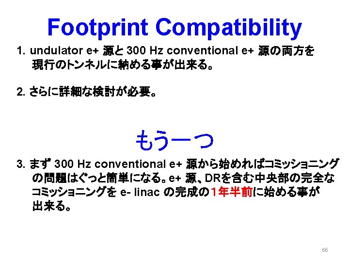
どのように議論を進めて コンセンサスを作って行くか Undulator-Conventional Footprint Compatibility 53
Nick's Suggestion@ADI-CFS(Tokyo, April 2014) Both in the tunnel 300 Hz conventional e+ source undulator e+ source
ILC Undulator-based e+ Source e- DR e+ DR Electron Positron e+ Target BC e- Main Linac Undulato Photone+ Booster r e- gun e- Booster IP (Experiments) ココをよく見てみよう e+ Main Linac BC
Central Region Tunnel 4. 50 meters Service Tunnel 6. 75 meters 8. 00 meters Beam Tunnel 完全なツイン・トンネルになっている The Tunnel is Wide.
Undulator Source in Central Region Tunnel PSs muon wall EFADL EUPM D EUND AUX PCAP PPA UPT Ds EDOGL EPUNDDL 3. 3 3. 1 PSs 2. 9 2. 7 • PTAPA 2. 5 PTRAN BDS PBSTR D 2. 3 2. 1 1. 9 1. 7 1. 5 Distance from IP (km) EUPM Electron Undulator Protection and Matching EUND Electron Undulator Section EFADL Electron Fast Abort Line UPT Undulator Photon Transport to Target PTAPA Positron Source Target Area and Pre-Accelelator EDOGL Electron Dogleg EPUNDL Electron Post-Undulator Dump Line PTRANH 1. 3 1. 1 0. 9 0. 7 0. 5 PCAP Positron Source Capture Section PPA Positron Source Pre-Accelerator PTRAN Positron Source Transfer Line PBSTR Positron Source 5 Ge. V Booster PTRANH Positron Source Transfer Line (High Energy) AUX Auxilliary Source ref. G-05, G-06, U-04, U-05, U-06, U-07, U-08, U-09, U-10, U-11
Undulator Source in Central Region Tunnel PSs muon wall EFADL EUPM D EUND AUX PCAP PPA UPT Ds EDOGL EPUNDDL 3. 3 3. 1 PSs 2. 9 2. 7 • PTAPA 2. 5 PTRAN BDS PBSTR PTRANH D 2. 3 2. 1 1. 9 1. 7 1. 5 Distance from IP (km) 1. 3 1. 1 0. 9 0. 7 0. 5 The Undulator Source is Long. EUPM Electron Undulator Protection and Matching EUND Electron Undulator Section EFADL Electron Fast Abort Line UPT Undulator Photon Transport to Target PTAPA Positron Source Target Area and Pre-Accelelator EDOGL Electron Dogleg EPUNDL Electron Post-Undulator Dump Line PCAP Positron Source Capture Section PPA Positron Source Pre-Accelerator PTRAN Positron Source Transfer Line PBSTR Positron Source 5 Ge. V Booster PTRANH Positron Source Transfer Line (High Energy) AUX Auxilliary Source ref. G-05, G-06, U-04, U-05, U-06, U-07, U-08, U-09, U-10, U-11
Undulator Source in Central Region Tunnel • 3. 3 3. 1 2. 9 2. 7 2. 5 2. 3 2. 1 1. 9 1. 7 1. 5 Distance from IP (km) Busy Areas 1. 3 1. 1 0. 9 0. 7 0. 5
Undulator Source in Central Region Tunnel • 3. 3 3. 1 2. 9 2. 7 2. 5 2. 3 2. 1 1. 9 1. 7 1. 5 Distance from IP (km) 1. 3 Busy Areas Not Busy 1. 1 0. 9 0. 7 0. 5
Undulator Source in Central Region Tunnel 479 m ~ 450 m ~ 430 m • 3. 3 3. 1 2. 9 2. 7 2. 5 2. 3 2. 1 1. 9 1. 7 1. 5 Distance from IP (km) 1. 3 Busy Areas Not Busy 1. 1 0. 9 0. 7 0. 5
Use Not-Busy Areas 479 m ~ 450 m ~ 430 m • 3. 3 3. 1 2. 9 2. 7 2. 5 2. 3 2. 1 1. 9 1. 7 1. 5 Distance from IP (km) 1. 3 1. 1 0. 9 0. 7 0. 5
Conventional Source in Central Region Tunnel PSs PSs CPTAPA CPDEL CPDET CPCAP CPBSTR D • 3. 3 3. 1 2. 9 2. 7 2. 5 2. 3 2. 1 1. 9 1. 7 1. 5 Distance from IP (km) 1. 3 CPTRANH CPPA 1. 1 0. 9 0. 7 0. 5 CPDEL Conventional Positron Source Drive Electron Linac CPTAPA Positron Source Target Area and Pre-Accelelator CPCAP Conventional Positron Source Capture Section CPPA Conventional Positron Source Pre-Accelerator CPDET Conventional Positron Source Drive Electron Transfer Line CPBSTR Conventional Positron Source 5 Ge. V Booster CPTRANH Conventional Positron Source Transfer Line (High Energy)
Both Sources in Central Region Tunnel Conventional Source • Undulator Source 3. 3 3. 1 2. 9 2. 7 2. 5 2. 3 2. 1 1. 9 1. 7 1. 5 Distance from IP (km) 1. 3 1. 1 Footprint Compatibility Both Sources in TDR Tunnel 0. 9 0. 7 0. 5
Backup Slides
Helical Undulator 11/05/12 2013ILC夏の合宿(富山) 73
Positron Generation • 15 mm Ti-alloy. • 100 m/s tangential speed. 2013年 In good vacuum. • There is no room for Same speed as E 6 wheel in vacuum ! optimization (pulse structure is fixed). • Thechnical design of the water joint and vacuum seal. Ferrofluid 11/05/12 2013ILC夏の合宿(富山) 74
In the case of 300 Hz scheme spacing between triplets =3. 3 ms 132 bunches in 992 ns good for a FC we can use existing FC technology
Assumptions 132 bunches make a shock wave heat same position on the target drive electrons 2× 10¹⁰/bunch a triplet: 132 bunches 992 ns each triplet hits different position on the target 3. 3 ms a train: 20 triplet = 2640 bunches 63 ms pendulum or slow rotation target
Flux Concentrator • Almost existing technology – pulse length ~1 msec (cf. ~1 msec in undulator scheme) • Beam aperture should be a bit larger – ~7 mm ~12 mm • Being developed for Super. KEKB – It has 14 mm aperture 2013/8/30 ILC monthly, Yokoya 79
Linacs • Driver linac (~6 Ge. V) – high current – high rep rate (300 Hz) • Booster linac (~5 Ge. V) – high rep rate – accurate loading compensation (due to uneven bunch structure) 2013/8/30 ILC monthly, Yokoya 2× 10¹⁰/bunch a triplet: 132 bunches 992 ns 3. 3 ms a train: 20 triplet = 2640 bunches 63 ms 80
Loading Compensation Scheme Urakawa 3 x 10¹⁰ positron/bunch 300 Hz triplet beam Less than +/- 0. 7% 200 MW, 3 ms 300 Hz Power Supply 80 MW Klystron Low Level RF Phase Shifter and Amp. 3 d. B High Power RF Combiner 50 W High Power Terminator precise control of the phase shifters needed 3 m long constant gradient travelling wave structure Test at ATF linac being planned 2013/8/30 ILC monthly, Yokoya 81
Overall Simulation • DR aperture Longitudinal Phase Space • Must include Pz(Me. V) – DE < +-37. 5 Me. V – Dz < +-34 mm – Ax+Ay < 70 mm – target simulation – loading compensation • Is S-band linac acceptable? 2013/8/30 ILC monthly, Yokoya +- 3. 46 cm Time (ns) 82
Dependence on Drive beam size , Ne-/bunch = 2 x 10¹⁰ e+/e- =1. 5 35 J/g s of the Drive e- Beam (mm)
Conventional e+ Source for ILC Normal Conducting Drive and Booster Linacs in 300 Hz operation e+ creation go to main linac 20 triplets, rep. = 300 Hz • triplet = 3 mini-trains with gaps • 44 bunches/mini-train, Tb_to_b = 6. 15 n sec Drive Linac Several Ge. V NC 300 Hz 2640 bunches/train, rep. = 5 Hz • Tb_to_b = 369 n sec Booster Linac 5 Ge. V NC 300 Hz Target Amorphous Tungsten Pendulum or Slow Rotation Truly Conventional * We assume single solid target. DR Tb_to_b = 6. 15 n sec 2640 bunches 60 mini-trains * NO Liquid Target or Time remaining for damping = 137 m sec NO Hybrid Target are assumed
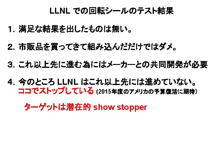
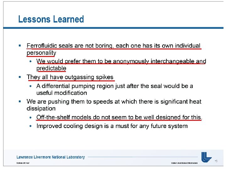
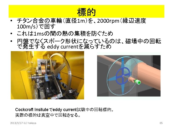
標的 (2) • 真空中で 100 m/sで動く 標的が必要 • LLNLで 2社からの Ferromagnet sealをつ かって試験中 • 十分な成果は上がって いない – Outgassing spikes still being observed • More works needed – market products don’t work 2013/9/17 ILC Yokoya 86
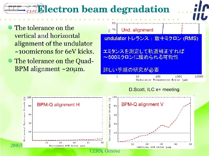
Effects on the electron beam W. Liu, PAC 09 11/05/12 2013ILC夏の合宿(富山) 88
Discussion@LCWS 2013(Tokyo) If we start with "Conventional", we need to keep smooth path to "Undulator". footprint compatibility (no change of the tunnel) • "300 Hz conventional source" should fit the space for "undulator source" 1 st step 300 Hz conventional e+ source
Discussion@LCWS 2013(Tokyo) If we start with "Conventional", we need to keep smooth path to "Undulator". footprint compatibility (no change of the tunnel) • "300 Hz conventional source" should fit the space for "undulator source" Remove the Conventional Source
Discussion@LCWS 2013(Tokyo) If we start with "Conventional", we need to keep smooth path to "Undulator". footprint compatibility (no change of the tunnel) • "300 Hz conventional source" should fit the space for "undulator source" 2 nd step undulator e+ source
Central Region Tunnel 4. 50 meters Service Tunnel 6. 75 meters 8. 00 meters Beam Tunnel
Undulator Source in Central Region Tunnel • 3. 3 3. 1 2. 9 2. 7 2. 5 2. 3 2. 1 1. 9 1. 7 1. 5 Distance from IP (km) 1. 3 1. 1 0. 9 0. 7 0. 5
Conventional Source in Central Region Tunnel • 3. 3 3. 1 2. 9 2. 7 2. 5 2. 3 2. 1 1. 9 1. 7 1. 5 Distance from IP (km) 1. 3 1. 1 0. 9 0. 7 0. 5
Undulator Source in Central Region Tunnel • 3. 3 3. 1 2. 9 2. 7 2. 5 2. 3 2. 1 1. 9 1. 7 1. 5 Distance from IP (km) 1. 3 1. 1 0. 9 The Undulator Source is Long. 0. 7 0. 5
Parameter Plots for 300 Hz scheme e- directly on to Tungsten colored band s=4. 0 mm Ne-(drive) = 2 x 10¹⁰ /bunch 1 2 3 4 accepted e+/e. PEDD J/g d. T max by a triplet 5 35 J/g 500 k 100 k