IHEP 1 3 GHz horizontal Cryomodule and vertical


- Slides: 28
IHEP 1. 3 GHz horizontal Cryomodule and vertical test Dewar IHEP Cryogenic group The Third IHEP-KEK 1. 3 GHz SC Technology Collaboration Meeting Dec. 7 -8, 2010, IHEP, Beijing
Outline • Horizontal Cryomodule Progress Structure design • Vertical test Dewar Progress Structure design Key parts research
Horizontal Cryomodule
Horizontal cryomodule progress • Structure determined in Feb. 2010 • 1 st version cryostat drawings finished in May. 2010 (without detailed size of cavity, input coupler, tuner etc) • Interface determined in Oct. 2010 • 1 st version cryomodule drawings will be finished in two month • ……
Horizontal cryomodule flow chart Here just the roughly flow chart of horizontal test cryomodule , The complete PID diagram will be done after the project of the cryogenic system is determined.
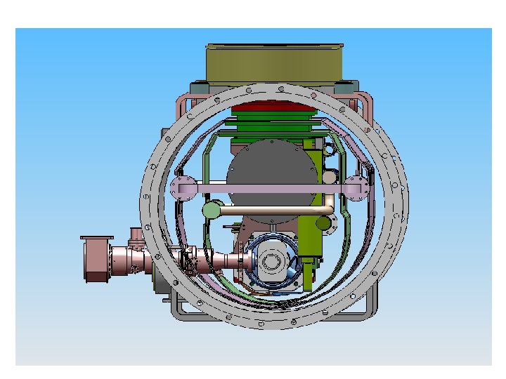
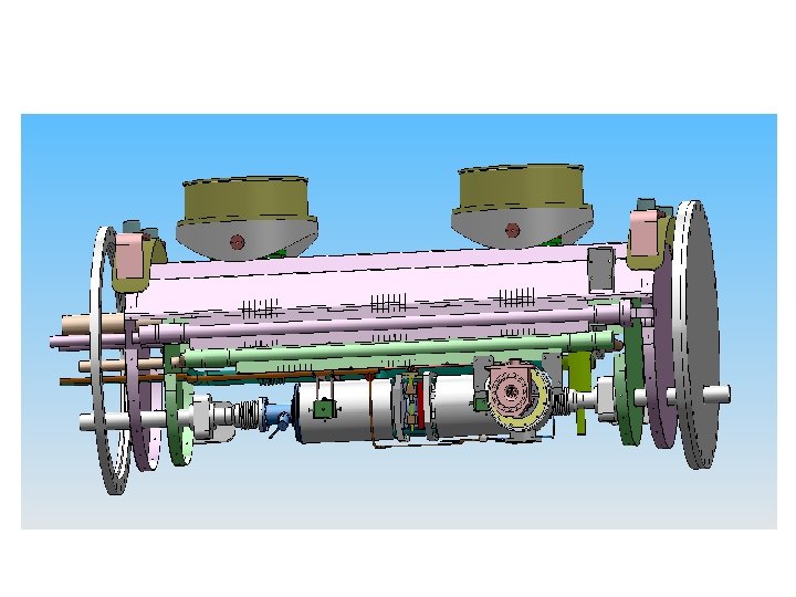
Structure design-3 D drawings
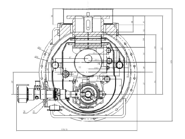
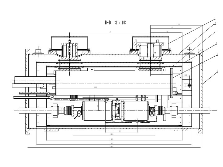
Structure design-general assembly drawings Total length 2733 mm Height 2157 mm From base line to cavity center 1200 mm Vacuum vessel size Ø 966× 10
Interface coordinate Discussed in Oct 27 th. 2010 by J. Y. Zhai
Interface coordinate Based on these interface coordinates, the completely cryomodule drawings are in process.
Vertical test Dewar
Vertical test Dewar progress • Structure design with reference of Fermilab’s vertical test Dewar • 1 st version drawings have been finished in Oct. 2010 (without heat exchanger, magnetic shielding) • Heat exchanger has been designed in Nov. 2010 • Magnetic shielding is under research • 1 st completely Vertical test Dewar drawings will be finished in two month • ……
Vertical test Dewar flow chart Like horizontal test cryomodule, the complete PID diagram of vertical test Dewar also will be done after the project of the cryogenic system is determined.
Vertical Test Dewar FNAL vertical test cryostat
IHEP Vertical Test Dewar
Assembly drawings Total height 4978 mm Inner height 4464 mm Inner diameter 668 mm
Top flange
Phase separator
Heat exchanger
Finned tube Total length nearly 6 m
Magnetic shielding • Fermilab use two-layer cylindrical magnetic shielding Room temperature outer shield outside the vacuum vessel: 1 mm Amumetal Inner shield inside the helium vessel: 1 mm Cryoperm (Magnetic conductance can be increased 10 times from 78 K to 4. 2 K) from Germany VAC company
IHEP experience in magnetic shielding (Magnetic Shield for the Vertical Test System of Superconducting Cavity HIGH ENERGY PHYSICS AND NUCLEAR PHYSICS 0 ct.2005 SUN Hong etc. ) Vertical test Dewar for 1. 3 GHz single cell cavity: two layers inside the helium vessel Test result at room temperature : Axial residual magnetic field<140 n. T (1. 4 m. Gs) Radial residual magnetic field <40 n. T(0. 4 m. Gs) BEPCⅡ spare cavity vertical test Dewar: one layer outside the vacuum vessel Test result: residual magnetic field (20~40 m. Gs)
1. 3 GHz vertical test Dewar magnetic shielding • Keep on the experiment to test these materials’ performance at 300 K, 78 K, 4. 2 K, and this work has been under plan; • Investigate the material Cryoperm further, we have contacted with Germany vacuumschmelze(VAC) company and waiting for the detailed information.
Next step…… • Finish the completely 1 st version drawings of the horizontal cryomodule, and then do the joint checking so that the last drawings can be realized earlier. • manufacture and test of the heat exchanger as soon as possible. • Finish the magnetic shielding materials’ performance test, and then determine the last magnetic shielding material(s). • Finish the last version drawings of vertical test Dewar, and hopefully it can be put it into machining in the first half of next year. • ……
Thanks