IHCE Source of LowEnergy HighCurrent Electron Beams LEHCEB
 Common view of the installation. 1")
IHCE Source of Low-Energy High-Current Electron Beams (LEHCEB) Common view of the installation. 1 – vacuum chamber; 2 – HV gate valve; 3 – turbo drag pump TMU 521; 4 – rotary pump DU 20; 5 – valves VAP 025; 6 - oil mist filter ONF 25 l and condensate separator KAS 25 l; 7 – compact full-range gauge PKR 25 l; 8 – massspectrometer of residual gases MX 7304; 9 – e-gun; 10 – high voltage pulse generator; 11 – power supplies and control units of e-gun; 12 – pure argon balloon. ВТ 10 Electron Beam Authograph 2 4
 5. 3 k. V/div), diode")
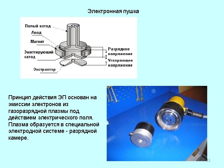
IHCE LEHCEB Source Time-phased waveforms of accelerating voltage (1) 5. 3 k. V/div), diode current (2) 14. 4 k. A/div), beam current (3) 5 k. A/div) Beam parameters 1 – cathode 2 – cathode plasma 3 – double electric layer 4 – anode plasma 5 – collector 6 – solenoid 7 – body of e-beam gun 8 – operating chamber • electron energy 10 to 40 ke. V • peak electron current up to 30 k. A • beam pulse duration 2 to 5 S • beam energy density per pulse 1 -40 J/cm 2 • beam cross section up to 50 cm 2 • pulse repetition rate up to 0. 2 Hz 3 5

IHCE Computer-controlled Pulsed e-beam Machine for Surface Treatment Beam parameters • electron energy 5 to 25 ke. V • peak electron current 20 to 250 A • beam pulse duration 50 to 200 S • beam energy density per pulse 1 to 70 J/cm 2 • spot diameter 2 to 5 cm • pulse repetition rate 0. 3 to 20 Hz 4 6

Block diagram of pulsed e-beam Machine 5 7

Schematic of CRS® system Cathode 20 -30 k. V, 5 -25 k. A, 2 -4 ms 7 5 8 Anode for plasma discharge 4 -5 k. V, 50 -200 A, 30 ms 4 6 Solenoid 1 -2 k. V, 100 -200 A, 10 ms 1 1. Vacuum chamber, 9 2. Fore vacuum pump 3. Turbo molecular pump / diffusion pump 4. Argon gas cylinder, 5. Solenoid 3 2 6. Anode ring for plasma discharge 7. Cathode wire, 8. Anode plasma, 9. Carbon sample Fig. 1 Schematic illustration of EB system CRS with Explosive Electron Emission ( EEE) method 6
 Professors Grigoriev and T. Koval (b) (c) Electron beam self-focusing control")
Electron Transport (a) Professors Grigoriev and T. Koval (b) (c) Electron beam self-focusing control in breakdown plasma by external magnetic field 77

Treatment of non conducting ceramics by electron beam and by ion beam Efim Oks Tomsk, Russia High Current Electronics Institute, Russian Academy of Sciences and State University of Control Systems and Radioelectronics 14

Fore-vacuum plasma cathode electron source 1 Id 7 U 5 1 - hollow cathode, 2 - anode, 3 - accelerating electrode, 4 4 - emission grid, 2 Ie 6 3 Ue 5, 6 - insulators, 7 – plasma, 8 - electron beam 8 Ib 15

Plasma electron gun for operation at fore-pump pressure range hollow cathode Beam current – up to 0, 3 A dc Beam energy – up to 20 ke. V Beam power – up to 6 k. W plasma anode Beam diameter – 3 ÷ 5 mm Working gas – residual electron beam accelerating atmosphere, Ar, He electrode Gas pressure - 1 ÷ 15 Pa 16

Fore-pump plasma cathode electron gun 17

Installation for testing fore-pump plasma electron gun 18

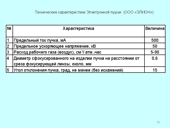
Design of the electron source Parameters of electron source: Accelerating voltage 2 -25 k. V Discharge current 0, 1 – 1 А Electron beam current 0, 1 -0, 5 А Maximal beam power 7 k. W Working gas air, methane, helium Gas pressure 1 – 20 Pa Working regime: DC Beam diameter 2 -5 mm 1 – water input, 2 – case, 3 – water resistor, 4 – hollow cathode, 5 – clamp, 6 – anode, 7 – holder, 8– extractor, 9, 12–water shirts, 10–basic flange, 11– focusing system 19
 (b) (c) a – front view, b – back")
View of electron source (a) (b) (c) a – front view, b – back view, c – without body. 20

Generation of ribbon electron beam 1 -hollow cathode; 2 -insertions; 3 -anode; 4, 5 -insulators; 6 -probe; 7 -accelerating electrode; 8 -movable collector. 21
 Accelerating voltage: 1 -6 k. V Beam")
Ribbon beam fore-pump plasma electron gun (design) Accelerating voltage: 1 -6 k. V Beam current: 0. 1 - 1 A Working gas: air, argon Gas pressure: 10 – 60 m. Torr Beam cross-section: 250 x 10 mm 22
 Electron gun Electron beam 23")
Ribbon beam fore-pump plasma electron gun (design) Electron gun Electron beam 23

Electron beam formation Axial magnetic field confines plasma at the system axis allows to increase beam currents 24

Beam interaction with isolated target 1 – electron source, 2 – vacuum chamber, 3 – electron beam, 4 – focusing system, 5 – target, 6 – voltmeter, 7 – plasma, 8 – probe. 25

Electron beam interaction with quartz target beam target 26

Collector potential depends on relationship between beam cross-section and collector area 1, 2, 3 – source electrodes, 4 – focusing system, 5 - electron beam, 6 - collector, 7 – insulating holder, 8 - grounded platform. 27 6
- Slides: 27