Ignition Systems Chapter 10 Basic Ignition System Operation

Ignition Systems Chapter #10

Basic Ignition System Operation • To provide sufficient voltage to discharge a spark between the electrodes of a spark plug.

Ignition System Components • Most small engine use a magneto system or variation. Magneto is specific to a points system, but is used universally to describe various ignition systems. You decide what language you want to use… Control module… Ignition module… – Permanent magnet – Spark plug – Sparkplug wire – Ignition coil – Switching device

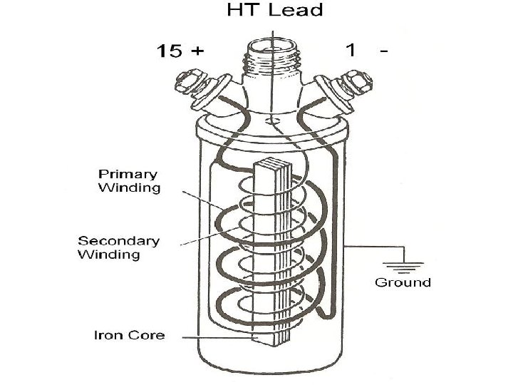
Ignition Coil

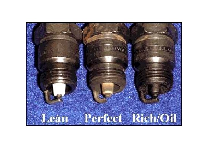
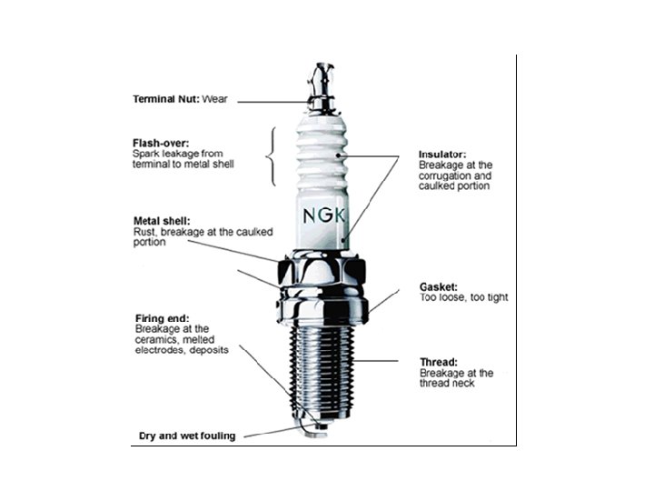
Spark Plugs

Spark Plugs

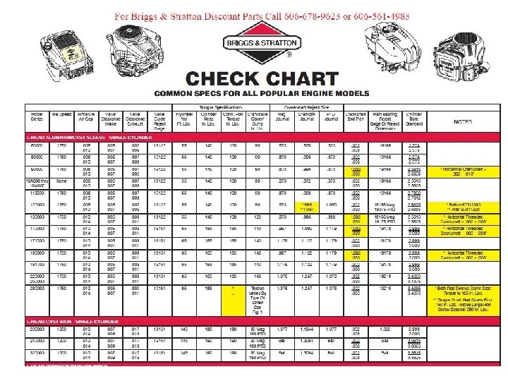
What is the gap? • Look it up… . 023 -. 030 ? ? ?

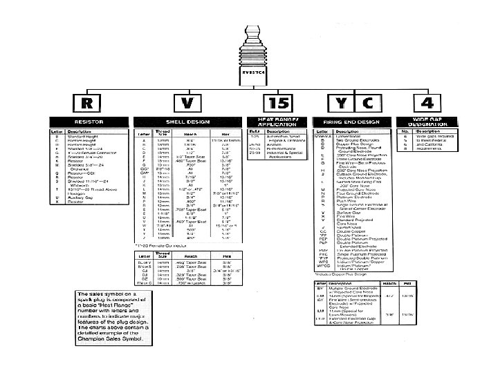
Spark Plug Code Interpretation

Plugs? ? ? • Replace every 100 hrs. or first sign of hard starting. • Torque: Alum. head 210 in/lbs Cast iron head 300 in/lbs • Battered or clogged threads M 14 X 1. 25 metric tap • Heli-coil - Thread insert

Plug Brand? • Briggs uses Champion. • I use NGK or Bosch. • What will you use?

Spark Plug Heat Transfer • Heat range

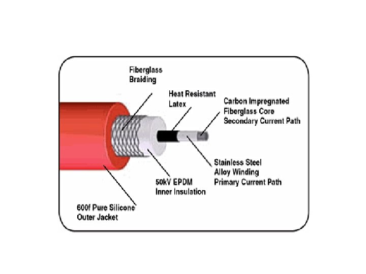
Spark Plug Wire

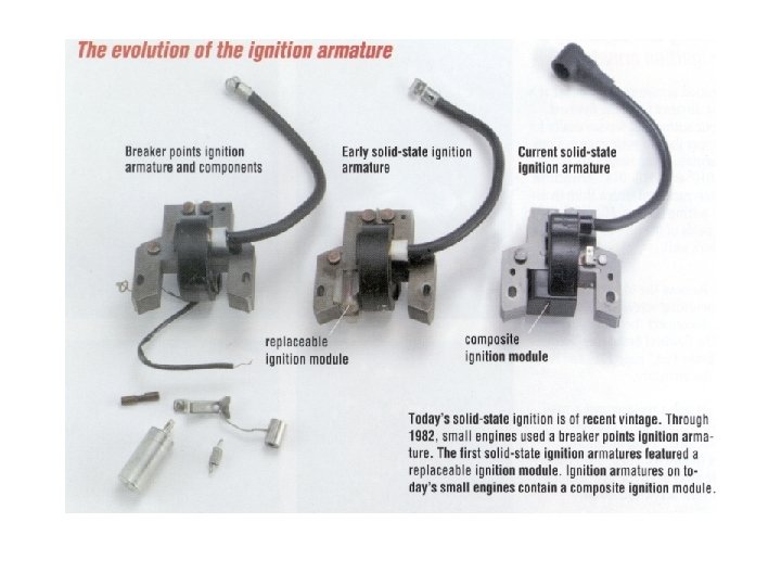
Switching Devices • Trigger collapsing field in primary coil – inducing a high voltage in secondary coil – firing plug – igniting fuel/air mixture – driving piston down on power stroke • Mechanical • Electronic

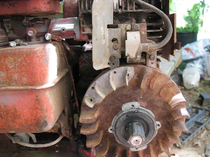
Flywheel - it’s magnetic…

Removal - Flywheel • Starter drive – tool 19163 • Puller • Shocker

Key and keyway • Briggs uses soft aluminum • Other manufactures use steel • Replace flywheel or hub if worn. Magnets seldom wear out. Should attract screwdriver 5/8”away. CDI uses weaker magnets.

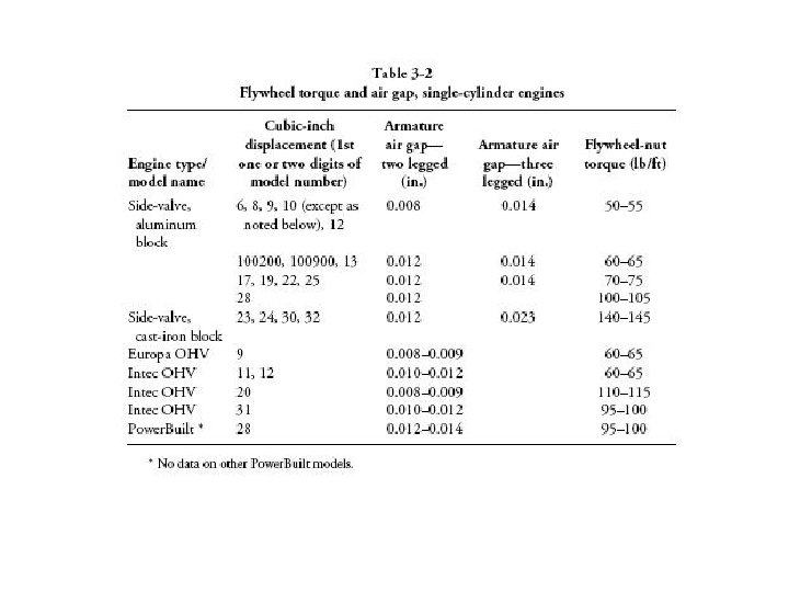
Installing Flywheel • • Clean crankshaft Bellville washer convex side up 30 wt. oil on bolt threads Torque – Engines >6 CID – 40 ft/lbs – 6 to 10 CID – 55 to 60 ft/lbs – 11 to 20 CID – 85 to 90 ft/lbs
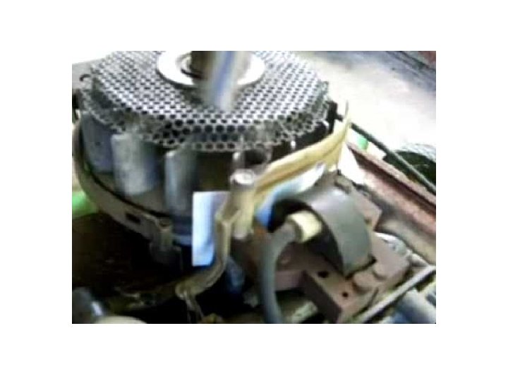
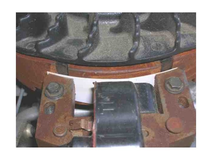

Use a business card

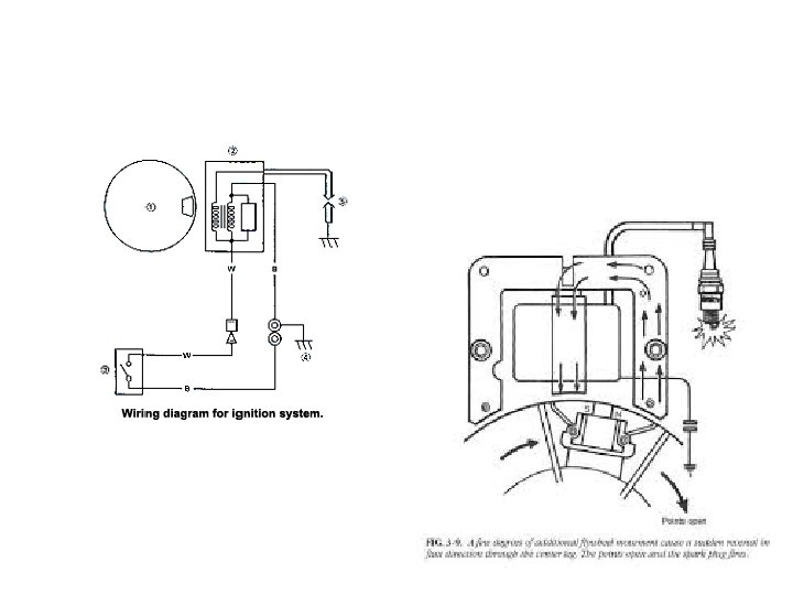
Magneto Ignition Systems
")
Capacitive Discharge Ignition (CDI)

CDI Ignition… • • • Do not run with battery disconnected… Kohler Smart Spark CDI Do not run with plug wire disconnected.

• Flywheel magnets generate 200 VAC in the input coil • The Rectifier converts the AC output to DC storage in the capacitor • The SCR (silicon controlled rectifier) remains non-conductive to block capacitor discharge • About 180 degrees later flywheel magnet sweeps past the trigger coil to generate signal voltage across the resistor – this causes the SCR the conduct • The stored charge on the capacitor discharges through the primary side of the pulse transformer • Current flow in the primary side of the pulse transformer (actually the ignition coil) generates a 25 K Volt potential in the secondary windings that goes to ground across the spark-plug electrodes • Caution: Solid-state components are vulnerable to stray and reversedpolarity voltage

Troubleshooting • • • Replace plug Replace key is distorted or sheared Check wiring, dielectric grease on contentions Ignition interlock Test unit (special tool) or replace with know good unit
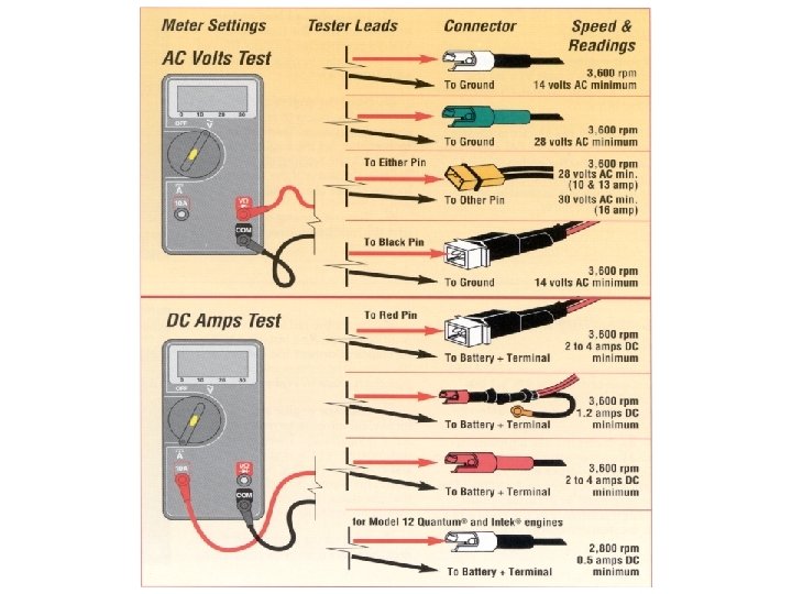
 • Magnetron • Plug terminal and engine ground 3 K –")
Transistor-Controlled Ignition (TCI) • Magnetron • Plug terminal and engine ground 3 K – 5 K Ohms.

Darlington Transistor Used for amplification…
m")
Mechanical Breaker Point Ignition (MBI)m
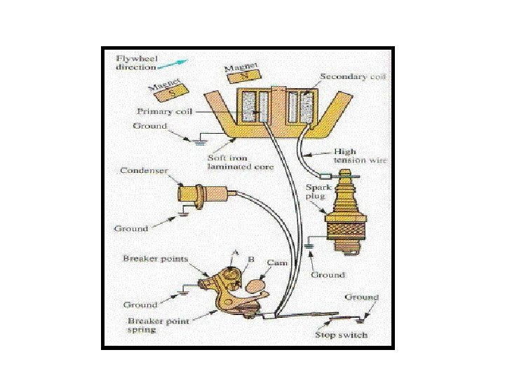


• Test ign. Circuit • W or W/O plug

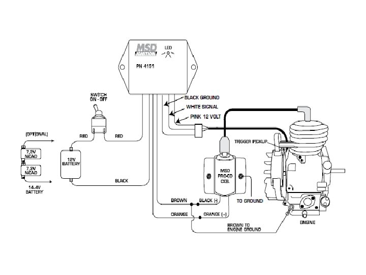
MSD • The MSD Enhancer system for the Briggs & Stratton/Tecumseh is designed as a complete system. The system has 12 Volts DC operating voltage, 14, 000 (1 Cylinder) rpm range, 100 MJ energy output maximum, 14° – 18° (1 Cylinder) multi spark duration, 1. 5 AMPS @ 10, 000 RPM current requirements, Primary 450 Volts voltage output, and 30, 000+ VOLTS with MSD Coil secondary voltage. The following schematic shows the MSD Briggs & Stratton/Tecumseh Ignition System Wiring Diagram.

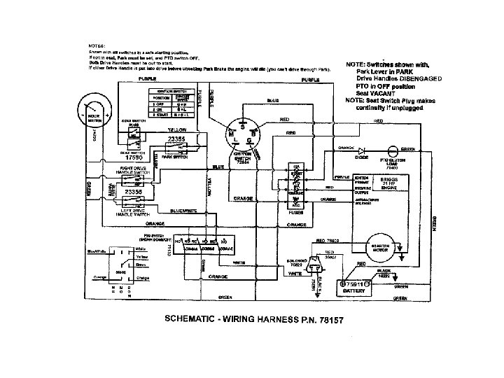
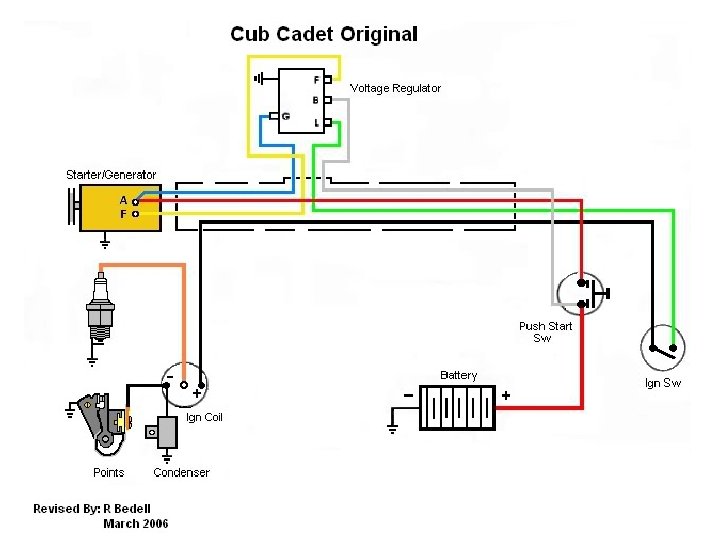
Battery Ignition Systems • Textbook pages 208 -209 – Figure 10 -24, 10 -25, & 10 -26

The Lead-Acid Battery • 6 cells, each cell 2. 105 V • Discharge rate 3 -20% month • 500 -800 cycles

Batteries Cont. • • • Explosion – Hydrogen Recycling Baking soda or ammonia Sulfating and DE sulfating Types of Batteries State of Charge Specific Gravity Voltage 12 V 6 V 100% 1. 265 12. 7 6. 3 75% 1. 225 12. 4 6. 2 50% 1. 190 12. 2 6. 1 25% 1. 155 12. 0 6. 0 Discharged 1. 120 11. 9 6. 0

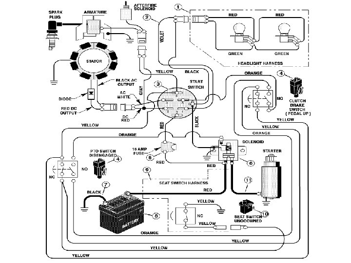
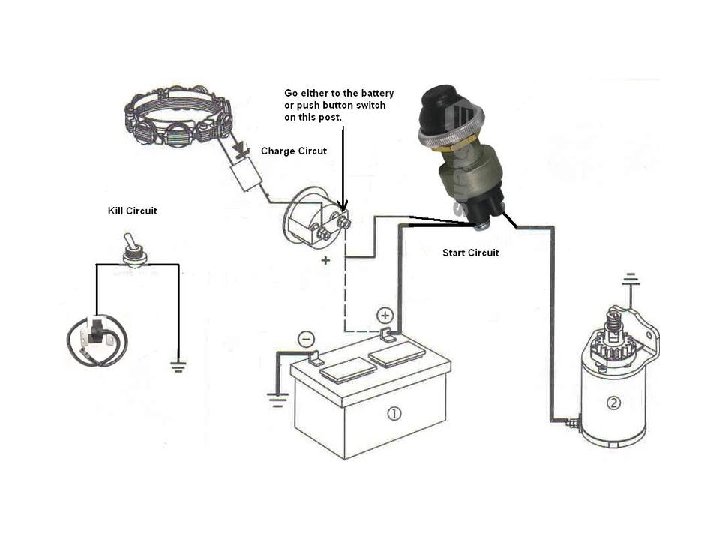
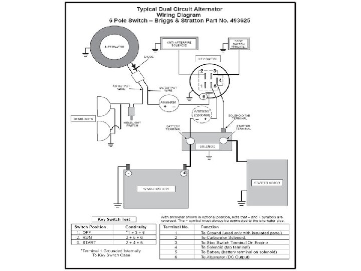
Electrical System Simplified
- Slides: 56