
IEC 61850 9 2 conformance test and the

- Slides: 18
IEC 61850 -9 -2 conformance test and the required network bandwidth Smart Grid Testing department Woohyun Seo
Contents 1. Merging Unit • Introduction, Advantages, Standards 2. Tripping in Process Bus 3. Conformance test 4. Network Bandwidth for Process Bus 5. Conclusion
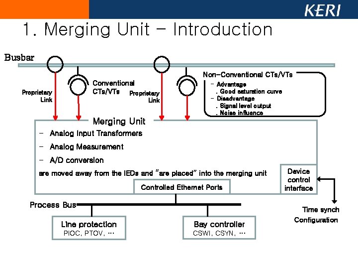
1. Merging Unit - Introduction Busbar Non-Conventional CTs/VTs Proprietary Link - Advantage. Good saturation curve - Disadvantage. Signal level output. Noise influence Merging Unit - Analog Input Transformers - Analog Measurement - A/D conversion are moved away from the IEDs and “are placed” into the merging unit Controlled Ethernet Ports Process Bus Line protection Bay controller PIOC, PTOV, … CSWI, CSYN, … Device control interface Time synch Configuration
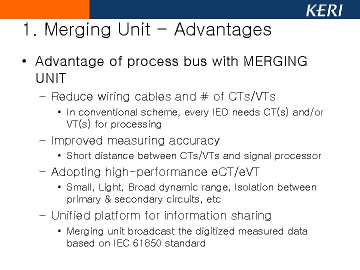
1. Merging Unit - Advantages • Advantage of process bus with MERGING UNIT – Reduce wiring cables and # of CTs/VTs • In conventional scheme, every IED needs CT(s) and/or VT(s) for processing – Improved measuring accuracy • Short distance between CTs/VTs and signal processor – Adopting high-performance e. CT/e. VT • Small, Light, Broad dynamic range, Isolation between primary & secondary circuits, etc – Unified platform for information sharing • Merging unit broadcast the digitized measured data based on IEC 61850 standard
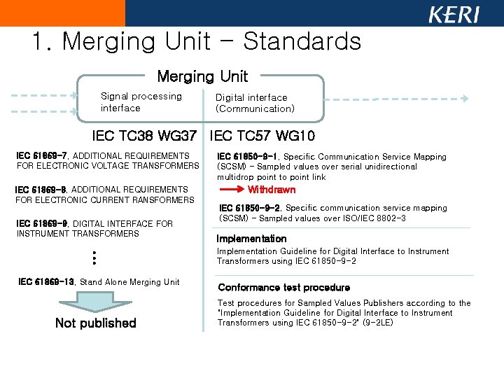
1. Merging Unit - Standards Merging Unit Signal processing interface Digital interface (Communication) IEC TC 38 WG 37 IEC TC 57 WG 10 IEC 61869 -7, ADDITIONAL REQUIREMENTS FOR ELECTRONIC VOLTAGE TRANSFORMERS IEC 61869 -8, ADDITIONAL REQUIREMENTS FOR ELECTRONIC CURRENT RANSFORMERS IEC 61869 -9, DIGITAL INTERFACE FOR INSTRUMENT TRANSFORMERS … IEC 61869 -13, Stand Alone Merging Unit Not published IEC 61850 -9 -1, Specific Communication Service Mapping (SCSM) – Sampled values over serial unidirectional multidrop point to point link Withdrawn IEC 61850 -9 -2, Specific communication service mapping (SCSM) – Sampled values over ISO/IEC 8802 -3 Implementation Guideline for Digital Interface to Instrument Transformers using IEC 61850 -9 -2 Conformance test procedure Test procedures for Sampled Values Publishers according to the "Implementation Guideline for Digital Interface to Instrument Transformers using IEC 61850 -9 -2" (9 -2 LE)
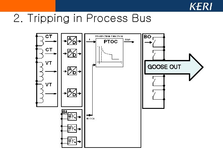
2. Tripping in Process Bus GOOSE OUT
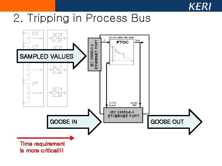
2. Tripping in Process Bus SAMPLED VALUES GOOSE IN Time requirement is more critical!!! GOOSE OUT
2. Tripping in Process Bus • A/D signal processing time delay – Primary condition for available protection • Guideline : 3 ms (IEC 60044 -8) • Packet jitter and latency control – Part of performance test • Only the total number of packets in 1 sec existed • Standard based syntax – Following IEC 61850 -9 -2 and IEC 61869 series • Network bandwidth – Lack of bandwidth makes packet loss • Out of range from conformance test
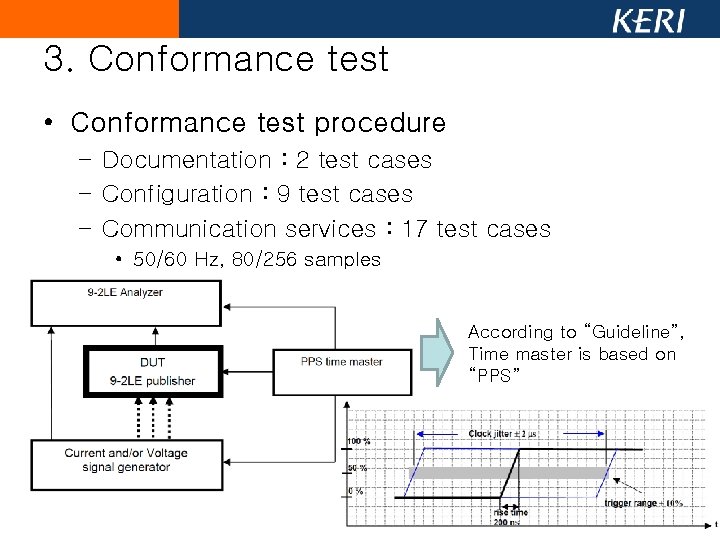
3. Conformance test • Conformance test procedure – Documentation : 2 test cases – Configuration : 9 test cases – Communication services : 17 test cases • 50/60 Hz, 80/256 samples According to “Guideline”, Time master is based on “PPS”
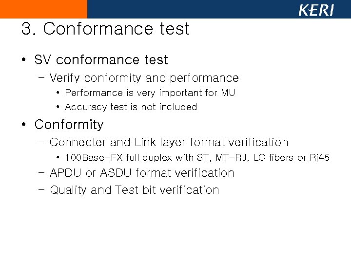
3. Conformance test • SV conformance test – Verify conformity and performance • Performance is very important for MU • Accuracy test is not included • Conformity – Connecter and Link layer format verification • 100 Base-FX full duplex with ST, MT-RJ, LC fibers or Rj 45 – APDU or ASDU format verification – Quality and Test bit verification
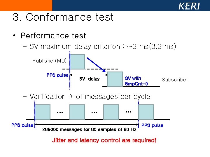
3. Conformance test • Performance test – SV maximum delay criterion : ~3 ms(3. 3 ms) Publisher(MU) PPS pulse SV delay SV with Smp. Cnt=0 Subscriber – Verification # of messages per cycle … PPS pulse … … 288000 messages for 80 samples of 60 Hz PPS pulse Jitter and latency control are required!
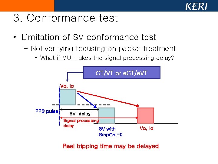
3. Conformance test • Limitation of SV conformance test – Not verifying focusing on packet treatment • What if MU makes the signal processing delay? CT/VT or e. CT/e. VT Vo, Io PPS pulse SV delay Signal processing delay SV with Smp. Cnt=0 Vo, Io Real tripping time may be delayed
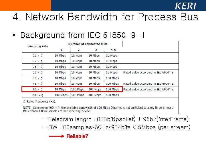
4. Network Bandwidth for Process Bus • Background from IEC 61850 -9 -1 – Telegram length : 888 bit(packet) + 96 bit(inter. Frame) – BW : 80 samples*60 Hz*984 bits < 5 Mbps (per stream) Reliable?
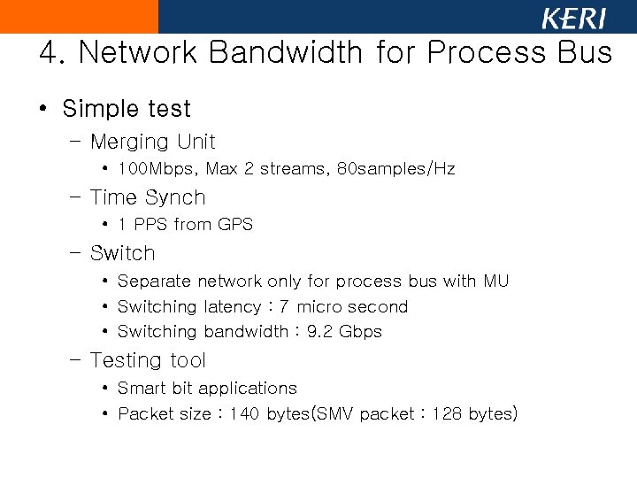
4. Network Bandwidth for Process Bus • Simple test – Merging Unit • 100 Mbps, Max 2 streams, 80 samples/Hz – Time Synch • 1 PPS from GPS – Switch • Separate network only for process bus with MU • Switching latency : 7 micro second • Switching bandwidth : 9. 2 Gbps – Testing tool • Smart bit applications • Packet size : 140 bytes(SMV packet : 128 bytes)
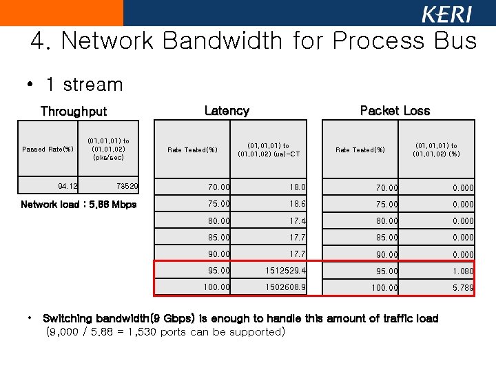
4. Network Bandwidth for Process Bus • 1 stream Latency Throughput Passed Rate(%) 94. 12 (01, 01) to (01, 02) (pks/sec) Rate Tested(%) Packet Loss (01, 01) to (01, 02) (us)-CT Rate Tested(%) (01, 01) to (01, 02) (%) 73529 70. 00 18. 0 70. 000 Network load : 5. 88 Mbps 75. 00 18. 6 75. 00 0. 000 80. 00 17. 4 80. 000 85. 00 17. 7 85. 00 0. 000 90. 00 17. 7 90. 000 95. 00 1512529. 4 95. 00 1. 080 100. 00 1502608. 9 100. 00 5. 789 • Switching bandwidth(9 Gbps) is enough to handle this amount of traffic load (9, 000 / 5. 88 = 1, 530 ports can be supported)
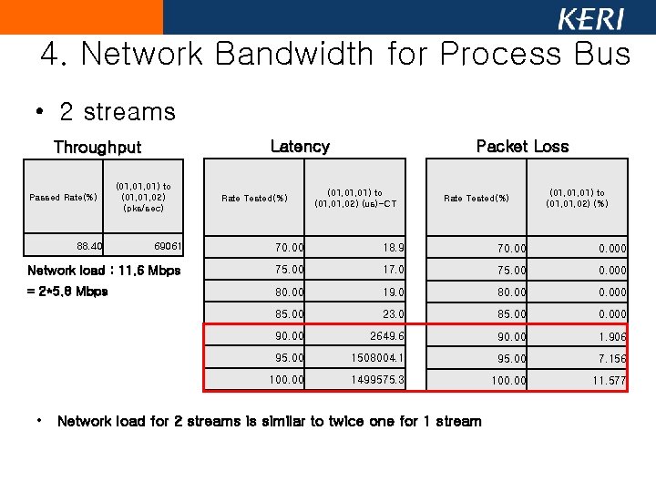
4. Network Bandwidth for Process Bus • 2 streams Latency Throughput Passed Rate(%) 88. 40 (01, 01) to (01, 02) (pks/sec) Rate Tested(%) Packet Loss (01, 01) to (01, 02) (us)-CT Rate Tested(%) (01, 01) to (01, 02) (%) 69061 70. 00 18. 9 70. 000 Network load : 11. 6 Mbps 75. 00 17. 0 75. 00 0. 000 = 2*5. 8 Mbps 80. 00 19. 0 80. 000 85. 00 23. 0 85. 00 0. 000 90. 00 2649. 6 90. 00 1. 906 95. 00 1508004. 1 95. 00 7. 156 100. 00 1499575. 3 100. 00 11. 577 • Network load for 2 streams is similar to twice one for 1 stream
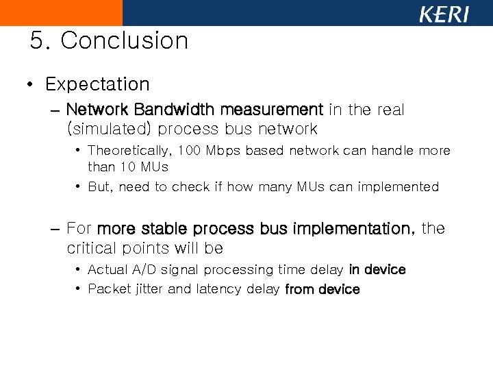
5. Conclusion • Expectation – Network Bandwidth measurement in the real (simulated) process bus network • Theoretically, 100 Mbps based network can handle more than 10 MUs • But, need to check if how many MUs can implemented – For more stable process bus implementation, implementation the critical points will be • Actual A/D signal processing time delay in device • Packet jitter and latency delay from device
Thank you for listening Any Questions? Whseo@keri. re. kr 031 -8040 -4421