
Ideal Diode Equation Topics of This Lecture Ideal




- Slides: 31
Ideal Diode Equation
Topics of This Lecture • Ideal Diode Equation – Its origins – Current versus Voltage (I-V) characteristics – How to calculate the magnitude of the variables in the equation using real data – What the limitations of this equation are – How it is used in PSpice simulations
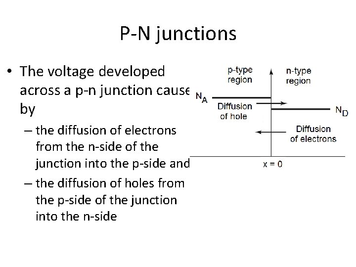
P-N junctions • The voltage developed across a p-n junction caused by – the diffusion of electrons from the n-side of the junction into the p-side and – the diffusion of holes from the p-side of the junction into the n-side
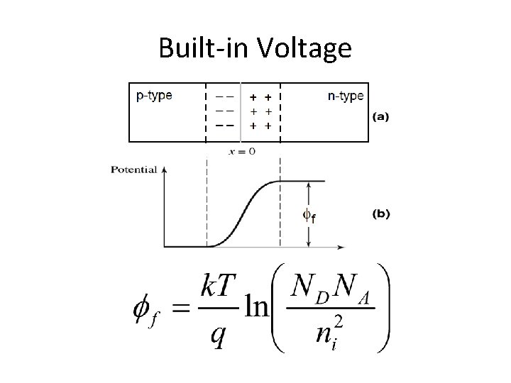
Built-in Voltage
Reminder • Drift currents only flow when there is an electric field present. • Diffusion currents only flow when there is a concentration difference for either the electrons or holes (or both).
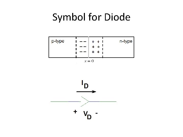
Symbol for Diode
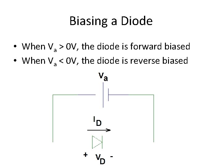
Biasing a Diode • When Va > 0 V, the diode is forward biased • When Va < 0 V, the diode is reverse biased
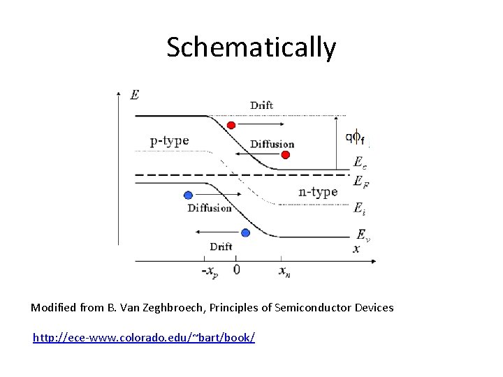
When the applied voltage (Va) is zero • The diode voltage and current are equal to zero on average – Any electron that diffuses through the depletion region from the n-side to the p-side is counterbalanced by an electron that drifts from the pside to the n-side – Any hole that diffuses through the depletion region from the p-side to the n-side is counterbalanced by an hole that drifts from the n-side to the p-side • So, at any one instant (well under a nanosecond), we may measure a diode current. This current gives rise to one of the sources of electronic noise.
Schematically Modified from B. Van Zeghbroech, Principles of Semiconductor Devices http: //ece-www. colorado. edu/~bart/book/
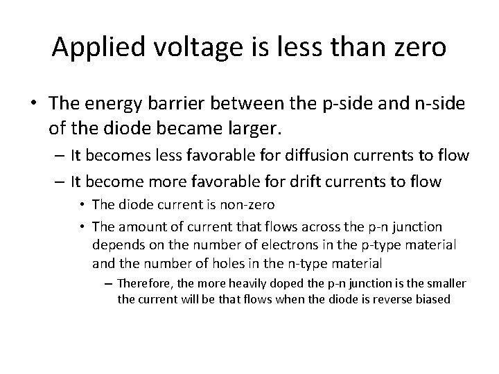
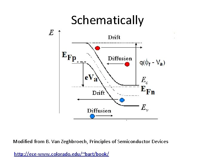
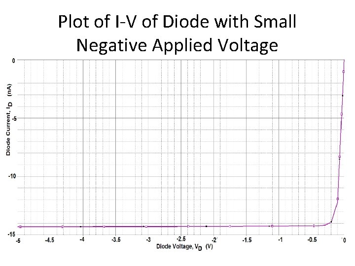
Applied voltage is less than zero • The energy barrier between the p-side and n-side of the diode became larger. – It becomes less favorable for diffusion currents to flow – It become more favorable for drift currents to flow • The diode current is non-zero • The amount of current that flows across the p-n junction depends on the number of electrons in the p-type material and the number of holes in the n-type material – Therefore, the more heavily doped the p-n junction is the smaller the current will be that flows when the diode is reverse biased
Schematically Modified from B. Van Zeghbroech, Principles of Semiconductor Devices http: //ece-www. colorado. edu/~bart/book/
Plot of I-V of Diode with Small Negative Applied Voltage
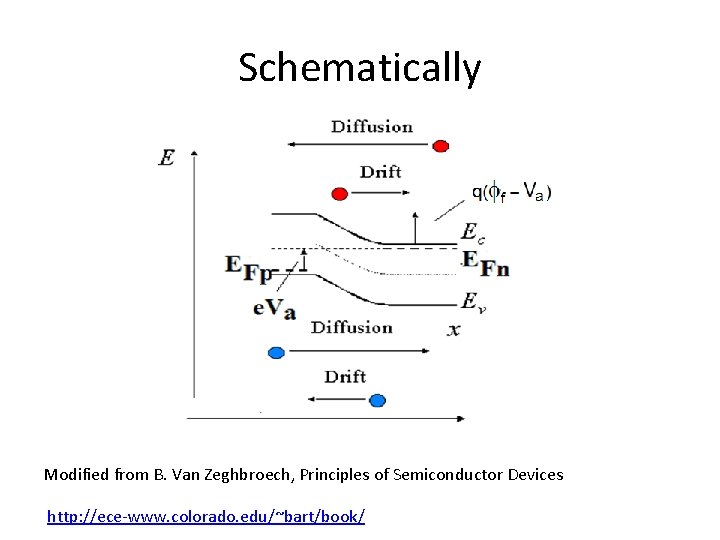
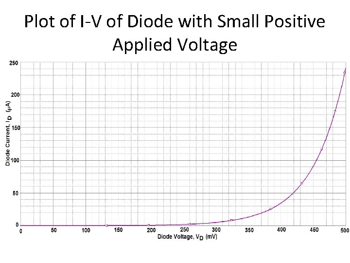
Applied Voltage is greater than zero • The energy barrier between the p-side and n-side of the diode became smaller with increasing positive applied voltage until there is no barrier left. – It becomes less favorable for drift currents to flow • There is no electric field left to force them to flow – There is nothing to prevent the diffusion currents to flow • The diode current is non-zero • The amount of current that flows across the p-n junction depends on the gradient of electrons (difference in the concentration) between the n- and p-type material and the gradient of holes between the p- and n-type material – The point at which the barrier becomes zero (the flat-band condition) depends on the value of the built-in voltage. The larger the built-in voltage, the more applied voltage is needed to remove the barrier. » It takes more applied voltage to get current to flow for a heavily doped p-n junction
Schematically Modified from B. Van Zeghbroech, Principles of Semiconductor Devices http: //ece-www. colorado. edu/~bart/book/
Plot of I-V of Diode with Small Positive Applied Voltage
Ideal Diode Equation • Empirical fit for both the negative and positive I-V of a diode when the magnitude of the applied voltage is reasonably small.
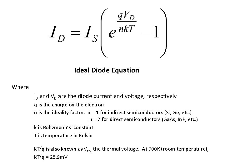
Ideal Diode Equation Where ID and VD are the diode current and voltage, respectively q is the charge on the electron n is the ideality factor: n = 1 for indirect semiconductors (Si, Ge, etc. ) n = 2 for direct semiconductors (Ga. As, In. P, etc. ) k is Boltzmann’s constant T is temperature in Kelvin k. T/q is also known as Vth, thermal voltage. At 300 K (room temperature), k. T/q = 25. 9 m. V
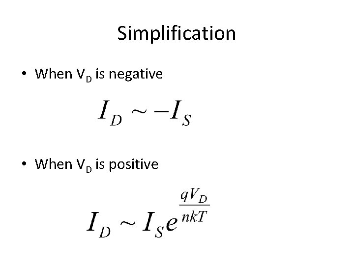
Simplification • When VD is negative • When VD is positive
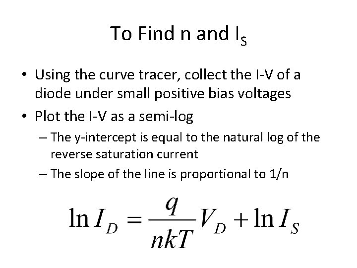
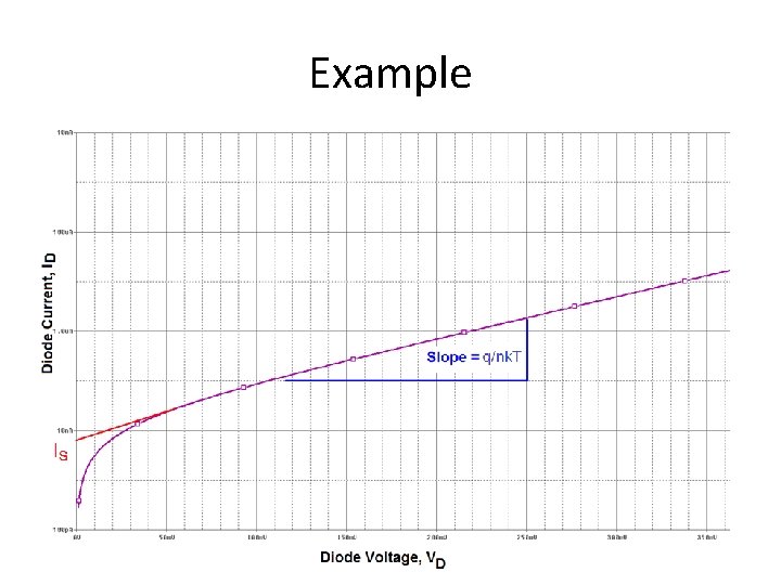
To Find n and IS • Using the curve tracer, collect the I-V of a diode under small positive bias voltages • Plot the I-V as a semi-log – The y-intercept is equal to the natural log of the reverse saturation current – The slope of the line is proportional to 1/n
Example
Questions • How does the I-V characteristic of a heavily doped diode differ from that of a lightly doped diode? • Why does the I-V characteristics differ? • For any diode, how does the I-V characteristic change as temperature increases? • For the same doping concentration, how does the I-V characteristic of a wide bandgap (EG) semiconductor compare to a narrow bandgap semiconductor (say Ga. As vs. Si)?
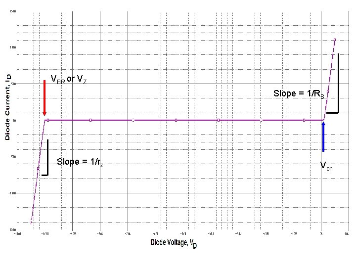
What the Ideal Diode Equation Doesn’t Explain • I-V characteristics under large forward and reverse bias conditions – Large current flow when at a large negative voltage (Breakdown voltage, VBR) – ‘Linear’ relationship between ID and VD at reasonably large positive voltages (Va > ff)
VBR or VZ Slope = 1/RS Slope = 1/rz Von
Nonideal (but real) I-V Characteristic • Need another model – Modifications to Ideal Diode Equation are used in PSpice • We will see this in the list of parameters in the device model – We will use a different model • It is called the Piecewise Model
PSpice • Simplest diode model in PSpice uses only the ideal diode equation • More complex diode models in PSpice include: – Parasitic resistances to account for the linear regions – Breakdown voltage with current multipliers to map the knee between Io and the current at breakdown – Temperature dependences of various parameters – Parasitic capacitances to account for the frequency dependence
Capture versus Schematics • It doesn’t matter to me which you use – I find Schematics easier, but the lab encourages the use of Capture
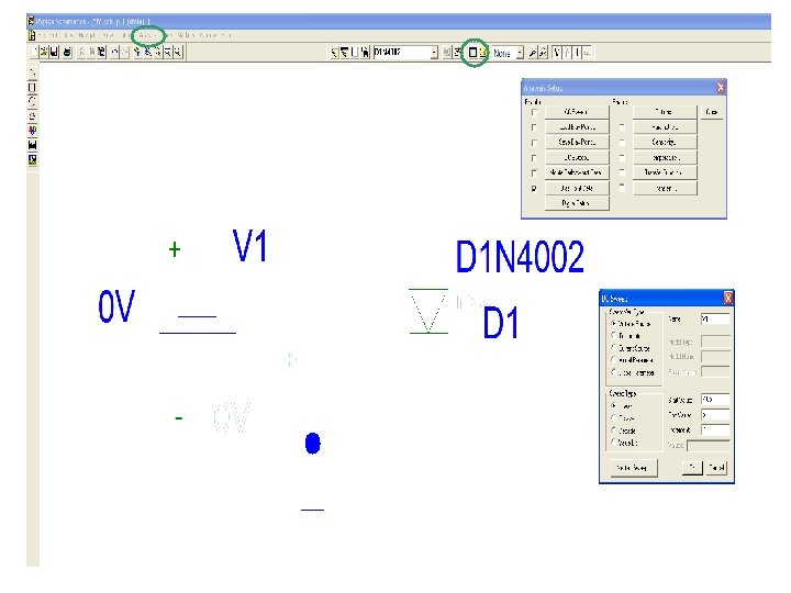
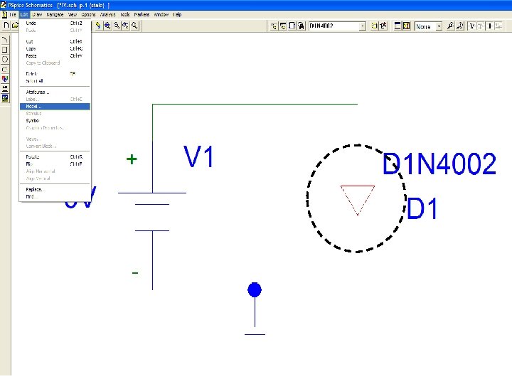
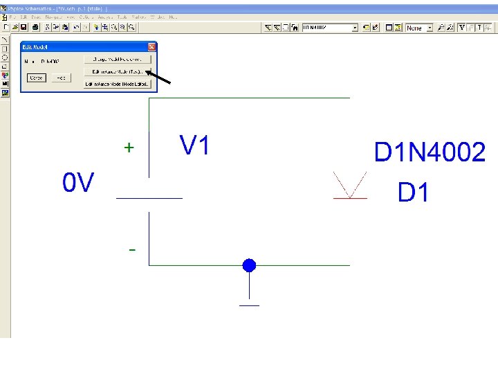
PSpice Schematics