I HVDC HVDC System HVDC Thyristor Valve Converter
,")


- Slides: 17
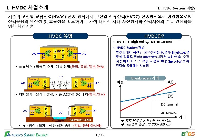
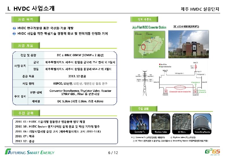
I. HVDC 사업소개 HVDC System 주요기기 HVDC시스템의 주요 기기로는 Thyristor Valve, Converter Transformer, C&P(Control&Protection), AC Filter 등이 있음 6% 22% DC Line 9% AC Line 8% 22% Civil Work : 16%, PJT Eng. : 17% HVDC Turnkey Cost Division (Base on 2 GW ±DC 500 k. V) 3 / 12
I. HVDC 사업소개 사업구조 및 조직도 국내 HVDC 사업구조 LSIS-조직도 CEO GE ALSTOM KEPCO • • Technical Support 연구개발본부 (CTO) 전력인프라사업본부 Project KAPES 국내 사 업부 • System Engineering HVDC 사업실 LSIS • Manufacturing HVDC 사업 개발 * KAPES : Kepco Alstom Power Electronics System * P/C : Power Conversion 4 / 12 부산 사업장 밸브 생산팀 HVDC Eng’g팀 C. TR 생산팀 천안 사업장 P/C 연구단 C&P 생산팀 HVDC C&P 연구팀 HVDC Valve 연구팀
별첨. 세부 기기 필요 사양 HVDC 기술 사양 DC Rating / Pole Specifications recommend Point to Point HVDC 250 km 2) Rated Power Capacity / pole 2000 MW Monopole/Rectifier Side 3) Rated Power Capacity / Bi-pole 4000 MW 1) DC System configuration 4) Rated DC Voltage DC ± 500 k. V 12 -pulse bridge 5) Rated DC current 4000 A normal 6) Overload DC current (not confirmed) 4800 A (1. 2 pu, 5 second) 7) Operation angle (not confirmed) α(normal rectifier delay angle) 17. 3 deg α(min. rectifier delay angle) 14. 7 deg α(max. rectifier delay angle) 19. 4 deg 22 deg γ(min. inverter extinction angle) 23. 7 deg γ(max. inverter extinction angle) 25. 3 deg γ(normal inverter extinction angle) 별첨. 1 / 3
별첨. 세부 기기 필요 사양 ± 500 k. V, 3000 MW, 북당진~고덕 HVDC DC CT절연레벨 Description Average Value Peak Value(리플 포함) lightning Impulse Withstand Level Switching Impulse Withstand Level DC withstand voltage level DC Polarity reversal Withstand Level Minimum Arcing Distance Minimum Creepage Distance HV side 513 k. Vdc 530 k. Vdc 1188 k. Vdc 1098 k. Vdc 770 k. Vdc 642 k. Vdc 3710 mm 10660 mm LV Side 2. 8 k. Vdc 3 k. Vdc 152 k. Vdc 139 k. Vdc 4. 2 k. Vdc 3. 5 k. Vdc 350 mm 60 mm DC VD절연레벨 Description Nominal Line to Ground Voltage(1 pu = Vn) Maximum Average Continuous Voltage to Ground Maximum Peack Continuous Voltage to Ground Maximum Measuring Voltage(for 5 sec) lightning Impulse Withstand Level Switching Impulse Withstand Level Minimum Creepage Distacne Minimum Clearrance to Ground 별첨. 2 / 3 HV side 505 k. Vdc 510 k. Vdc 530 k. Vdc 954 k. Vdc 1188 k. Vdc 1098 k. Vdc 10660 mm 3710 mm LV Side 3 k. Vdc 4 k. Vdc 6 k. Vdc 152 k. Vdc 139 k. Vdc 60 mm 350 mm
별첨. Single Line Diagram of HVDC ± 500 k. V, 2500 MW, Ballia-Bhiwadi HVDC 별첨. 3 / 3
질의/응답 Let’s talk 16