
HYDROPOWER Hydropower taps into the natural cycle of
- Slides: 12
HYDROPOWER • Hydropower taps into the natural cycle of – Solar heat sea water evaporation rainfall rivers sea • It is an established technology delivering ~20% of global electric production – By far the largest source of renewable energy • Energy of water is either potential (reservoirs) or kinetic (rivers). In both cases large water turbines are needed. • Tidal energy exploits bulk motion of water and requires lowhead water turbines • Wave power is a huge and largely untapped resource – Ocean waves transport 30 – 70 k. W of power per metre width – Need technologies to survive violent sea conditions – Best sites are between 40 o and 60 o latitudes on western coastlines above and below the equator 11/27/2020 Lecture 4 1
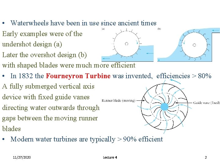
• Waterwheels have been in use since ancient times Early examples were of the undershot design (a) Later the overshot design (b) with shaped blades were much more efficient • In 1832 the Fourneyron Turbine was invented, efficiencies > 80% A fully submerged vertical axis device with fixed guide vanes directing water outwards through gaps between the moving runner blades • Modern water turbines are typically > 90% efficient 11/27/2020 Lecture 4 2
• Economic advantages include – Low operating costs, minimal impact on atmosphere, quick response to demand long plant life although the capital cost is high and there is a very long payback period • There are serious environmental and social issues – Displacement of population and impact on sedimentation, water quality, fish and flooding • Mountainous countries like Norway and Iceland are virtually self sufficient in hydropower • When resources are less abundant it is mainly used to satisfy peak load demand. • The following tables summarise the current world situation 11/27/2020 Lecture 4 3
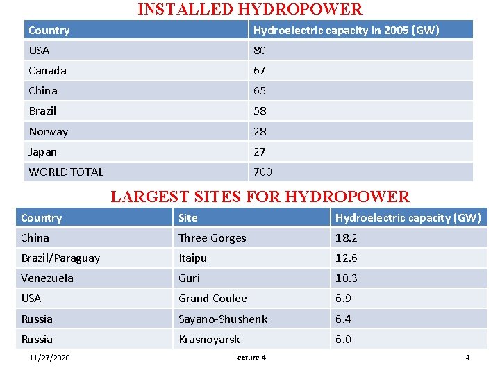
INSTALLED HYDROPOWER Country Hydroelectric capacity in 2005 (GW) USA 80 Canada 67 China 65 Brazil 58 Norway 28 Japan 27 WORLD TOTAL 700 LARGEST SITES FOR HYDROPOWER Country Site Hydroelectric capacity (GW) China Three Gorges 18. 2 Brazil/Paraguay Itaipu 12. 6 Venezuela Guri 10. 3 USA Grand Coulee 6. 9 Russia Sayano-Shushenk 6. 4 Russia Krasnoyarsk 6. 0 11/27/2020 Lecture 4 4
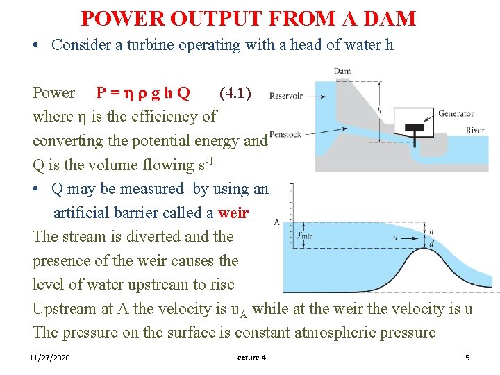
POWER OUTPUT FROM A DAM • Consider a turbine operating with a head of water h Power P = h r g h Q (4. 1) where h is the efficiency of converting the potential energy and Q is the volume flowing s-1 • Q may be measured by using an artificial barrier called a weir The stream is diverted and the presence of the weir causes the level of water upstream to rise Upstream at A the velocity is u. A while at the weir the velocity is u The pressure on the surface is constant atmospheric pressure 11/27/2020 Lecture 4 5
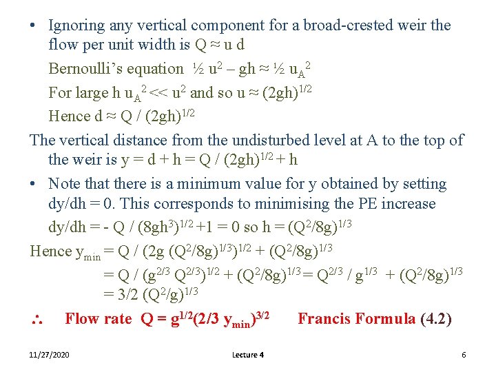
• Ignoring any vertical component for a broad-crested weir the flow per unit width is Q ≈ u d Bernoulli’s equation ½ u 2 – gh ≈ ½ u. A 2 For large h u. A 2 << u 2 and so u ≈ (2 gh)1/2 Hence d ≈ Q / (2 gh)1/2 The vertical distance from the undisturbed level at A to the top of the weir is y = d + h = Q / (2 gh)1/2 + h • Note that there is a minimum value for y obtained by setting dy/dh = 0. This corresponds to minimising the PE increase dy/dh = - Q / (8 gh 3)1/2 +1 = 0 so h = (Q 2/8 g)1/3 Hence ymin = Q / (2 g (Q 2/8 g)1/3)1/2 + (Q 2/8 g)1/3 = Q / (g 2/3 Q 2/3)1/2 + (Q 2/8 g)1/3 = Q 2/3 / g 1/3 + (Q 2/8 g)1/3 = 3/2 (Q 2/g)1/3 Flow rate Q = g 1/2(2/3 ymin)3/2 Francis Formula (4. 2) 11/27/2020 Lecture 4 6
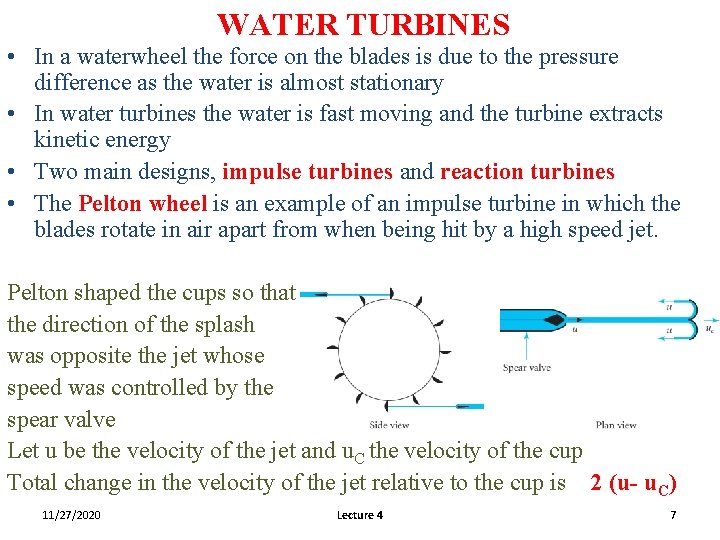
WATER TURBINES • In a waterwheel the force on the blades is due to the pressure difference as the water is almost stationary • In water turbines the water is fast moving and the turbine extracts kinetic energy • Two main designs, impulse turbines and reaction turbines • The Pelton wheel is an example of an impulse turbine in which the blades rotate in air apart from when being hit by a high speed jet. Pelton shaped the cups so that the direction of the splash was opposite the jet whose speed was controlled by the spear valve Let u be the velocity of the jet and u. C the velocity of the cup Total change in the velocity of the jet relative to the cup is 2 (u- u. C) 11/27/2020 Lecture 4 7
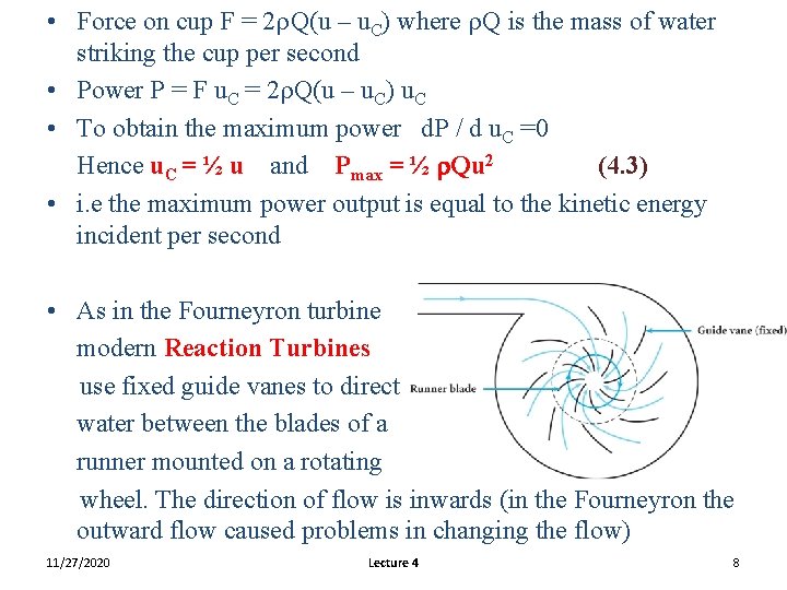
• Force on cup F = 2 r. Q(u – u. C) where r. Q is the mass of water striking the cup per second • Power P = F u. C = 2 r. Q(u – u. C) u. C • To obtain the maximum power d. P / d u. C =0 Hence u. C = ½ u and Pmax = ½ r. Qu 2 (4. 3) • i. e the maximum power output is equal to the kinetic energy incident per second • As in the Fourneyron turbine modern Reaction Turbines use fixed guide vanes to direct water between the blades of a runner mounted on a rotating wheel. The direction of flow is inwards (in the Fourneyron the outward flow caused problems in changing the flow) 11/27/2020 Lecture 4 8
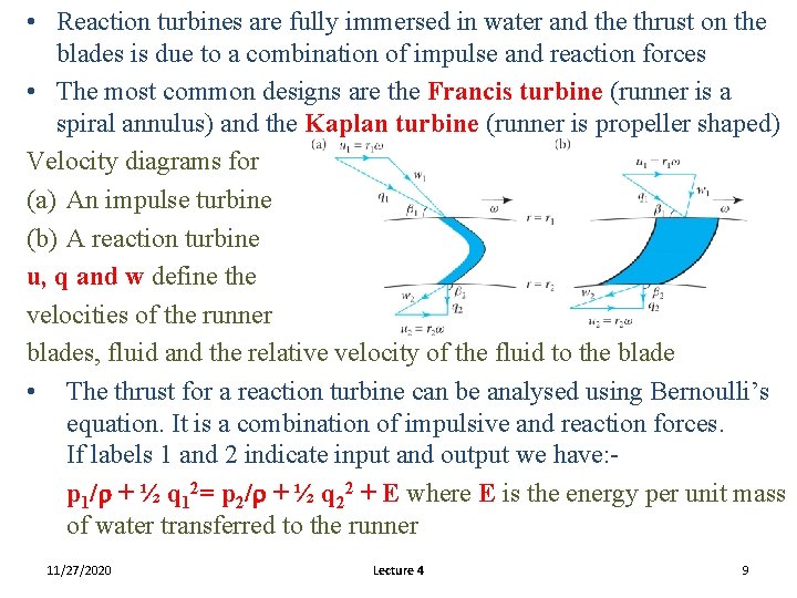
• Reaction turbines are fully immersed in water and the thrust on the blades is due to a combination of impulse and reaction forces • The most common designs are the Francis turbine (runner is a spiral annulus) and the Kaplan turbine (runner is propeller shaped) Velocity diagrams for (a) An impulse turbine (b) A reaction turbine u, q and w define the velocities of the runner blades, fluid and the relative velocity of the fluid to the blade • The thrust for a reaction turbine can be analysed using Bernoulli’s equation. It is a combination of impulsive and reaction forces. If labels 1 and 2 indicate input and output we have: p 1/r + ½ q 12= p 2/r + ½ q 22 + E where E is the energy per unit mass of water transferred to the runner 11/27/2020 Lecture 4 9
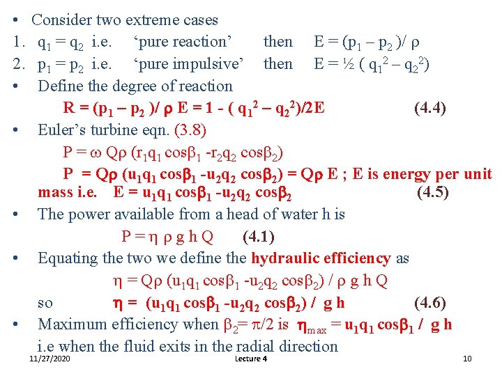
• 1. 2. • • • Consider two extreme cases q 1 = q 2 i. e. ‘pure reaction’ then E = (p 1 – p 2 )/ r p 1 = p 2 i. e. ‘pure impulsive’ then E = ½ ( q 12 – q 22) Define the degree of reaction R = (p 1 – p 2 )/ r E = 1 - ( q 12 – q 22)/2 E (4. 4) Euler’s turbine eqn. (3. 8) P = w Qr (r 1 q 1 cosb 1 -r 2 q 2 cosb 2) P = Qr (u 1 q 1 cosb 1 -u 2 q 2 cosb 2) = Qr E ; E is energy per unit mass i. e. E = u 1 q 1 cosb 1 -u 2 q 2 cosb 2 (4. 5) The power available from a head of water h is P=hrgh. Q (4. 1) Equating the two we define the hydraulic efficiency as h = Qr (u 1 q 1 cosb 1 -u 2 q 2 cosb 2) / r g h Q so h = (u 1 q 1 cosb 1 -u 2 q 2 cosb 2) / g h (4. 6) Maximum efficiency when b 2= p/2 is hmax = u 1 q 1 cosb 1 / g h i. e when the fluid exits in the radial direction 11/27/2020 Lecture 4 10
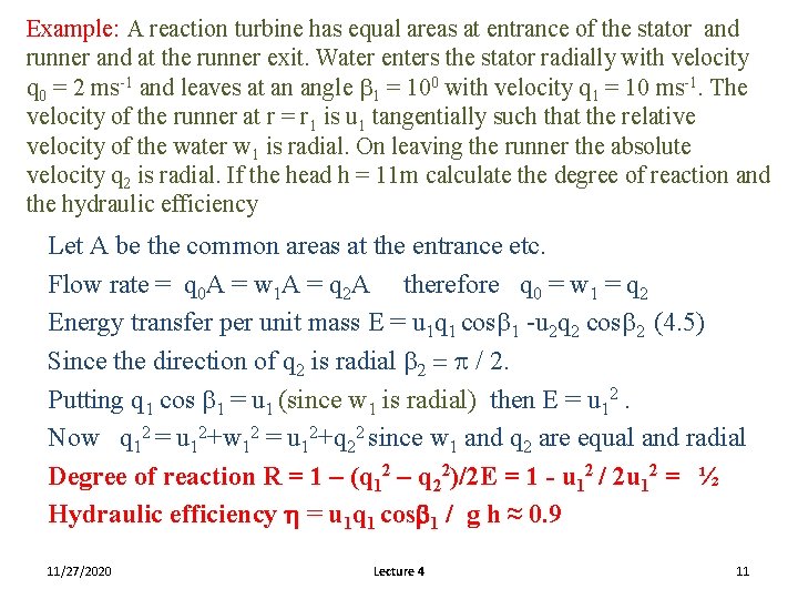
Example: A reaction turbine has equal areas at entrance of the stator and runner and at the runner exit. Water enters the stator radially with velocity q 0 = 2 ms-1 and leaves at an angle b 1 = 100 with velocity q 1 = 10 ms-1. The velocity of the runner at r = r 1 is u 1 tangentially such that the relative velocity of the water w 1 is radial. On leaving the runner the absolute velocity q 2 is radial. If the head h = 11 m calculate the degree of reaction and the hydraulic efficiency Let A be the common areas at the entrance etc. Flow rate = q 0 A = w 1 A = q 2 A therefore q 0 = w 1 = q 2 Energy transfer per unit mass E = u 1 q 1 cosb 1 -u 2 q 2 cosb 2 (4. 5) Since the direction of q 2 is radial b 2 = p / 2. Putting q 1 cos b 1 = u 1 (since w 1 is radial) then E = u 12. Now q 12 = u 12+w 12 = u 12+q 22 since w 1 and q 2 are equal and radial Degree of reaction R = 1 – (q 12 – q 22)/2 E = 1 - u 12 / 2 u 12 = ½ Hydraulic efficiency h = u 1 q 1 cosb 1 / g h ≈ 0. 9 11/27/2020 Lecture 4 11
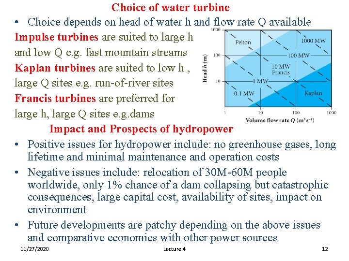
Choice of water turbine • Choice depends on head of water h and flow rate Q available Impulse turbines are suited to large h and low Q e. g. fast mountain streams Kaplan turbines are suited to low h , large Q sites e. g. run-of-river sites Francis turbines are preferred for large h, large Q sites e. g. dams Impact and Prospects of hydropower • Positive issues for hydropower include: no greenhouse gases, long lifetime and minimal maintenance and operation costs • Negative issues include: relocation of 30 M-60 M people worldwide, only 1% chance of a dam collapsing but catastrophic consequences, large capital cost, availability of sites, impact on environment • Future developments are patchy depending on the above issues and comparative economics with other power sources 11/27/2020 Lecture 4 12