HydroForming a Steel Tube Finite Element Model Design

Hydro-Forming a Steel Tube Finite Element Model Design Greg Wilmes Finite Element Method MIE 605 – Spring 2003

Hydro-Forming of a Steel Tube • Background • Model Creation – – – Model Limitations Contact elements Load stepping • Findings • Future Work • Conclusion

Background Hydro-Forming is a manufacturing process which forms complex shapes using uncompressible liquids. • Sheet Hydro-Forming – Hoods – Roofs • Tubular Hydro-Forming – Engine chassis – Frame Rails – Exhaust Systems

Primer: Tube Hydroforming a b c d e f Faxial P Derived from: Siempelkamp Pressen Systeme Gmb. H & Co. Massachusetts Institute of Technology Cambridge, Massachusetts

Concerns During Hydroforming Process

Focus of this project • Create a Finite Element Model to simulate the hydro-forming process • Use the model to create a 3”x 3” square tube from a 3” round tube.

Real World Example • 3 -D parts • Non-linear material • • • properties Material variations Complicated geometry with bends and depressions Friction

Geometry Simplifications • 2 -Dimensional • Symmetric • Deformation from Circle to Square • Rigid Target Surface • Constant Thickness 1. 6 mm

Governing Equation • Hoop Stress

Material Property Simplifications • Isotropic Expansion • Non-Linear – Experimental tensile test data – 20 points • Coloumb Friction Effects • No strain rate effects

Model Creation • Element Type – Plane 42 • 4 noded • 2 -Dimensional • Non-Linear • Options – Plane Stress Option – Local Coordinate System – Extra Shape Functions

Meshing • Hydro-Form Die – Rigid Target • No mesh allowed • Hydro-Form Blank – Mapped Mesh • Angled • Thickness split

Contact Elements • Allows modeling of • contact between two objects Used Contact Wizard – – – Rigid Target Deformable Contact No Separation (sliding) option – Coloumb Friction (0. 27)

Solution Control Options • Static – Quasi-Static Evaluation • Non-Linear Solution • Stepped Loading • Auto Time Steps

Constraints • Target Die – Fully constrained – Cannot Move • Contact Blank – Symmetrically Constrained

Load Steps • Using a simple “do” loop – Slowly increase internal pressure – 380 MPa • Used second “do” loop – Maintain pressure for a period of time • Repeated for different meshing configurations

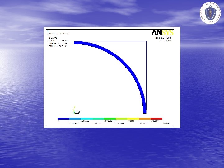
Findings • Difference between 90 elements and 1400 elements was • • 0. 032 mm 0. 3% difference Close to general manufacturing machining tolerances

Continued Work • Refine Finite Element simulation to match real world parts – 3 -Dimentions – Different materials – Different deformation shapes • Stress State analysis

Conclusion and Thoughts • The Finite Element Method and Ansys seem to be appropriate for analyzing this problem • Model seemed as respond well with about 100 elements
- Slides: 20