
HYDRAULICS PNEUMATICS Basic Pneumatic Circuits 1 Presented by
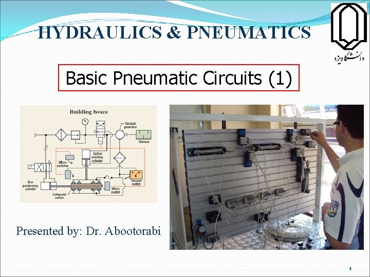
HYDRAULICS & PNEUMATICS Basic Pneumatic Circuits (1) Presented by: Dr. Abootorabi 1
Contents l l l Introduction Symbols Circuit layout Actuator control 2/2 Valve Actuator control 3/2 Valve l Actuator control 5/2 Valve l Sequential control Sequence solution 5/3 Valves l l 2
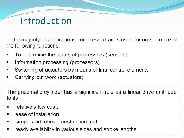
Introduction 3
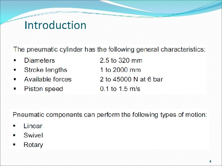
Introduction 4
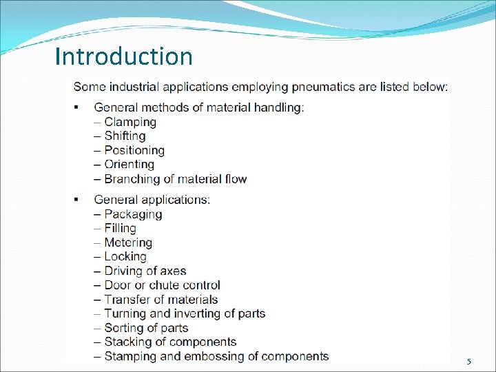
Introduction 5
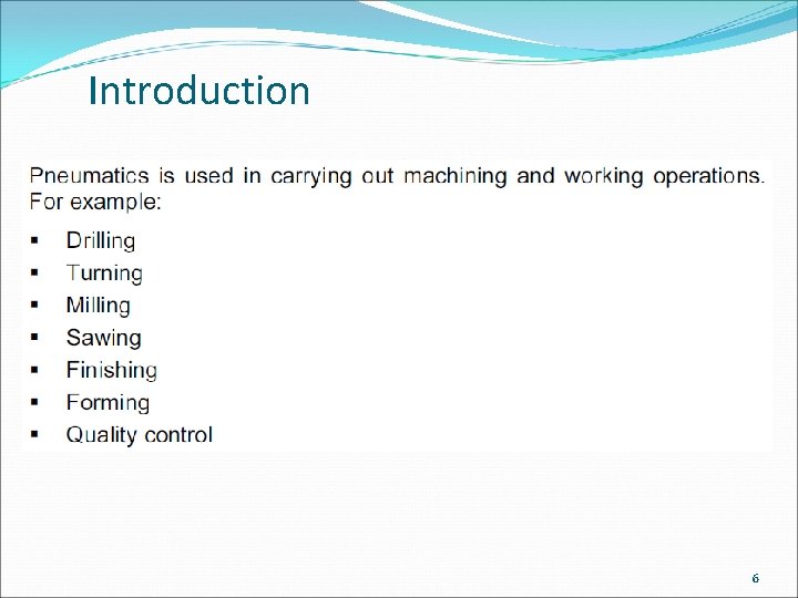
Introduction 6
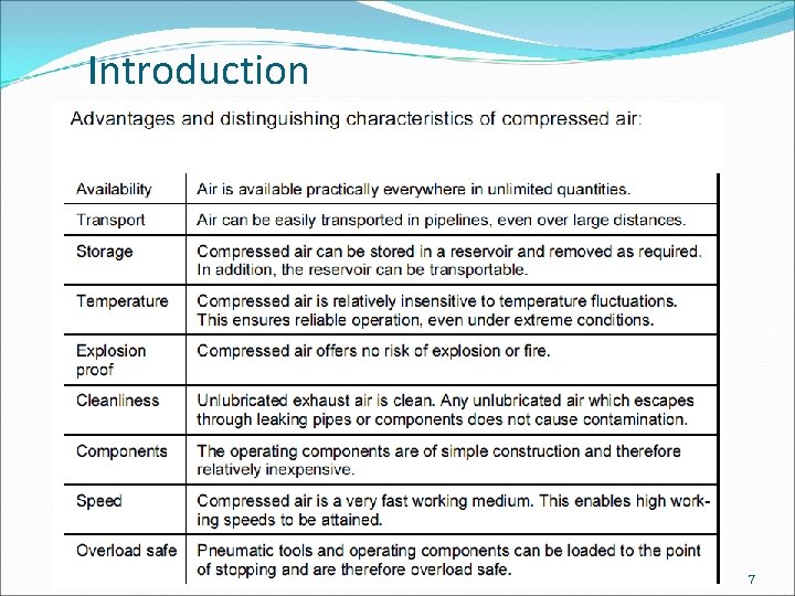
Introduction 7
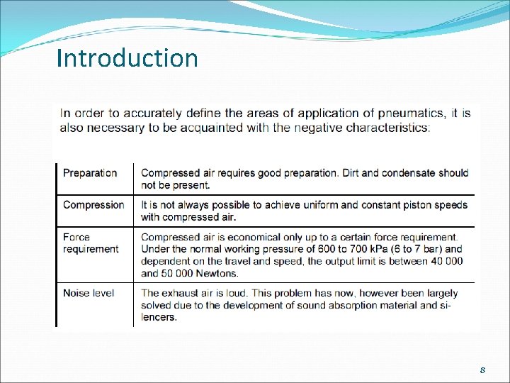
Introduction 8
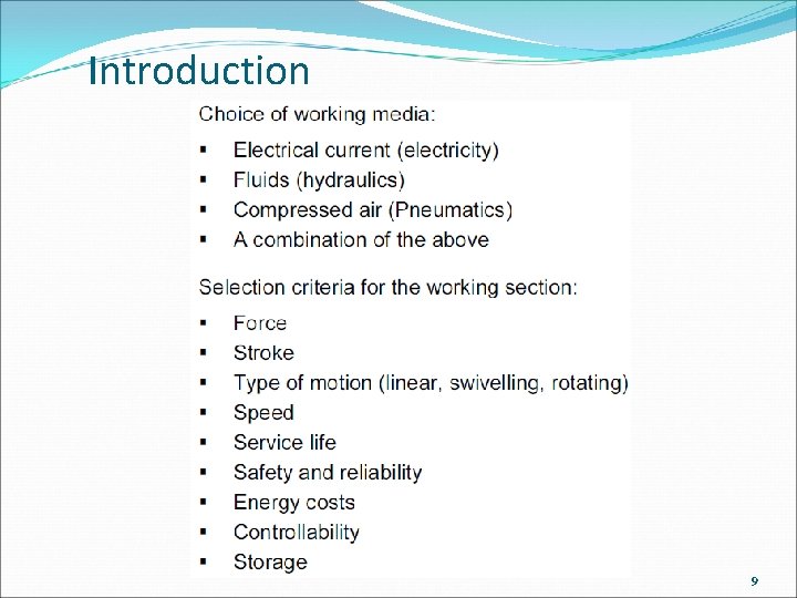
Introduction 9
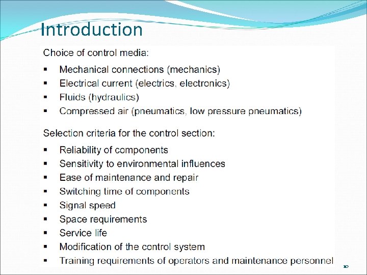
Introduction 10
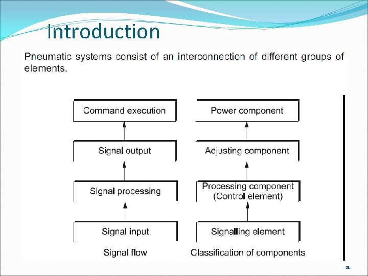
Introduction 11
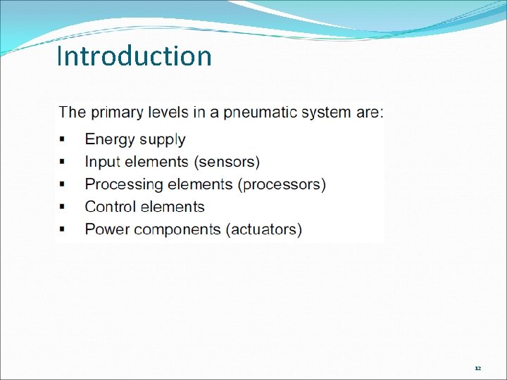
Introduction 12
Introduction 13

Introduction 14
Introduction This module shows the methods of application of pneumatic valves and components for control and automation. The methods of pure pneumatic sequential control are confined to simple examples. The majority of modern systems are controlled electronically and is the subject of electropneumatic modules. A message to pneumatic circuit designers: Use proven and design techniques reliable Produce circuits and documentation that are clear to read Design for safety Do not try to be too clever, the circuit will be difficult for others to read and maintain 15
Symbols and Standards in Pneumatics 16
Symbols and Standards in Pneumatics 17
Symbols and Standards in Pneumatics 18
Symbols and Standards in Pneumatics 19
Symbols and Standards in Pneumatics 20
Symbols and Standards in Pneumatics 21
Symbols and Standards in Pneumatics 22
Symbols and Standards in Pneumatics 23
Symbols and Standards in Pneumatics 24
Symbols and Standards in Pneumatics 25
Symbols and Standards in Pneumatics 26
Symbols and Standards in Pneumatics 27
Symbols and Standards in Pneumatics 28
Symbols and Standards in Pneumatics 29

Symbols and Standards in Pneumatics 30
Circuit layout The standard for circuit diagrams is ISO 1219 -2. A 4 format or A 3 folded to A 4 height for inclusion in a manual with other A 4 documentation. l Circuits should be drawn with all actuators at the top of the page in order of sequential operation. l Other components to be drawn in sequential order from the bottom up and from left to right. l Circuit should show the system with pressure applied and ready to start. To be on several sheets if necessary with line identification code. Minimum crossing lines. Limit valves position of operation by actuators shown by a marker with reference code to symbol. 31
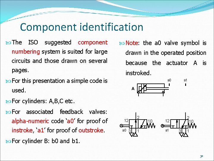
Component identification The ISO suggested component Note: the a 0 valve symbol is numbering system is suited for large drawn in the operated position circuits and those drawn on several because the actuator A is pages. instroked. For this presentation a simple code is a 0 a 1 A used. For cylinders: A, B, C etc. For associated feedback valves: alpha-numeric code ‘a 0’ for proof of instroke, ‘a 1’ for proof of outstroke. 12 a 0 3 2 1 10 2 10 12 a 1 3 1 For cylinder B: b 0 and b 1. 32
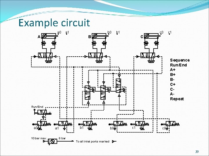
Example circuit a 0 a 1 b 0 A b 1 c 0 B c 1 C Sequence Run/End A+ B+ BC+ CARepeat Run/End a 0 10 bar max b 1 a 1 b 0 c 1 c 0 6 bar To all inlet ports marked 33
Actuator control 2/2 valve 34
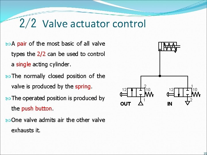
2/2 Valve actuator control A pair of the most basic of all valve types the 2/2 can be used to control a single acting cylinder. The normally closed position of the valve is produced by the spring. The operated position is produced by the push button. 12 OUT 2 10 1 12 IN 1 10 2 One valve admits air the other valve exhausts it. 35
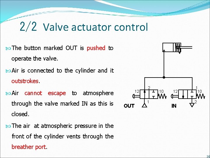
2/2 Valve actuator control The button marked OUT is pushed to operate the valve. Air is connected to the cylinder and it outstrokes. Air cannot escape to atmosphere through the valve marked IN as this is 12 OUT 2 1 10 12 IN 1 10 2 closed. The air at atmospheric pressure in the front of the cylinder vents through the breather port. 36
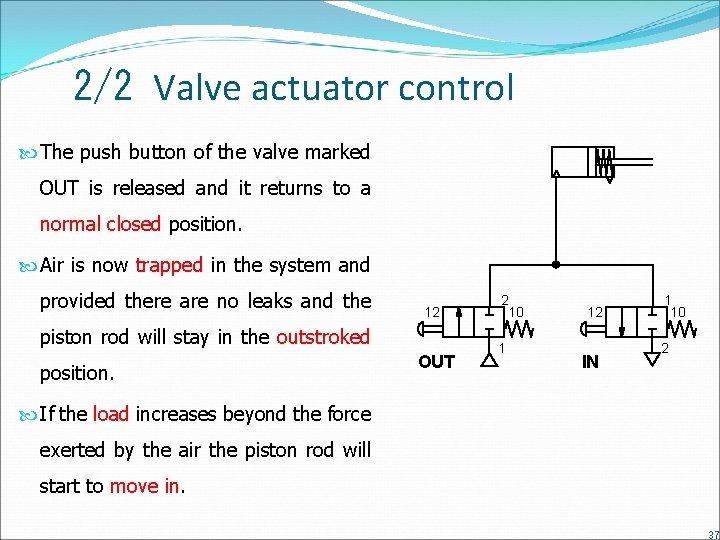
2/2 Valve actuator control The push button of the valve marked OUT is released and it returns to a normal closed position. Air is now trapped in the system and provided there are no leaks and the 12 piston rod will stay in the outstroked position. OUT 2 10 1 12 IN 1 10 2 If the load increases beyond the force exerted by the air the piston rod will start to move in. 37
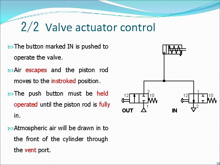
2/2 Valve actuator control The button marked IN is pushed to operate the valve. Air escapes and the piston rod moves to the instroked position. The push button must be held operated until the piston rod is fully in. 12 OUT 2 10 1 12 IN 1 10 2 Atmospheric air will be drawn in to the front of the cylinder through the vent port. 38
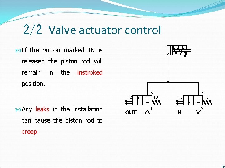
2/2 Valve actuator control If the button marked IN is released the piston rod will remain in the instroked position. 12 Any leaks in the installation OUT 2 10 1 12 IN 1 10 2 can cause the piston rod to creep. 39
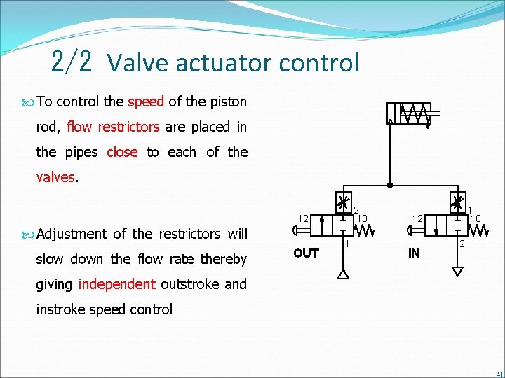
2/2 Valve actuator control To control the speed of the piston rod, flow restrictors are placed in the pipes close to each of the valves. 2 10 12 Adjustment of the restrictors will slow down the flow rate thereby OUT 1 1 10 12 IN 2 giving independent outstroke and instroke speed control 40
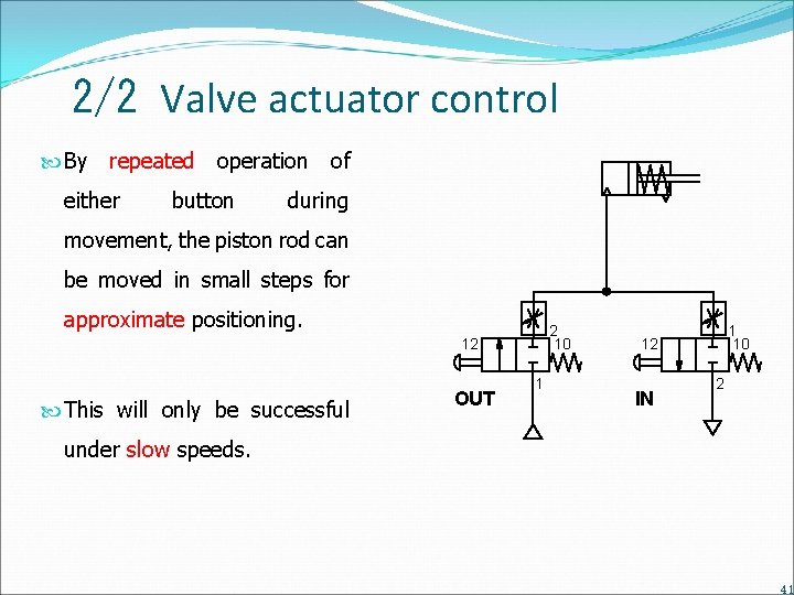
2/2 Valve actuator control By repeated operation of either button during movement, the piston rod can be moved in small steps for approximate positioning. 2 10 12 This will only be successful OUT 1 1 10 12 IN 2 under slow speeds. 41
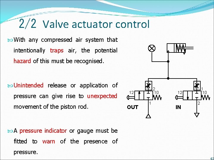
2/2 Valve actuator control With any compressed air system that intentionally traps air, the potential hazard of this must be recognised. Unintended release or application of pressure can give rise to unexpected movement of the piston rod. 2 10 12 OUT 1 1 10 12 IN 2 A pressure indicator or gauge must be fitted to warn of the presence of pressure. 42
Actuator control 3/2 valve 43
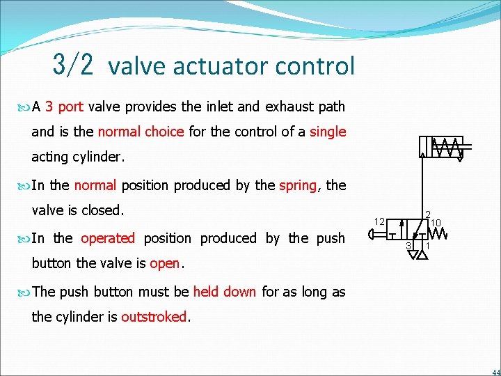
3/2 valve actuator control A 3 port valve provides the inlet and exhaust path and is the normal choice for the control of a single acting cylinder. In the normal position produced by the spring, the valve is closed. In the operated position produced by the push 2 10 12 3 1 button the valve is open. The push button must be held down for as long as the cylinder is outstroked. 44
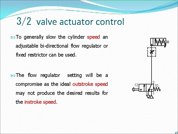
3/2 valve actuator control To generally slow the cylinder speed an adjustable bi-directional flow regulator or fixed restrictor can be used. The flow regulator setting will be a compromise as the ideal outstroke speed may not produce the desired results for 2 10 12 3 1 the instroke speed. 45
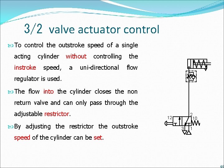
3/2 valve actuator control To control the outstroke speed of a single acting instroke cylinder speed, without a controlling uni-directional the flow regulator is used. The flow into the cylinder closes the non return valve and can only pass through the adjustable restrictor. By adjusting the restrictor the outstroke 2 10 12 3 1 speed of the cylinder can be set. 46
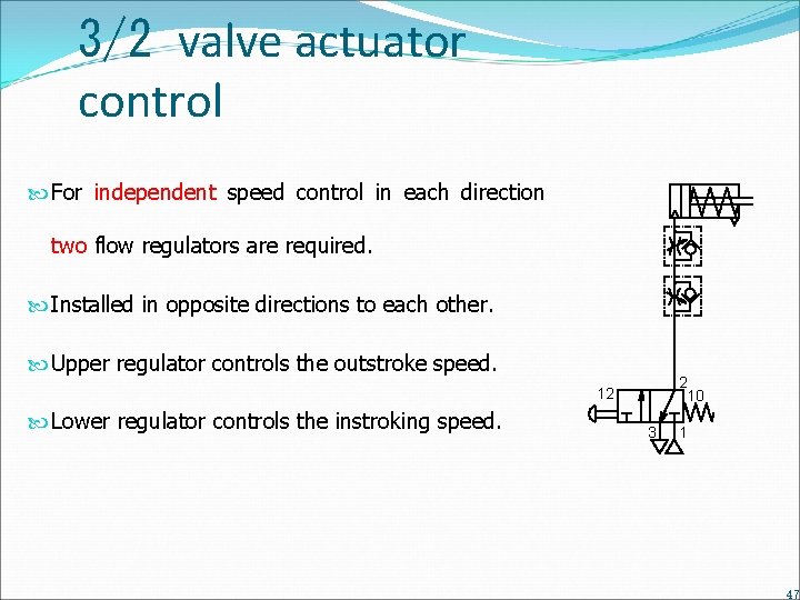
3/2 valve actuator control For independent speed control in each direction two flow regulators are required. Installed in opposite directions to each other. Upper regulator controls the outstroke speed. 2 10 12 Lower regulator controls the instroking speed. 3 1 47
Actuator control 5/2 valve 48
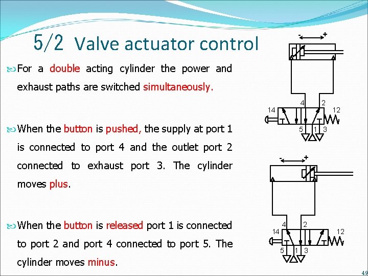
- 5/2 Valve actuator control + For a double acting cylinder the power and exhaust paths are switched simultaneously. 14 When the button is pushed, the supply at port 1 4 2 5 1 3 12 is connected to port 4 and the outlet port 2 connected to exhaust port 3. The cylinder - + moves plus. When the button is released port 1 is connected to port 2 and port 4 connected to port 5. The 14 4 2 5 1 3 12 cylinder moves minus. 49
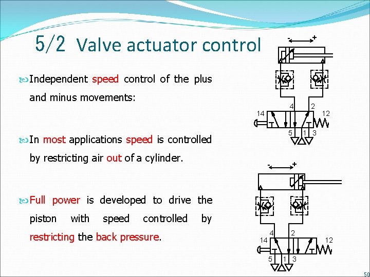
5/2 Valve actuator control - + Independent speed control of the plus and minus movements: 14 In most applications speed is controlled by restricting air out of a cylinder. - 4 2 5 1 3 12 + Full power is developed to drive the piston with speed controlled restricting the back pressure. by 14 4 2 5 1 3 12 50
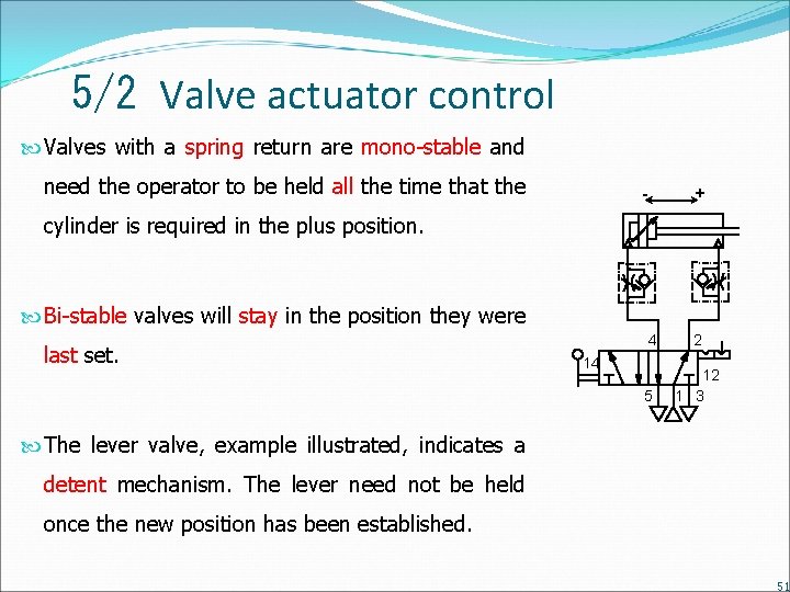
5/2 Valve actuator control Valves with a spring return are mono-stable and need the operator to be held all the time that the - + cylinder is required in the plus position. Bi-stable valves will stay in the position they were last set. 4 2 5 12 1 3 14 The lever valve, example illustrated, indicates a detent mechanism. The lever need not be held once the new position has been established. 51
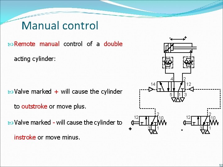
Manual control - Remote manual control of a double + acting cylinder: 4 2 14 12 Valve marked + will cause the cylinder 5 1 3 to outstroke or move plus. Valve marked - will cause the cylinder to 2 10 12 + 3 1 2 10 12 - 3 1 instroke or move minus. 52
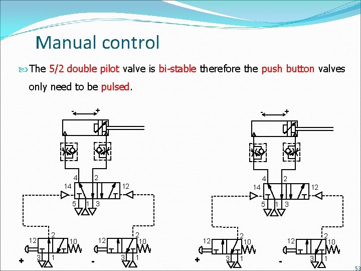
Manual control The 5/2 double pilot valve is bi-stable therefore the push button valves only need to be pulsed. - + 4 2 14 + 3 2 1 - 12 5 2 10 12 3 2 14 1 3 10 + 4 12 5 12 - 1 2 10 12 + 1 3 3 1 2 10 12 - 3 1 53
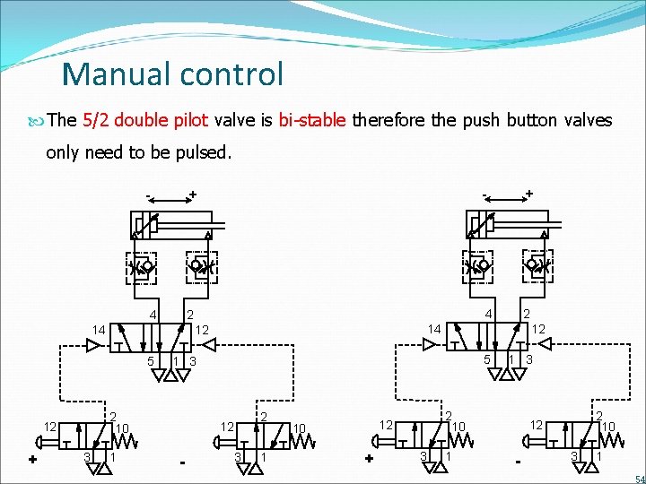
Manual control The 5/2 double pilot valve is bi-stable therefore the push button valves only need to be pulsed. - 4 + 3 1 12 5 1 3 2 10 2 12 - 2 14 12 5 + 4 2 14 12 - + 3 1 2 10 12 10 + 1 3 3 1 2 10 12 - 3 1 54
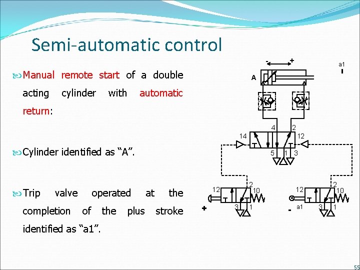
Semi-automatic control - Manual remote start of a double acting cylinder with + a 1 A automatic return: 4 2 14 12 Cylinder identified as “A”. Trip valve completion operated of the plus 5 at stroke 2 10 12 the + 1 3 3 1 2 10 12 - a 1 3 1 identified as “a 1”. 55
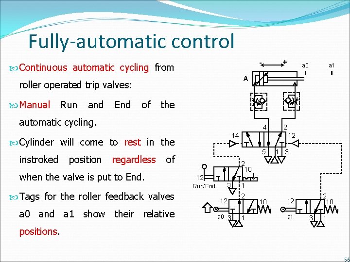
Fully-automatic control - Continuous automatic cycling from Run and End of 4 14 Cylinder will come to rest in the position a 1 the automatic cycling. instroked a 0 A roller operated trip valves: Manual + regardless when the valve is put to End. a 0 and a 1 show their relative 1 3 2 10 12 Run/End Tags for the roller feedback valves 12 5 of 2 3 12 a 0 3 1 2 1 10 2 10 12 a 1 3 1 positions. 56
Sequential control 57
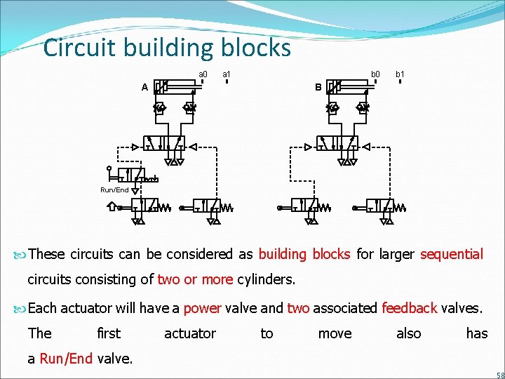
Circuit building blocks a 0 a 1 b 0 A b 1 B Run/End These circuits can be considered as building blocks for larger sequential circuits consisting of two or more cylinders. Each actuator will have a power valve and two associated feedback valves. The first actuator to move also has a Run/End valve. 58
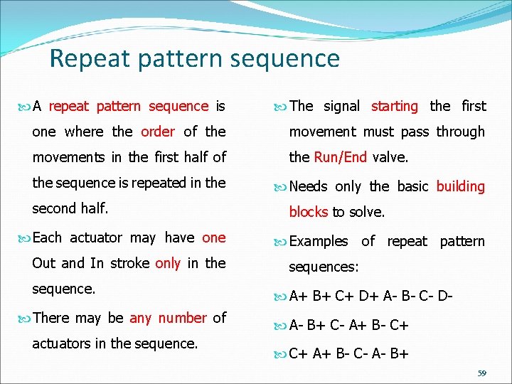
Repeat pattern sequence A repeat pattern sequence is The signal starting the first one where the order of the movement must pass through movements in the first half of the Run/End valve. the sequence is repeated in the second half. Each actuator may have one Out and In stroke only in the sequence. There may be any number of actuators in the sequence. Needs only the basic building blocks to solve. Examples of repeat pattern sequences: A+ B+ C+ D+ A- B- C- D A- B+ C- A+ B- C+ A+ B- C- A- B+ 59
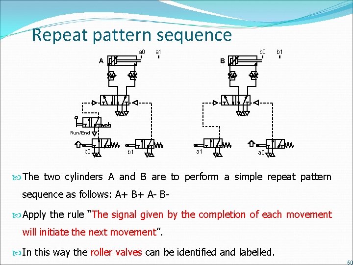
Repeat pattern sequence a 0 a 1 b 0 A b 1 B Run/End b 0 b 1 a 0 The two cylinders A and B are to perform a simple repeat pattern sequence as follows: A+ B+ A- B Apply the rule “The signal given by the completion of each movement will initiate the next movement”. In this way the roller valves can be identified and labelled. 60
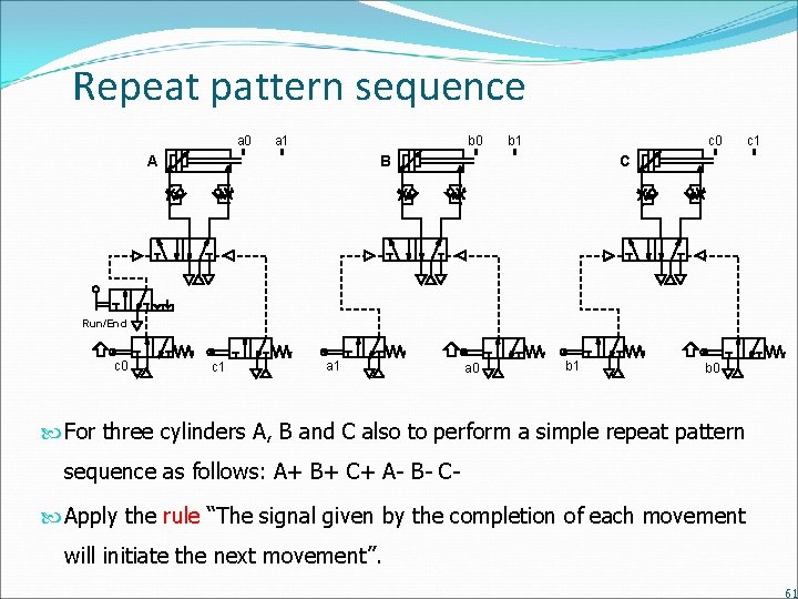
Repeat pattern sequence a 0 a 1 b 0 A b 1 c 0 B c 1 C Run/End c 0 c 1 a 0 b 1 b 0 For three cylinders A, B and C also to perform a simple repeat pattern sequence as follows: A+ B+ C+ A- B- C Apply the rule “The signal given by the completion of each movement will initiate the next movement”. 61
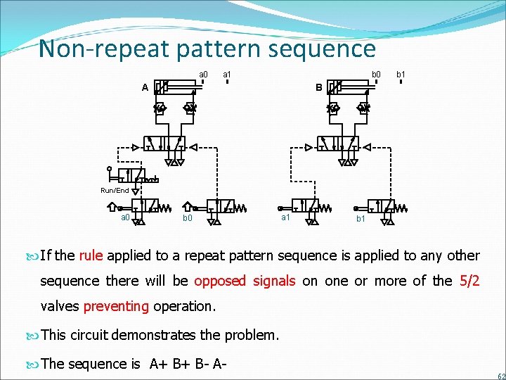
Non-repeat pattern sequence a 0 a 1 b 0 A b 1 B Run/End a 0 b 0 a 1 b 1 If the rule applied to a repeat pattern sequence is applied to any other sequence there will be opposed signals on one or more of the 5/2 valves preventing operation. This circuit demonstrates the problem. The sequence is A+ B+ B- A 62
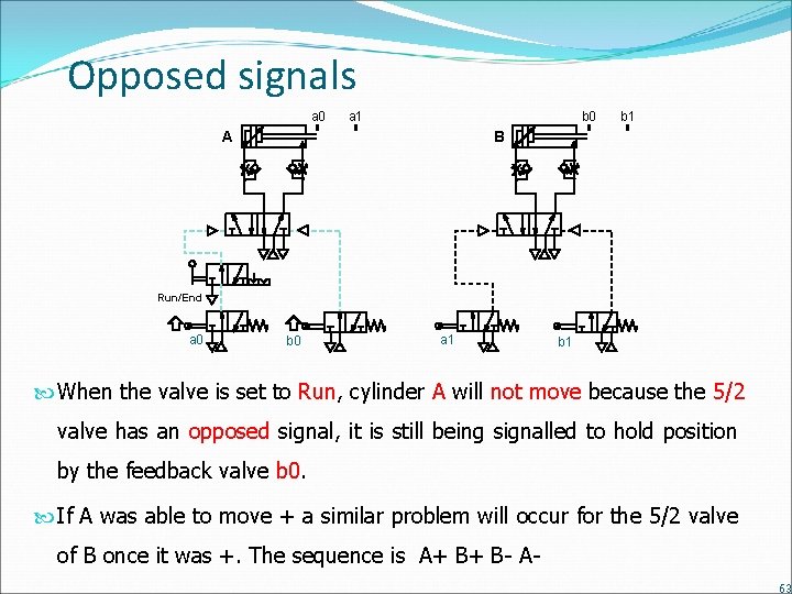
Opposed signals a 0 a 1 b 0 A b 1 B Run/End a 0 b 0 a 1 b 1 When the valve is set to Run, cylinder A will not move because the 5/2 valve has an opposed signal, it is still being signalled to hold position by the feedback valve b 0. If A was able to move + a similar problem will occur for the 5/2 valve of B once it was +. The sequence is A+ B+ B- A 63
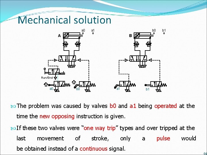
Mechanical solution a 0 a 1 b 0 A b 1 B Run/End a 0 a 1 b 0 b 1 The problem was caused by valves b 0 and a 1 being operated at the time the new opposing instruction is given. If these two valves were “one way trip” types and over tripped at the last movement of stroke, only be obtained instead of a continuous signal. a pulse would 64
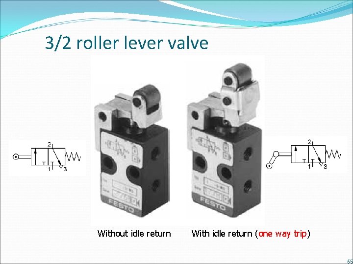
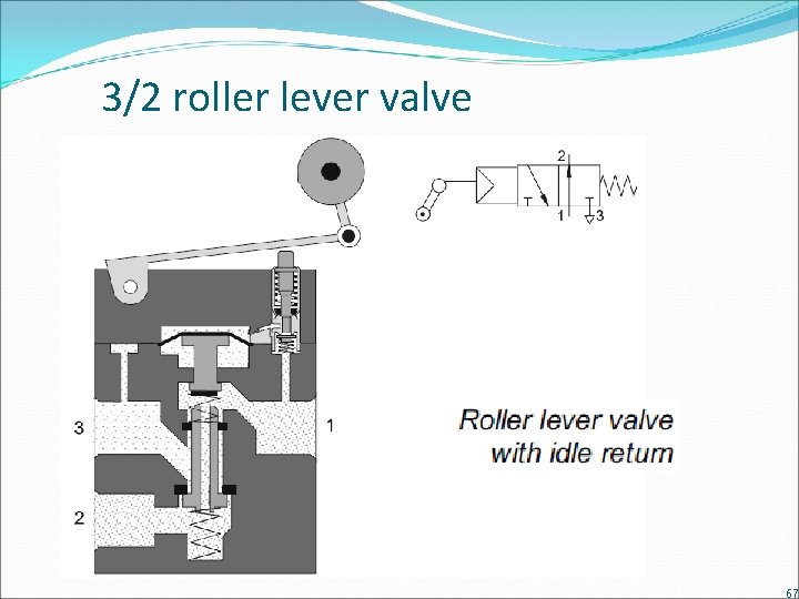
3/2 roller lever valve Without idle return With idle return (one way trip) 65
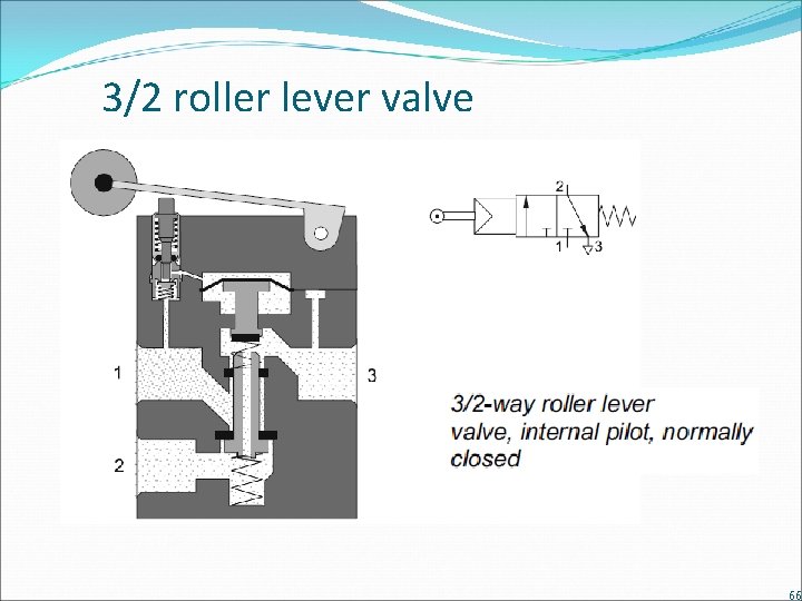
3/2 roller lever valve 66
3/2 roller lever valve 67
Sequence solution methods The main solutions to solving sequences are: Cascade (pneumatic) Shift register (pneumatic) Electro-pneumatic PLC (Programmable controller) logic Cascade circuits provide a standard method of solving any sequence. It uses a minimum of additional logic hardware (one logic valve per group of sequential steps). Shift register circuits are similar to cascade but use one logic valve for every step. Electro-pneumatic circuits use solenoid valves and electromechanical relays. PLC: the standard solution for medium to complex sequential systems (except where electrical equipment cannot be used). 68
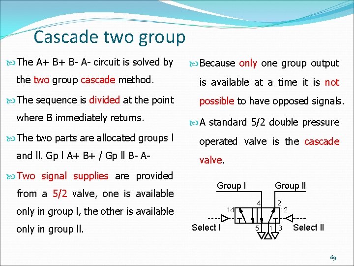
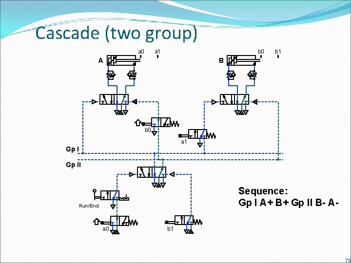
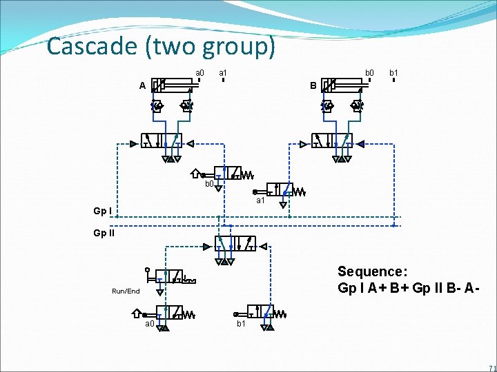
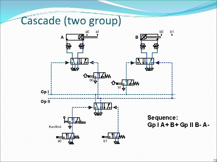
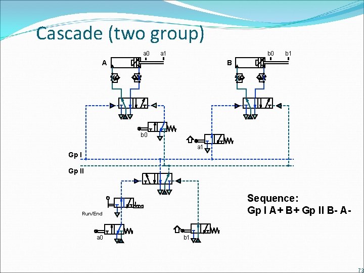
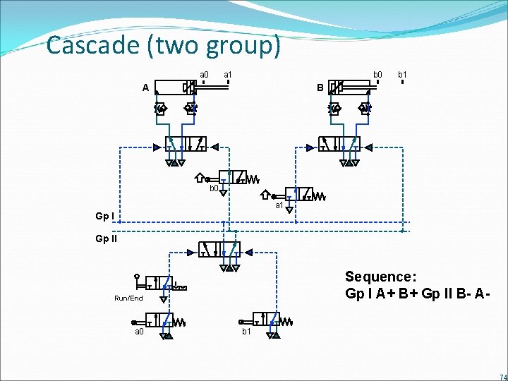
Cascade two group The A+ B+ B- A- circuit is solved by the two group cascade method. The sequence is divided at the point where B immediately returns. The two parts are allocated groups l and ll. Gp l A+ B+ / Gp ll B- A Two signal supplies are provided from a 5/2 valve, one is available Because only one group output is available at a time it is not possible to have opposed signals. A standard 5/2 double pressure operated valve is the cascade valve. Group l only in group l, the other is available only in group ll. 14 Select l Group ll 4 5 2 12 1 3 Select ll 69
Cascade (two group) a 0 a 1 b 0 A b 1 B b 0 a 1 Gp ll Sequence: Gp l A+ B+ Gp ll B- A- Run/End a 0 b 1 70
Cascade (two group) a 0 a 1 b 0 A b 1 B b 0 a 1 Gp ll Sequence: Gp l A+ B+ Gp ll B- A- Run/End a 0 b 1 71
Cascade (two group) a 0 a 1 b 0 A b 1 B b 0 a 1 Gp ll Sequence: Gp l A+ B+ Gp ll B- A- Run/End a 0 b 1 72
Cascade (two group) a 0 a 1 b 0 A b 1 B b 0 a 1 Gp ll Sequence: Gp l A+ B+ Gp ll B- A- Run/End a 0 b 1 73
Cascade (two group) a 0 a 1 b 0 A b 1 B b 0 a 1 Gp ll Sequence: Gp l A+ B+ Gp ll B- A- Run/End a 0 b 1 74
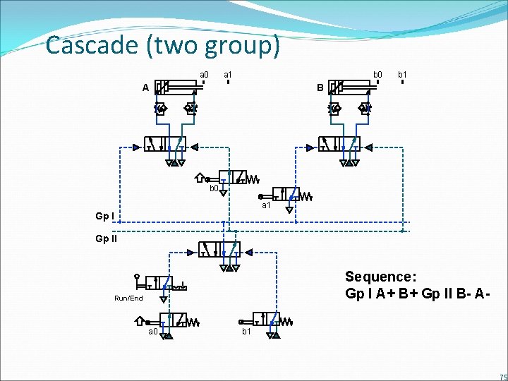
Cascade (two group) a 0 a 1 b 0 A b 1 B b 0 a 1 Gp ll Sequence: Gp l A+ B+ Gp ll B- A- Run/End a 0 b 1 75
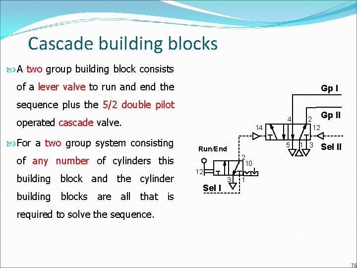
Cascade building blocks A two group building block consists of a lever valve to run and end the Gp l sequence plus the 5/2 double pilot 4 operated cascade valve. For a two group system consisting 14 building blocks are all that is 1 3 Sel ll 2 10 of any number of cylinders this building block and the cylinder 12 5 Run/End Gp ll 2 12 Sel l 3 1 required to solve the sequence. 76
Cascade rules Interconnect the blocks as follows: The first function in each group Divide the sequence in to groups. is signalled directly by that group supply. Always start a sequence with the The last trip valve operated in Run/End valve selecting group l each group is supplied with main supply air and selects the next e. g. group. R/E | A+ B+ | B- C+ | C- A The remaining trip valves are supplied with air from their Select the cylinder building blocks. respective groups and initiate the next function. Select the cascade building block. The “run/end” valve will control the signal from the last trip valve to be operated. Establish the correct sequence 77
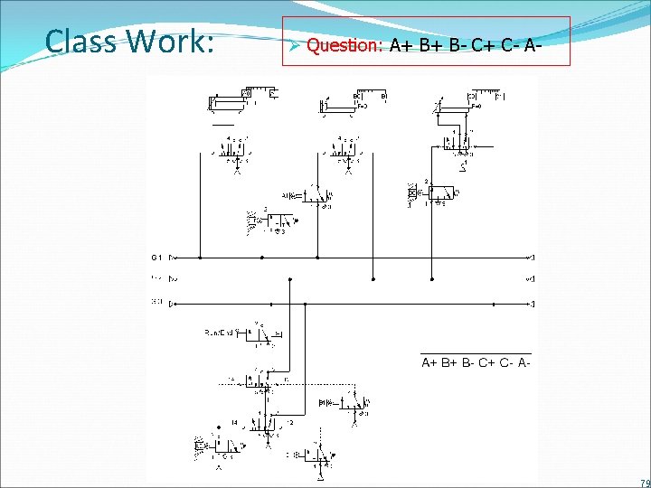
Home Work: Question 1: A+ B+ C+ A- B- C- Question 2: A+ B+ C+ C- B- A- Question 3: A+ A- B+ C+ C- B- 78
Class Work: Ø Question: A+ B+ B- C+ C- A- 79
Logic functions & Feedback methods 80
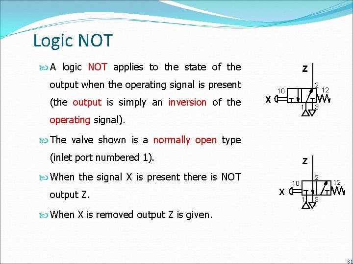
Logic NOT A logic NOT applies to the state of the Z output when the operating signal is present (the output is simply an inversion of the X 2 10 1 12 3 operating signal). The valve shown is a normally open type (inlet port numbered 1). Z When the signal X is present there is NOT output Z. X 2 10 1 12 3 When X is removed output Z is given. 81
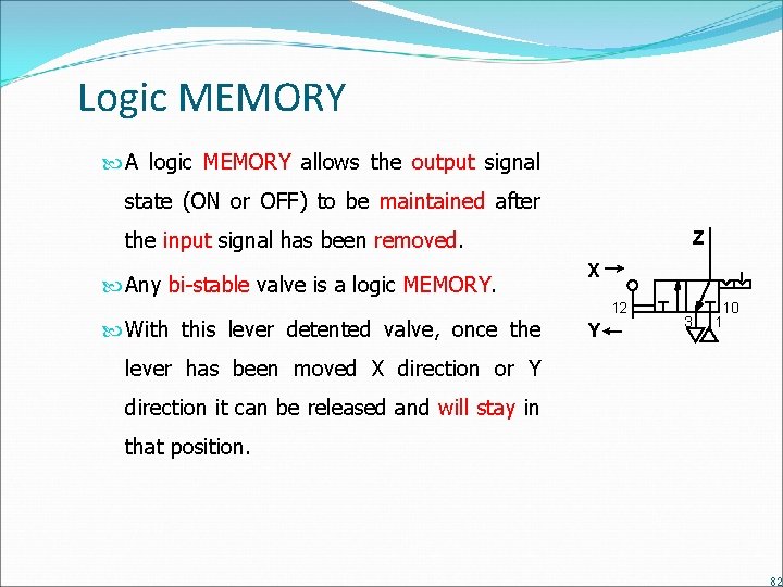
Logic MEMORY A logic MEMORY allows the output signal state (ON or OFF) to be maintained after the input signal has been removed. Any bi-stable valve is a logic MEMORY. With this lever detented valve, once the Z X 12 Y 3 10 1 lever has been moved X direction or Y direction it can be released and will stay in that position. 82
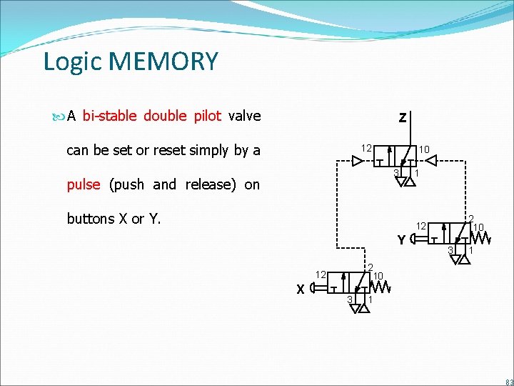
Logic MEMORY A bi-stable double pilot valve Z can be set or reset simply by a 12 10 3 pulse (push and release) on buttons X or Y. 1 2 10 12 Y 1 2 10 12 X 3 3 1 83
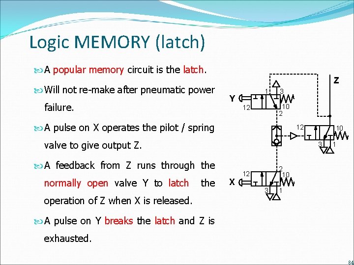
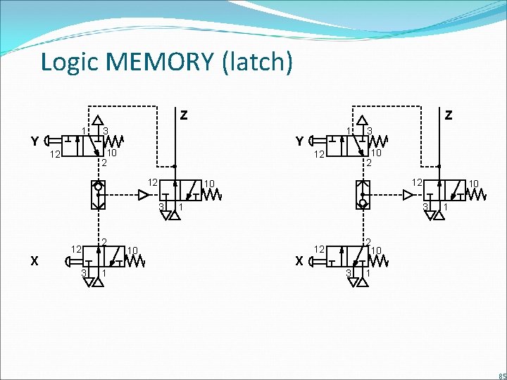
Logic MEMORY (latch) A popular memory circuit is the latch. Will not re-make after pneumatic power failure. Z Y 1 3 10 2 12 A pulse on X operates the pilot / spring 12 valve to give output Z. 3 A feedback from Z runs through the normally open valve Y to latch 10 the operation of Z when X is released. X 1 2 10 12 3 1 A pulse on Y breaks the latch and Z is exhausted. 84
Logic MEMORY (latch) Z Y 1 3 Y 10 2 12 12 12 3 2 1 10 1 3 10 2 12 12 10 3 X Z 1 10 3 X 1 2 10 12 3 1 85
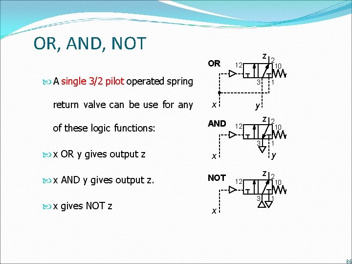
OR, AND, NOT OR z 12 A single 3/2 pilot operated spring return valve can be use for any of these logic functions: 3 x AND 1 y z 12 3 x OR y gives output z x AND y gives output z. x gives NOT z 2 10 1 y x NOT 2 10 z 12 3 2 10 1 x 86
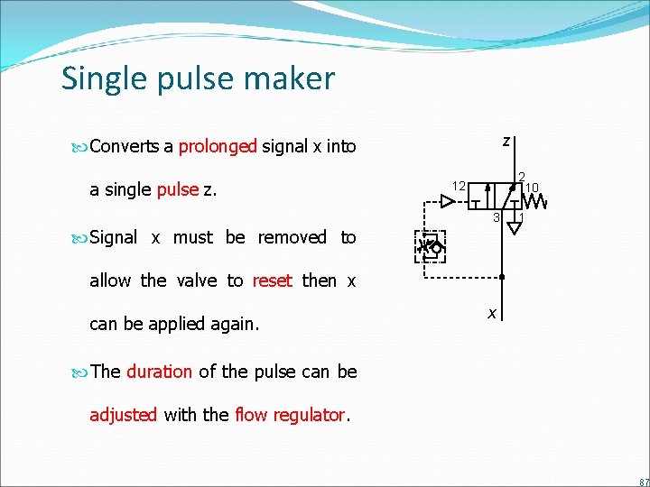
Single pulse maker z Converts a prolonged signal x into a single pulse z. 2 10 12 3 1 Signal x must be removed to allow the valve to reset then x can be applied again. x The duration of the pulse can be adjusted with the flow regulator. 87
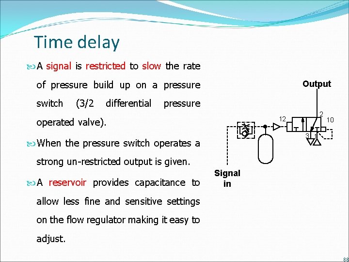
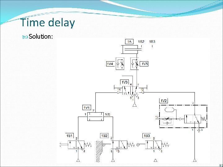
Time delay A signal is restricted to slow the rate of pressure build up on a pressure switch (3/2 differential Output pressure 2 12 operated valve). 10 3 1 When the pressure switch operates a strong un-restricted output is given. A reservoir provides capacitance to Signal in allow less fine and sensitive settings on the flow regulator making it easy to adjust. 88
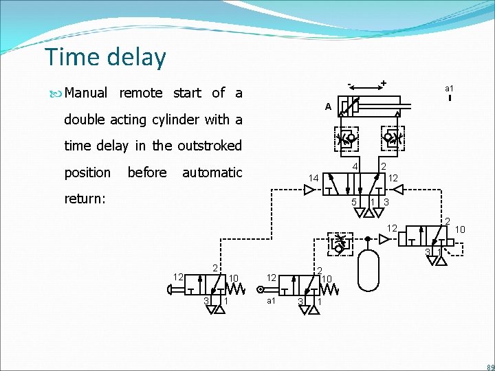
Time delay - Manual remote start of a + a 1 A double acting cylinder with a time delay in the outstroked position before 4 automatic 14 return: 2 12 5 1 3 2 12 10 3 1 2 10 12 a 1 3 1 89
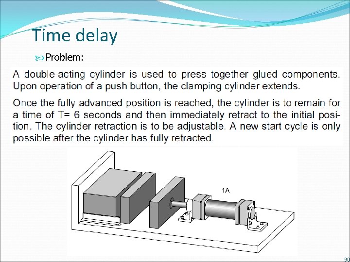
Time delay Problem: 90
Time delay Solution: 91
- Slides: 92