
HYDRAULICS PNEUMATICS Actuators Presented by Dr Abootorabi 1
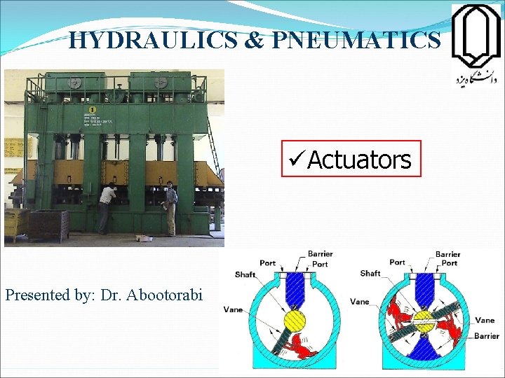
HYDRAULICS & PNEUMATICS üActuators Presented by: Dr. Abootorabi 1
Hydraulic Cylinders Actuators are the components used in a hydraulic system to provide power to a required work location. Cylinders are the hydraulic system components that convert fluid pressure and flow into linear mechanical force and movement. 2
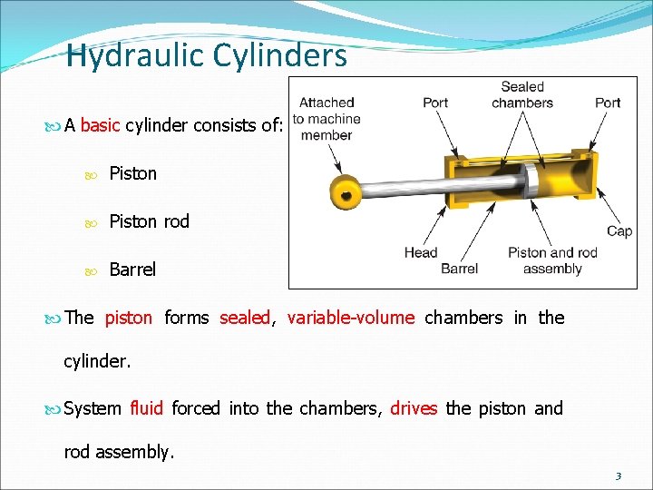
Hydraulic Cylinders A basic cylinder consists of: Piston rod Barrel The piston forms sealed, variable-volume chambers in the cylinder. System fluid forced into the chambers, drives the piston and rod assembly. 3
Hydraulic Cylinders Seals prevent leakage between: Piston and cylinder barrel Piston rod and head Barrel and its end pieces Wiper seal, or scraper, prevents dirt and water from entering the cylinder during rod retraction. 4
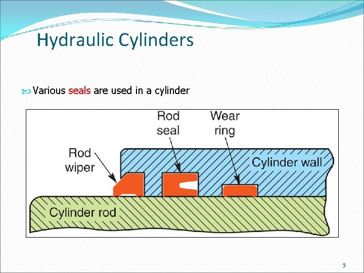
Hydraulic Cylinders Various seals are used in a cylinder 5
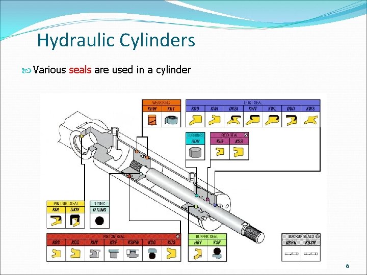
Hydraulic Cylinders Various seals are used in a cylinder 6
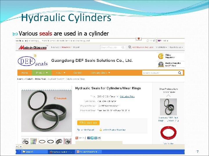
Hydraulic Cylinders Various seals are used in a cylinder 7
Hydraulic Cylinders Various seals are used in a cylinder 8
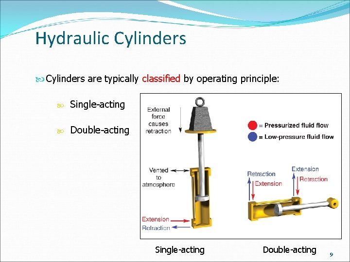
Hydraulic Cylinders are typically classified by operating principle: Single-acting Double-acting 9
Hydraulic Cylinders Single-acting cylinder exert force either on extension or retraction: They require an outside force to complete the second motion (either by a spring or by the weight load). Double-acting cylinder generate force during both extension and retraction: Directional control valve alternately directs fluid to opposite sides of the piston Force output varies between extension and retraction 10
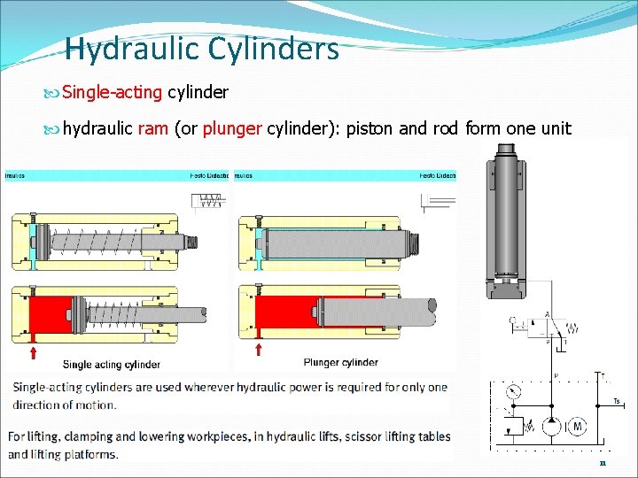
Hydraulic Cylinders Single-acting cylinder hydraulic ram (or plunger cylinder): piston and rod form one unit 11
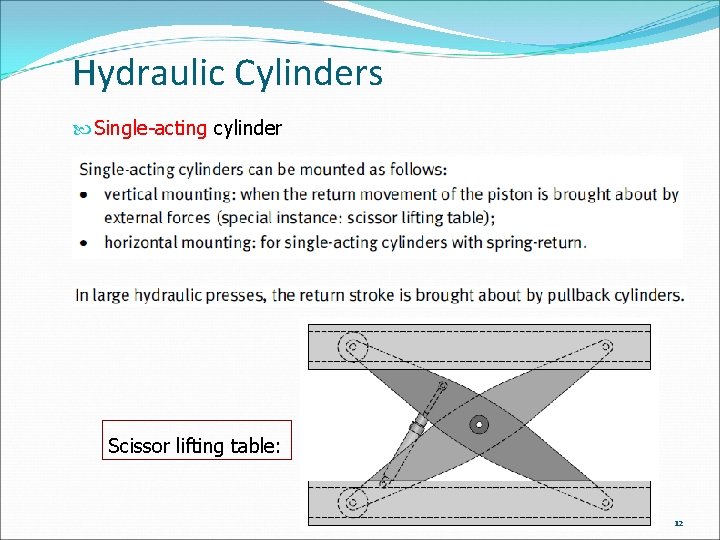
Hydraulic Cylinders Single-acting cylinder Scissor lifting table: 12
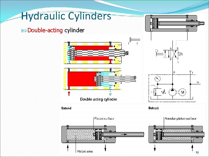
Hydraulic Cylinders Double-acting cylinder 13
Hydraulic Cylinders Double-acting cylinder 14
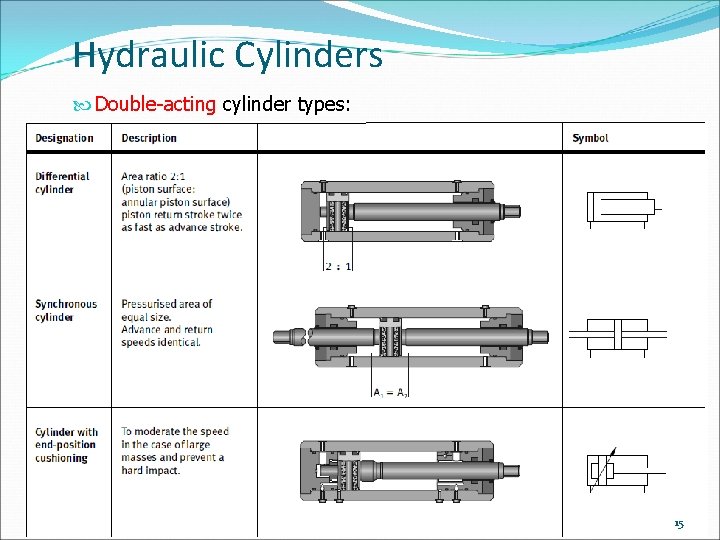
Hydraulic Cylinders Double-acting cylinder types: 15
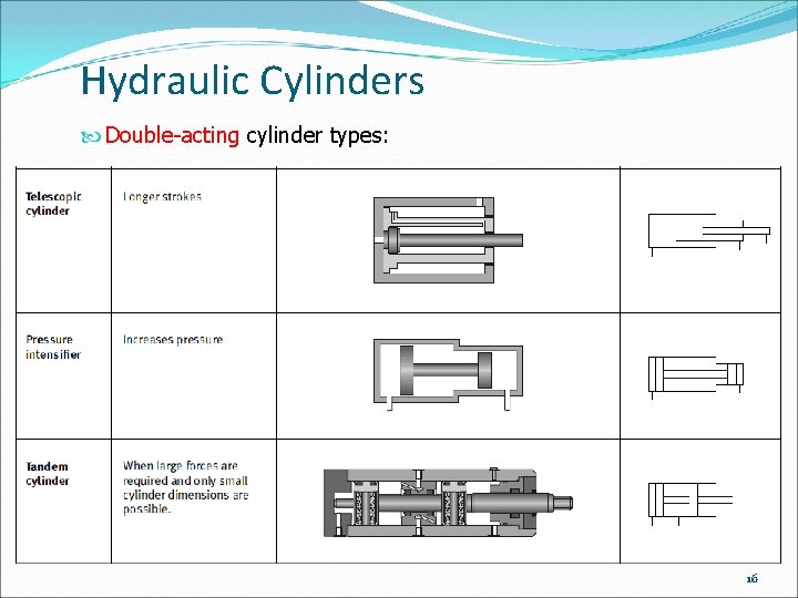
Hydraulic Cylinders Double-acting cylinder types: 16
Hydraulic Cylinders Double-acting cylinder types: 17
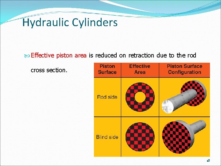
Hydraulic Cylinders Effective piston area is reduced on retraction due to the rod cross section. 18
Hydraulic Cylinders Telescoping cylinders are available for applications requiring long extension distances: Rod is made up of several tubes of varying size nested inside of the barrel Each tube extends, producing a rod longer than the cylinder barrel Typical example is the actuator that raises the box on a dump truck 19
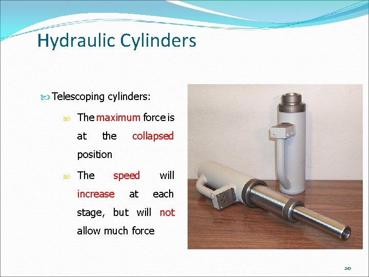
Hydraulic Cylinders Telescoping cylinders: The maximum force is at the collapsed position The speed increase at will each stage, but will not allow much force 20
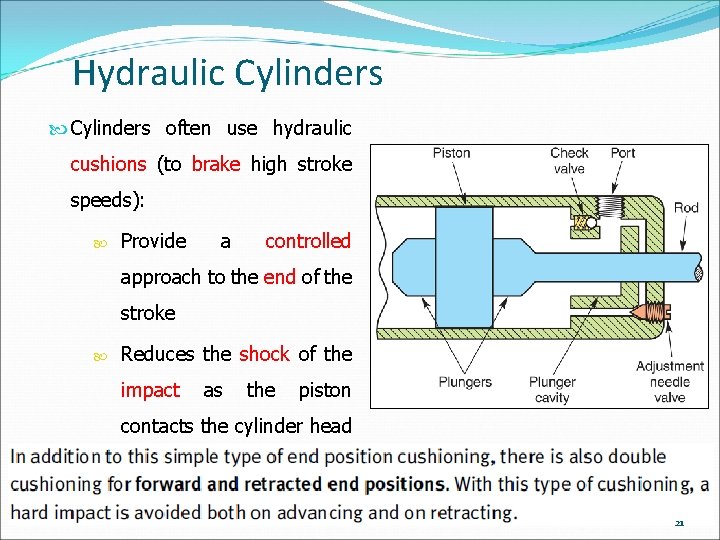
Hydraulic Cylinders often use hydraulic cushions (to brake high stroke speeds): Provide a controlled approach to the end of the stroke Reduces the shock of the impact as the piston contacts the cylinder head 21
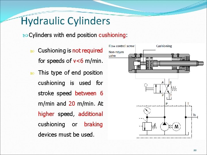
Hydraulic Cylinders with end position cushioning: Cushioning is not required for speeds of v<6 m/min. This type of end position cushioning is used for stroke speed between 6 m/min and 20 m/min. At higher speed, additional cushioning or braking devices must be used. 22
Hydraulic Cylinders A variety of mounting configurations are used to attach the cylinder body and rod end to machinery: Fixed centerline Fixed noncenterline Pivoting centerline Expected cylinder loading is the major factor in the selection of the mounting style. 23
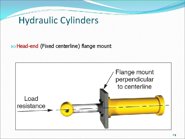
Hydraulic Cylinders Head-end (Fixed centerline) flange mount 24
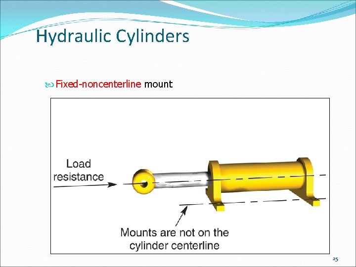
Hydraulic Cylinders Fixed-noncenterline mount 25
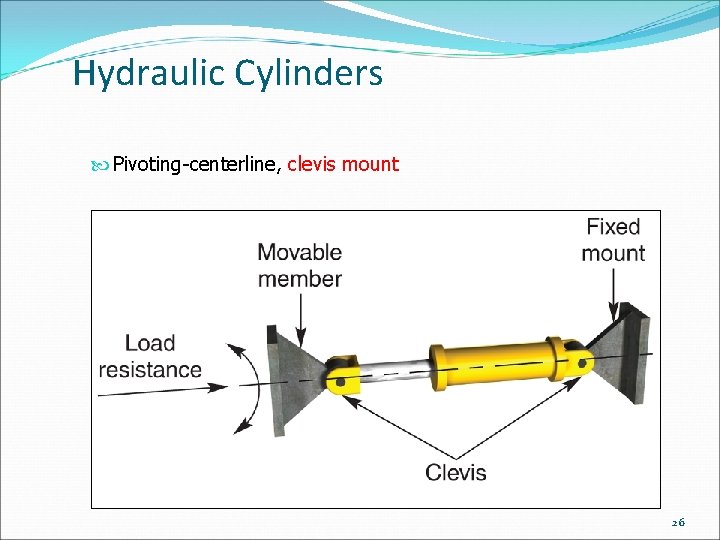
Hydraulic Cylinders Pivoting-centerline, clevis mount 26
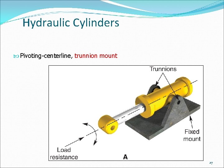
Hydraulic Cylinders Pivoting-centerline, trunnion mount 27
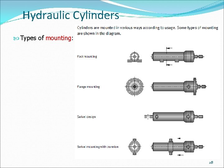
Hydraulic Cylinders Types of mounting: 28
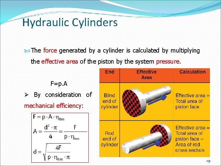
Hydraulic Cylinders The force generated by a cylinder is calculated by multiplying the effective area of the piston by the system pressure. F=p. A Ø By consideration of mechanical efficiency: 29
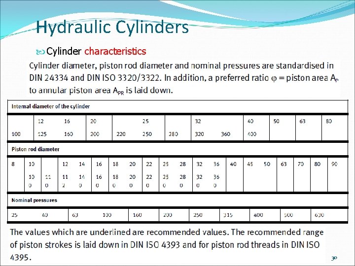
Hydraulic Cylinders Cylinder characteristics 30
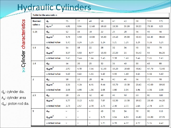
Cylinder characteristics Hydraulic Cylinders dp: cylinder dia. Ap: cylinder area d. ST: piston rod dia. 31
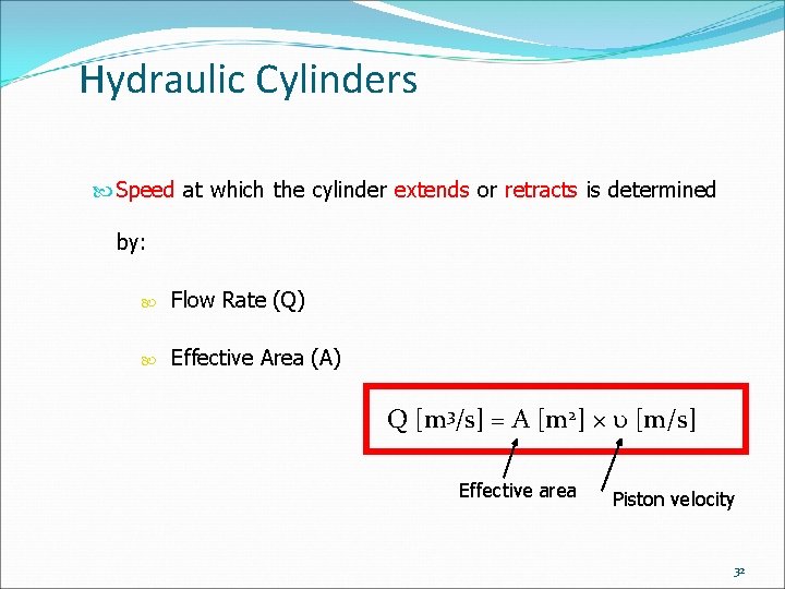
Hydraulic Cylinders Speed at which the cylinder extends or retracts is determined by: Flow Rate (Q) Effective Area (A) Q [m 3/s] = A [m 2] × [m/s] Effective area Piston velocity 32
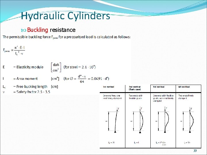
Hydraulic Cylinders Buckling resistance 33
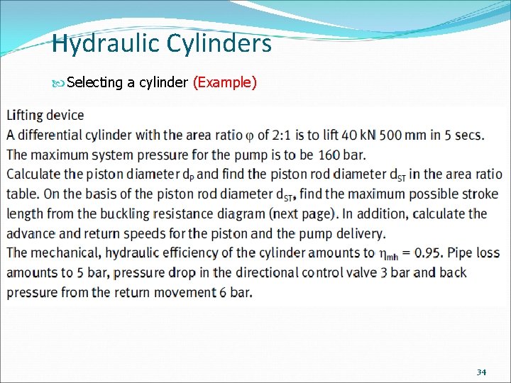
Hydraulic Cylinders Selecting a cylinder (Example) 34
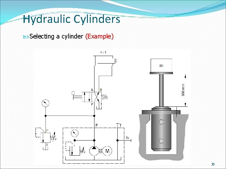
Hydraulic Cylinders Selecting a cylinder (Example) 35
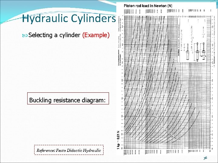
Hydraulic Cylinders Selecting a cylinder (Example) Buckling resistance diagram: Reference: Festo Didactic Hydraulic 36
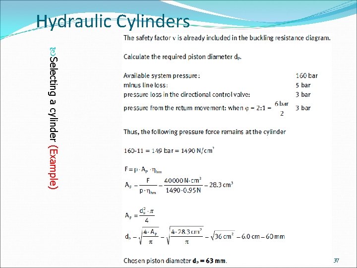
Hydraulic Cylinders Selecting a cylinder (Example) 37
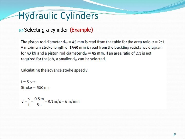
Hydraulic Cylinders Selecting a cylinder (Example) 38
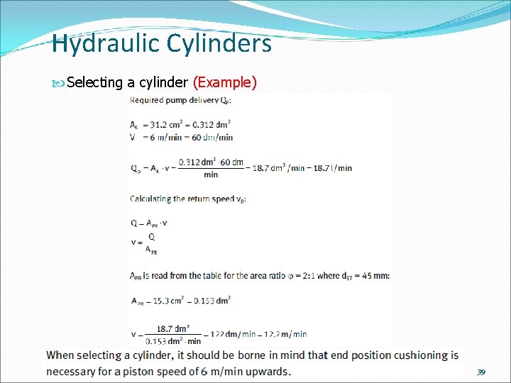
Hydraulic Cylinders Selecting a cylinder (Example) 39
Hydraulic Cylinders 40
Hydraulic Cylinders Hydraulic cylinder manufacturers provide detailed specifications and basic factors such as: Bore Stroke Pressure rating Other details, such as service rating, rod end configurations, and dimensions 41
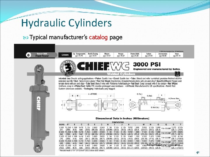
Hydraulic Cylinders Typical manufacturer’s catalog page Bailey International Corporation 42
Limited-Rotation Hydraulic Actuators Limited-rotation devices (swivel drive) are actuators with an output shaft that typically applies torque through approximately 360° of rotation. Models are available that are limited to less than one revolution, while others may produce several revolutions. 43
Limited-Rotation Hydraulic Actuators Most common designs of limited-rotation actuators are: Rack-and-pinion Vane Helical piston and rod 44
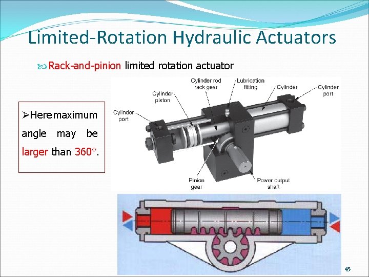
Limited-Rotation Hydraulic Actuators Rack-and-pinion limited rotation actuator ØHere maximum angle may be larger than 360°. 45
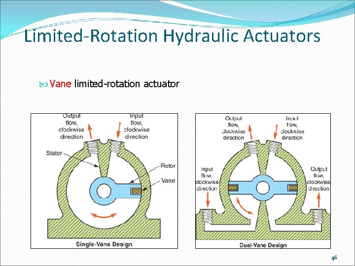
Limited-Rotation Hydraulic Actuators Vane limited-rotation actuator 46
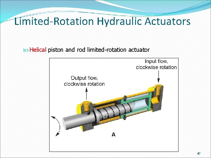
Limited-Rotation Hydraulic Actuators Helical piston and rod limited-rotation actuator 47
Limited-Rotation Hydraulic Actuators Helical piston and rod limited-rotation actuator 48
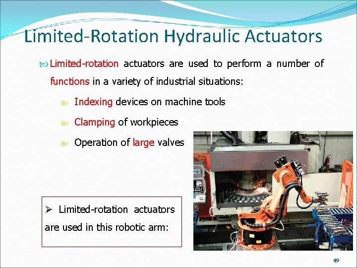
Limited-Rotation Hydraulic Actuators Limited-rotation actuators are used to perform a number of functions in a variety of industrial situations: Indexing devices on machine tools Clamping of workpieces Operation of large valves Ø Limited-rotation actuators are used in this robotic arm: 49
Limited-Rotation Hydraulic Actuators Operation of large valves 50
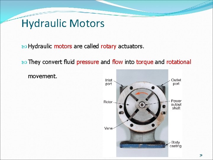
Hydraulic Motors Hydraulic motors are called rotary actuators. They convert fluid pressure and flow into torque and rotational movement. 51
Hydraulic Motors System fluid enters the housing and applies pressure to the rotating internal parts. This, in turn, moves the power output shaft and applies torque to rotate a load. Primary parts that produce the rotating motion in most hydraulic motors are either: Gears Vanes Pistons 52
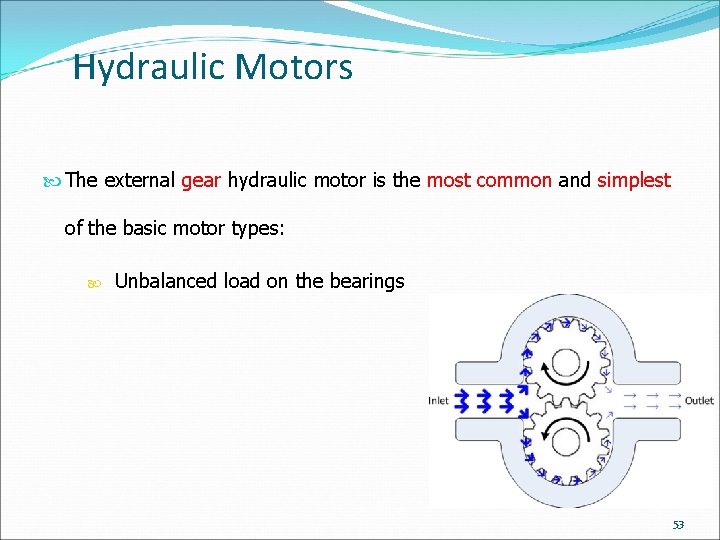
Hydraulic Motors The external gear hydraulic motor is the most common and simplest of the basic motor types: Unbalanced load on the bearings 53
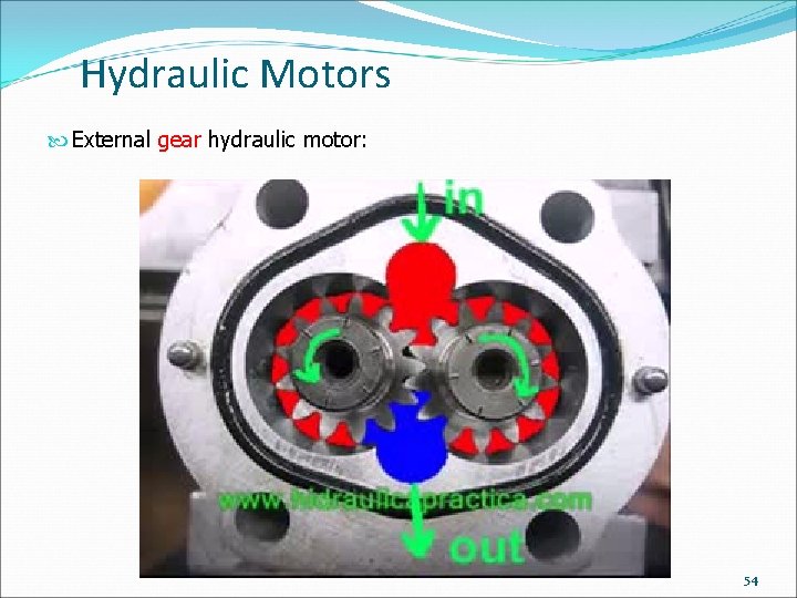
Hydraulic Motors External gear hydraulic motor: 54
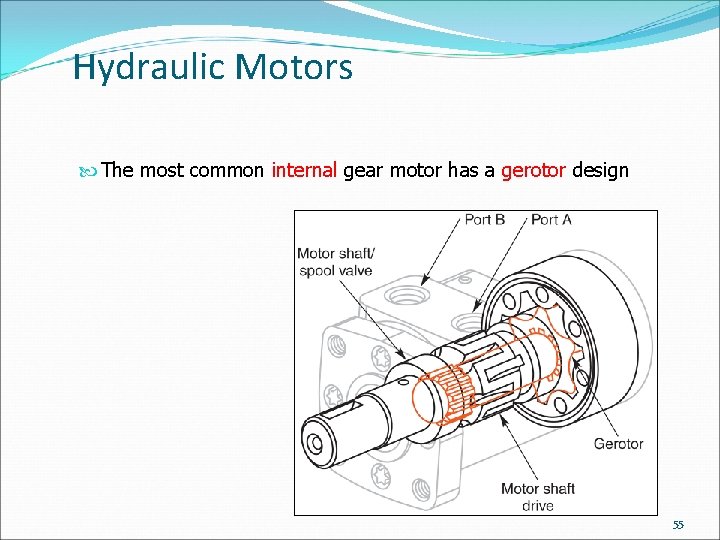
Hydraulic Motors The most common internal gear motor has a gerotor design 55
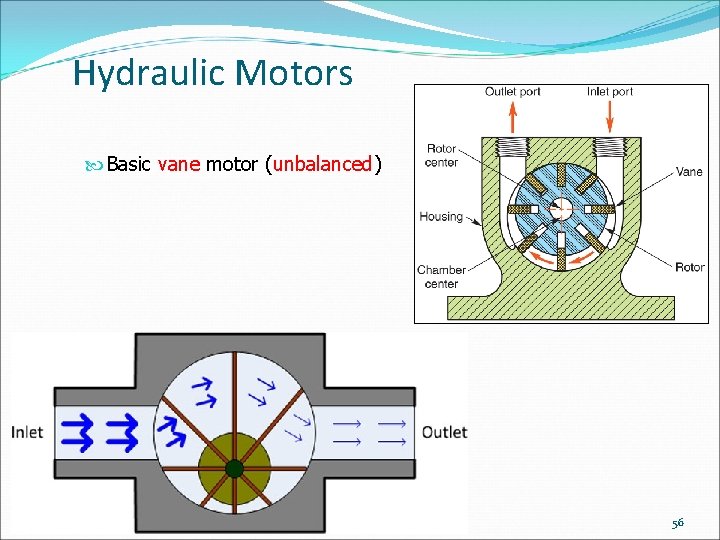
Hydraulic Motors Basic vane motor (unbalanced) 56
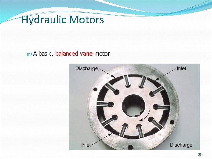
Hydraulic Motors A basic, balanced vane motor 57
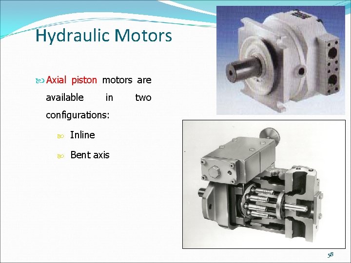
Hydraulic Motors Axial piston motors are available in two configurations: Inline Bent axis 58
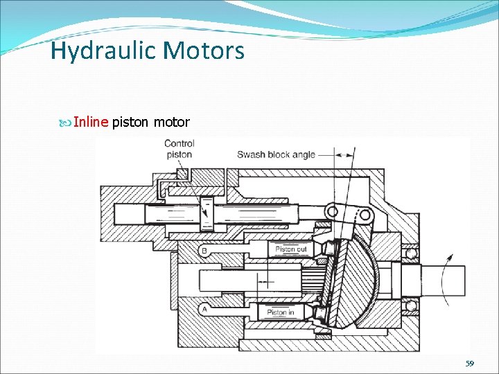
Hydraulic Motors Inline piston motor 59
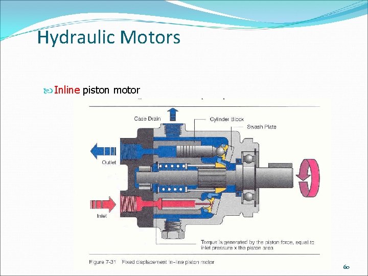
Hydraulic Motors Inline piston motor 60
Hydraulic Motors Inline piston motor 61
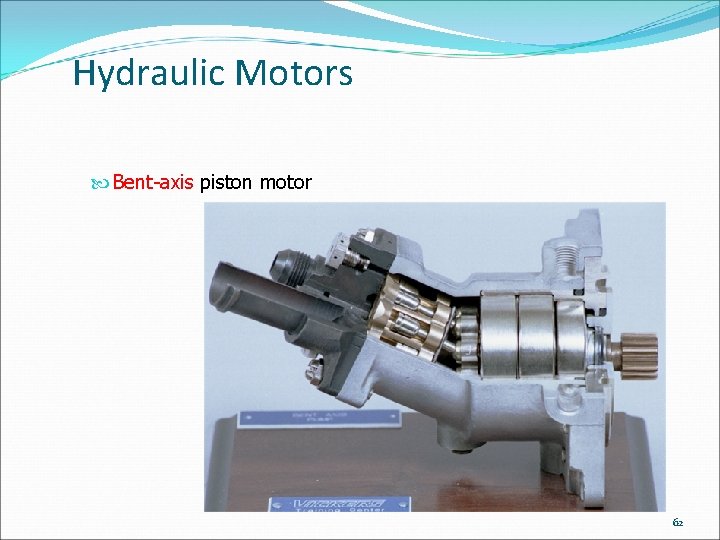
Hydraulic Motors Bent-axis piston motor 62
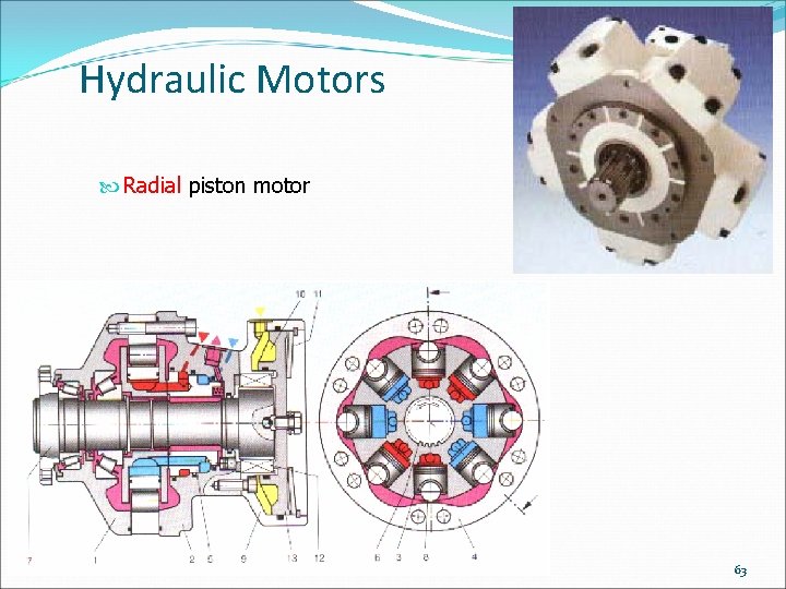
Hydraulic Motors Radial piston motor 63
Hydraulic Motors Radial piston motor 64
Hydraulic Motors Hydraulic motors may be incorporated into circuits using series or parallel connections: Series circuits: total system pressure is determined by adding the loads placed on each unit Parallel circuits: each motor receives full system pressure; loads must be matched or equal flow supplied to each motor if constant speed is desired from each unit 65
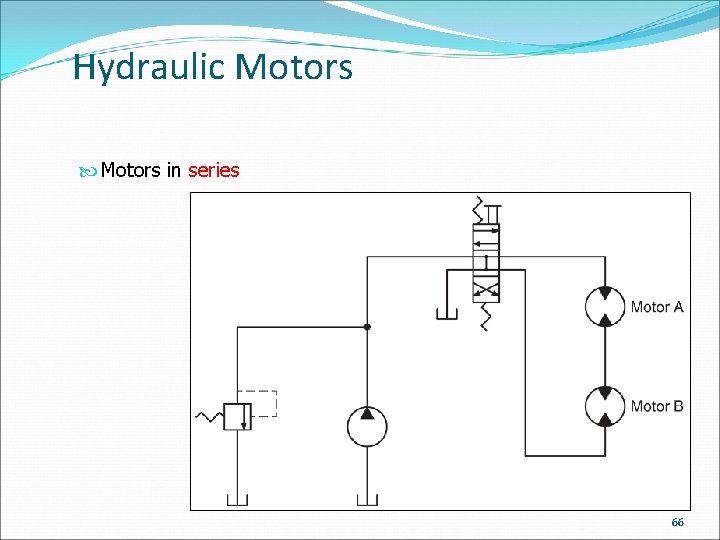
Hydraulic Motors in series 66
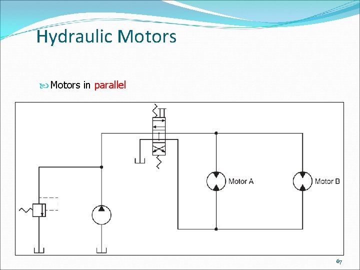
Hydraulic Motors in parallel 67
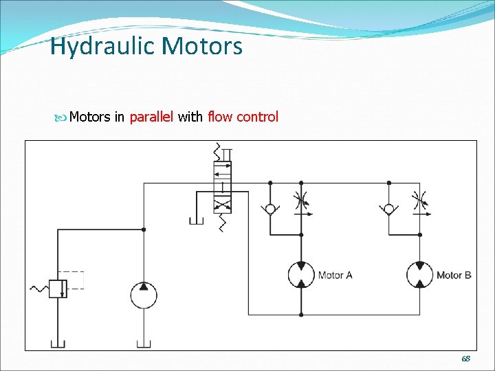
Hydraulic Motors in parallel with flow control 68
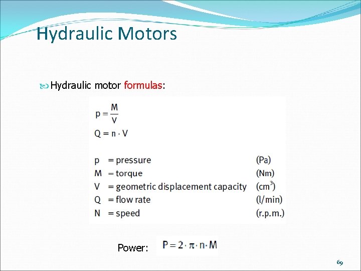
Hydraulic Motors Hydraulic motor formulas: Power: 69

The end. 70
- Slides: 70