Hydraulic Filtration Technology Topics Contamination Basics Contamination Types

Hydraulic Filtration Technology

Topics • • Contamination Basics Contamination Types and Sources Fluid Cleanliness Standards Filter Media Types and Ratings Filter Element Life Filter Housing Selection Fluid Analysis

Contamination Basics

Over 75% of hydraulic and lubrication system failures can be attributed to excessive contamination

Excessive Contamination Causes: • • • Loss of Production Component Replacement Costs Frequent Fluid Replacement Costly Fluid Disposal Increased Overall Maintenance Costs Increased Scrap Rate

Contaminant Damage • • • Orifice Blockage Component Wear Rust or Other Oxidation Chemical Compound Formation Depletion of Additives Biological Growth

Typical Hydraulic Component Clearances Component Microns Anti-friction bearings Vane pump (vane tip to outer ring) Gear pump (gear to side plate) Servo valves (spool to sleeve) Hydrostatic bearings Piston pump (piston to bore) Servo valve flapper wall Actuators Servo valve orifice 0. 5 -1 0. 5 -5 1 -4 1 -25 5 -40 18 -63 50 -250 130 -450

Relative Sizes of Particles Substance Grain of Table Salt Microns Inches 100 . 0039 Human Hair 70 . 0027 Lower Limit of Visibility 40 . 0016 Milled Flour 25 . 0010 Red Blood Cells 8 . 0003 Bacteria 2 . 0001
")
(Magnified 100 x Scale: 1 division = 20 microns)

Contamination Types and Sources


• • Built-In During Manufacture and Assembly Ingested Into System During Operation Added with New Fluid Internally Generated During Operation

Contamination Sources • • Built-In During Manufacture and Assembly Ingested Into System During Operation Added with New Fluid Internally Generated During Operation


Contamination Ingression Rates for Typical Hydraulic Systems Classified by Operating Environment Mobile Equipment 108 - 1010 Per Minute* Manufacturing Plant & Mills 106 - 108 Per Minute* Assemblers & Clean Rooms 105 - 106 Per Minute* *Particle greater than 10 micrometers in size entering the reservoir due to component wear plus external sources.

Particle Contamination Prevention • Filter Air Breather • Correct System Flushing • Replace Worn Actuator Seals • Prevention of Contaminant Ingression During Servicing • New Fluid Filtration

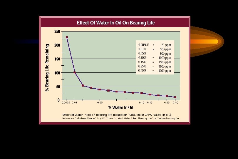
Water Contamination Types • Dissolved Water • Free Water

Typical Saturation Points Fluid Type PPM % Hydraulic Fluid 300 . 03% Lubrication Fluid 400 . 04% Transformer Fluid 50 . 005%


Water Contamination Damage • Corrosion of Metal Surfaces • Accelerated Abrasive Wear • Bearing Fatigue • Fluid Additive Breakdown • Viscosity Variance • Increase in Electrical Conductivity

Water Contamination Sources • Worn Actuator Seals • Reservoir Opening Leaks • Condensation • Heat Exchanger Leakage

Water Contamination Prevention • Absorption • Centrifugation • Vacuum Dehydration

PVS Portable Oil Purifiers Five Standard Models to Choose From • PVS 180 • PVS 600 • PVS 1200 • PVS 1800 • PVS 2700

Fluid Cleanliness Standards
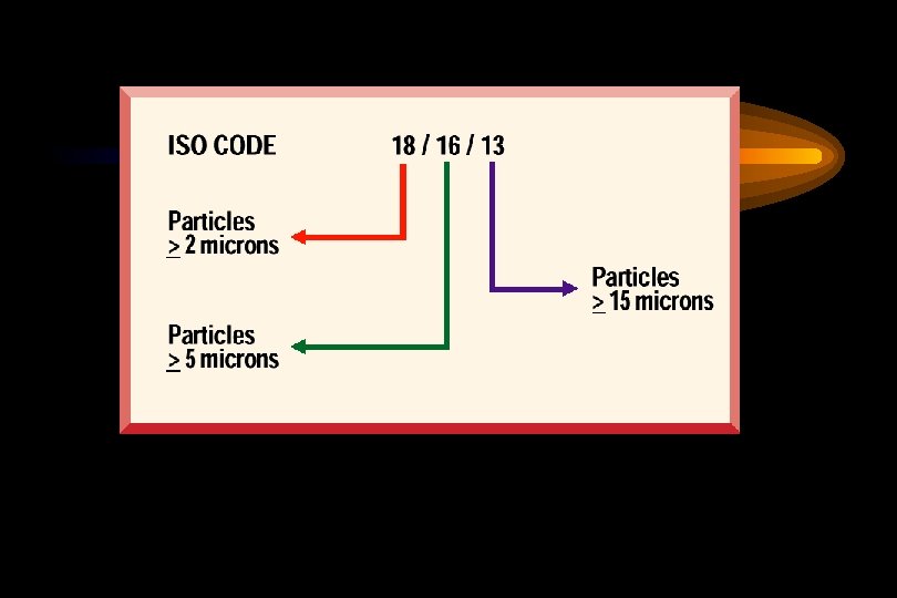

ISO 4406 Chart Range Number 24 23 22 21 20 19 18 17 16 15 14 13 12 11 10 9 8 7 6 Number of Particles per ml More than 80, 000 40, 000 20, 000 10, 000 5, 000 2, 500 1, 300 640 320 160 80 40 20 10 5 2. 5 1. 3. 64. 32 Up to and including 160, 000 80, 000 40, 000 20, 000 10, 000 5, 000 2, 500 1, 300 640 320 160 80 40 20 10 5 2. 5 1. 3. 64

Fluid Cleanliness Level Required for Typical Hydraulic Components ISO Code Servo Control Valves 16/14/11 Vane and Piston Pumps/Motors 18/16/13 Directional & Pressure Control Valves 18/16/13 Gear Pumps/Motors 19/17/14 Flow Control Valves/ Cylinders 20/18/15 New Unused Fluid 20/18/15
")
ISO 16/14/11 fluid (magnification 100 x)
")
ISO 21/19/17 fluid (magnification 100 x)

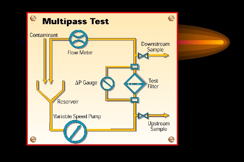
Filter Media Ratings

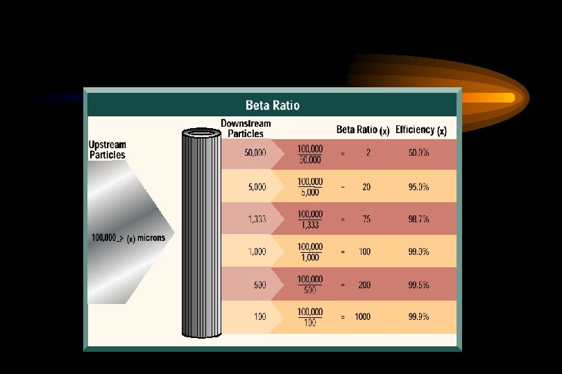
Filter Media Ratings Expressed as a Beta Ratio Indicate a Media’s Particle Removal Efficiency

ßeta Ratio x = “ x” = ß 10 = # of particles upstream # of particles downstream specific particle size 50, 000 10, 000 =5
")
Efficiencyx = ( 1 - 1 ßeta 1 - 1 5 = 80% ) 100
 1. 01 1. 5")
Beta Ratio/Efficiency Table Beta Ratio (at a given particle size) 1. 01 1. 5 2. 0 5. 0 10. 0 20. 0 75. 0 100. 0 200. 0 1000. 0 Capture Efficiency (at same particle size) 1. 0% 9. 0% 33. 3% 50. 0% 80. 0% 95. 0% 98. 7% 99. 0% 99. 5% 99. 9%

Filter Housing Selection

Typical Filter Assembly Features Condition indicator Bypass valve assembly Inlet port Pressure housing Filter element

Filter Selection Criteria • System Pressure • Fluid Flow Rate • Design Options • Media Choice • Bypass Valve Setting

Types and Locations of Filters

• Suction • Pressure • Return • Off-line

Fluid Analysis

Fluid Analysis Methods Patch Test • Visual density comparison • Microscopic examination Portable Particle Counter • Particle size and distribution • Convenient on-site use Laboratory Analysis • • Viscosity and water content Spectrometric analysis Particle count Gravimetric analysis

- Slides: 45