Hydraulic and Pneumatic Circuits Design Objectives After this

Hydraulic and Pneumatic Circuits Design

Objectives After this Lecture the student will be able to: • Identify all the symbols used in hydraulic schematics • Understand various hydraulic circuits • Understand explain hydraulic schematics effectively • Design a hydraulic circuit for performing a desired function • Analyze the function of each hydraulic circuit in an application.

The following considerations must be taken into account: • • Safety of operation • • Performance of the desired function • • Efficiency of operation.

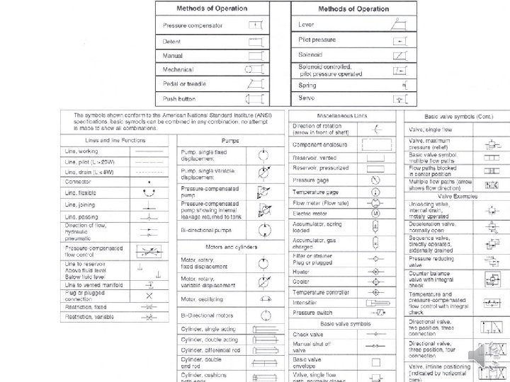
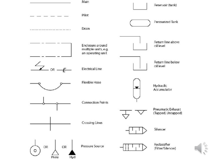
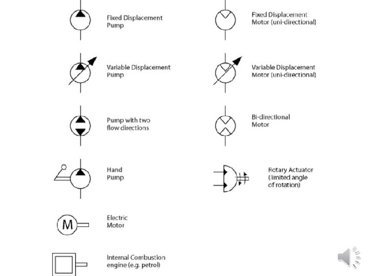
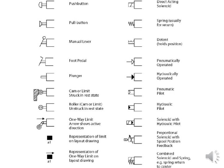
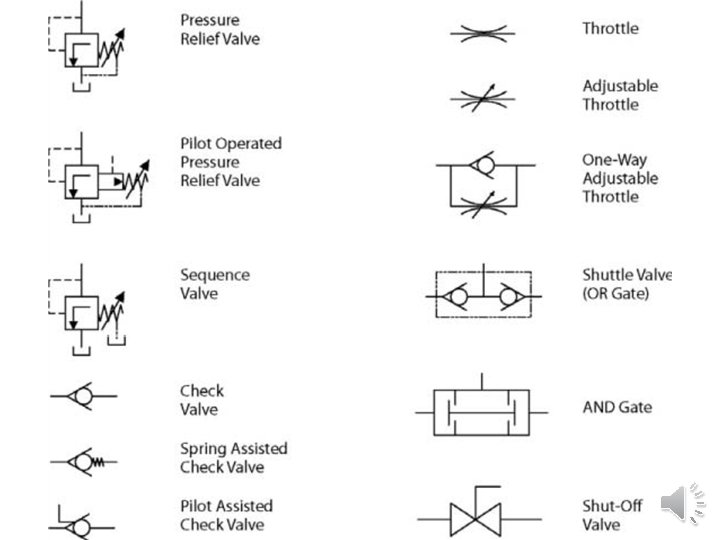
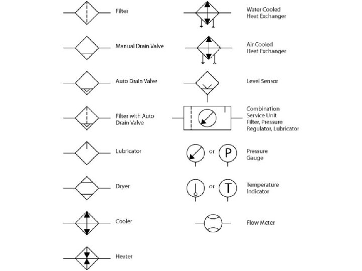
Symbols of hydraulic components • It is very important for a fluid power technician or a designer to have knowledge of each of the hydraulic components and their functions in a hydraulic circuit. Hydraulic circuits are developed by using graphical symbols for all of the components. Therefore it is pertinent to know the symbols of each and every component used in a hydraulic
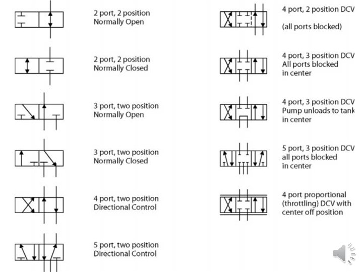

Control of a double acting hydraulic cylinder circuit When the 4 -way valve is in its centered position, the cylinder is hydraulically locked. Also the pump is loaded back to the tank at atmospheric pressure. When the 4 -way valve is actuated into the flow path configuration of the left, the cylinder is extended against its force load (F load) as oil flows from port P through port A. The oil at the rod end of the cylinder is free to flow back into the reservoir through the 4 -way valve from port B through port T. The cylinder will not extend if the oil in the rod end is not allowed to flow back to the reservoir. When the 4 -way valve is actuated in the right envelope configuration, the cylinder retracts, as oil flows from port P through port B. Oil in the blank end is allowed to flow back from A through T. At the end of the stroke, there is no system demand for oil. Therefore the pump flow goes through the relief valve at its set pressure, unless the four-way valve is de activated. The system is protected from cylinder overloads. The check valve prevents the load from retracting the cylinder, while it is being extended using the left envelope flow path configuration

Regenerative circuit • A regenerative circuit used to accelerate the extending speed of the double acting hydraulic cylinder. • In this system, both ends of the hydraulic cylinder are connected in parallel and one of the ports of the 4 -way valve is blocked. The operation of the cylinder during the retraction stroke is the same as that of a regular double acting cylinder.
 II. Control")
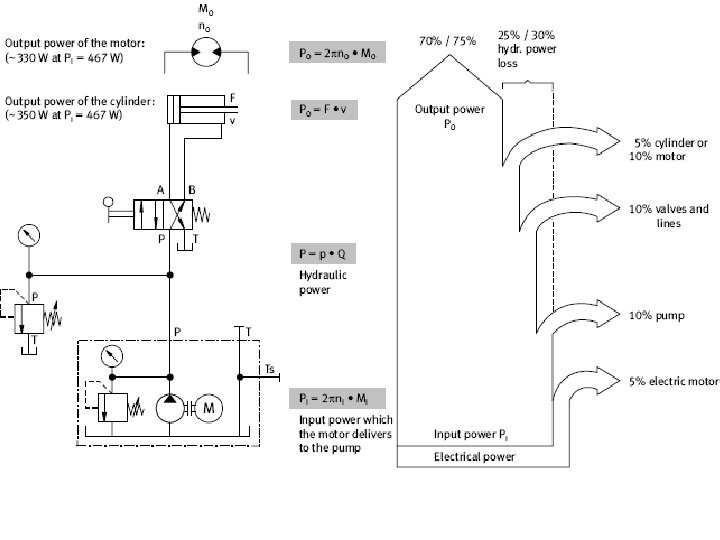
Which is the important part in Hydraulic/Pneumatic System? I. Output power part(Actuators) II. Control part(Valves) III. Input part(Pumps) IV. Accessories part(Hoses, filters, accumulators…etc)

How can you plan for designing the Hydraulic/Pneumatic Circuit The max required pressure The required pump cost

To rise a weight of 30000 N for a distance 70 cm • Does it require a hydraulic or pneumatic circuit? • Which control is required? • What is the type of cylinder and what is its bore and stroke? Stroke =at least 70 cm Bore= d mm F=P. A N , assume P=100 bar

• A = 0. 003 m 2 • A = πd 2/4 = 0. 003 m 2 • d= • The required pump depends on the velocity V Q = A. V, if V= 2 cm/s Q = 0. 003 x 0. 02 = 6. 10 -5 m 3/s = 3. 6 L/min • The required power for driving the pump P=p. Q P = 100. 105 x 6. 10 -5 = 600 watt

• Reservoir volume =3 -5 Q = 3 x 3. 6 L V tank=10. 8 L • Hoses diameter and max pressure
 Dimensions design • Type(single/double acting) • Cylinder diameter • Rod")
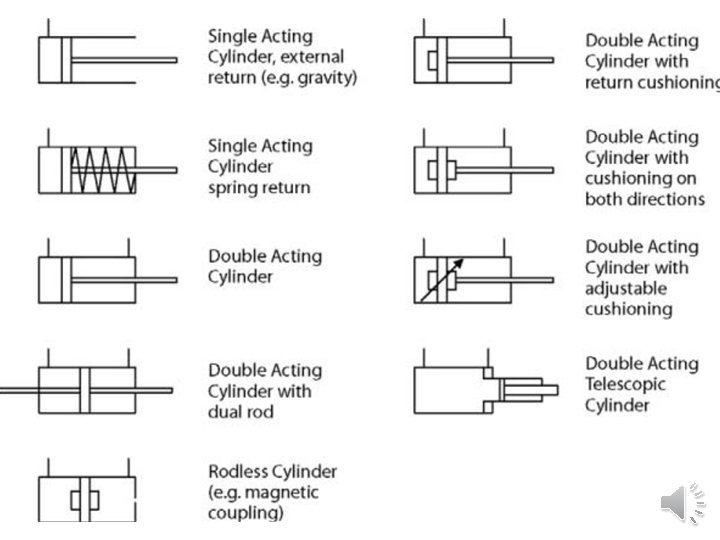
Linear actuator (hydraulic/pneumatic cylinder) Dimensions design • Type(single/double acting) • Cylinder diameter • Rod diameter • Stroke Given • Load depends on P max. &A • Velocity • stroke F = P. A 2 • F= P. (A 2 – A 3) • F= P. A 1 • F= P. A. η , • F/Pη. A • A = πd 2/4 • D=√ 4 F/ πP η • η efficiency hyd=0. 9 • η pneumatic= 0. 50

Choosing cylinder diameter according to load and operating pressure

Piston speed for pneumatic cylinders • V =Q/A

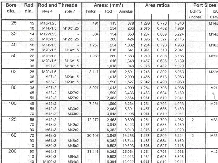
Example 1: it is required to choose a pneumatic cylinder to rise a load of 7000 N for using an operating pressure of 5 bar (take η pneumatic= 0. 50) • D=√ 4 F/ πP η D=√ 4*7000/ π*5*0. 5= 0. 1888 m=189 mm • So we will choose a cylinder diameter > 189 mm ≈200 mm • Rod dia. =40 mm Cylinder bore 8 10 12 16 20 25 32 40 Rod dia 4 4 6 6 12 12 12 18 Cylinder bore 50 63 80 100 125 160 200 250 Rod dia. 18 22 22 30 30 40 40 50

Standard values of rod dia. According to pneumatic and hydraulic cylinder bore Cylinder bore 8 10 12 16 20 25 32 40 Rod dia 4 4 6 6 12 12 12 18 Cylinder bore 50 63 80 100 125 160 200 250 Rod dia. 18 22 22 30 30 40 40 50
 • Displacement")
Rotary actuator design Rotary actuator features • Type( gear, vane, axial, radial) • Displacement • (Speed n rpm) Q = n. V (V volume L) • Power P = T. ω = T. 2π n • Torque T = P. V/2. π
- Slides: 27