HW SW CODESIGN AND PROGRAM MODELLING Fundamental issues


 • DFG -Executing is controlled by data and doesn’t")


- Slides: 25
H/W , S/W CO-DESIGN AND PROGRAM MODELLING • Fundamental issues in h/w s/w codesign: Selecting the model: models are used for capturing and describing the system characteristics • Consisting of objects and composition rules. • Most often the designers switch between a variety of models from the requirements specification to the implementation aspect of the system design(bcoz objective varies with each phase)
• Selecting the architecture: specifies how a system is going to implement in terms of the number and types of different components and the interconnection among them( CISC, RISC, SIMD, MIMD etc) • Controller arch implements the finite state machine model • Data path arch is best for data flow graph model where o/p is generated as a result of a set of predefined computations on the input data • It may contain registers, couters, memories and ports
• Finite state machine data path combines controller arch with data path. It implements a controller (control inputs) with data path(processes the data) • Complex instruction set computing CISC : can perform large complex operation • Use of single complex instruction reduces the program memory access and program memory size requirement
• RISC is designed to operate on registers • RISC arch supports extensive pipelining • VLIW very long instruction word implements multiple functional units (ALU, multipliers etc) in data path. • Parallel processing arch implements multiple concurrent processing elements PE and each may associate a data path containing register and local memory (eg. SIMD, MIMD)
• Selecting the language : language captures a computational model and maps it into architecture • No hard and fast rule to specify the language • Language should capture the model easily • Partitioning system requirements into h/w and s/w : it may be possible to implements the system requirement s in either h/w or s/w
COMPUTATIONAL MODELS IN EMBEDDED DESIGN • Data flow graph/ diagram DFG model: translates the data processing requirements into a data flow graph • Emphasis on the data and operations on data • Data represented using a circle and data flow is represented using arrows • Inward arrow to the process( circle) is i/p data and outward arrow from the process (circle) is o/p data
Control data flow graph/diagram (CDFG) • DFG -Executing is controlled by data and doesn’t involve any control operations (conditionals) • Used for modelling application involving conditional program execution • Contains both data operations and control operations • Contains both data flow nodes and decision nodes where as DFG contains only data flow nodes
State machine model • Used for reactive or event-driven e. s whose behavior are dependent on state transitions. • Model describes the system with ‘states’, ‘events’, ‘actions’, and ‘transitions’ • State- representation of current situation • Event- i/p to the state • Transitions- movement from one state to another • Action- activity to be performed by the state m/c • An FSM is one in which the no of states are finite • Eg: automatic seat belt warning system • 1. when the vehicle ignition is on and the seat belt is not fastened within 10 sec , the system generates an alarm for 5 sec • 2. the alarm is turned off when the alarm time expires or if the driver fastens the belt if the ignition switch is turned off , whichever happens first
FSM model for automatic seat belt warning system
FSM model for timer
FSM model for automatic tea/coffee vending machine
FSM model for coin operated telephone system
Sequential program model • Functions or processing requirements are executed in sequence • Program instructions are iterated executed conditionally and the data gets transformed through a series of operations • FSM s are good choice • Another tool used for modeling is flow charts • Flow chart models the execution flow • Eg. Seat belt warning system
Flowchart approach for modeling the ‘seatbelt warning’ system explained in the FSM modelling section #define ON 1 #define OFF 0 #define YES 1 #define NO 0 Void seat_belt_warn() { Wait_10 sec(); If (check_ignition_key()==ON) { If (check_seat_belt()==OFF) { Set_timer(5); Start_alarm(); While ((check_seat_belt()==OFF) & (check_ignition_key()==OFF) &&(timer_expire()== NO)); Stop alarm(): } } }
Concurrent/communicating process model • Models concurrently executing tasks/processes • Sequential execution leads to a single sequential execution of task and thereby leads to poor processor utilization, when task involves i/o waiting, sleeping • Can split the task into multiple subtasks and switch between them • This requires additional overheads in task scheduling, task synchronization and communication • Eg; seat belt warning system • 1. timer task for waiting for 10 sec • 2. for checking the ignition key status • 3. for checking the seat belt status • 4. for starting and stopping the alarm • 5. alarm timer task for waiting 5 sec • Can not execute these 5 randomly or sequentially. Need to synchronize their execution
Object oriented model • It disseminates a complex s/w into simple pieces called objects. • Re-usability, maintainability and productivity • Object is characterized by a set of unique behavior and state • Class is an abstract description of a set of objects • State by variable and behavior by functions • Characteristics of object oriented model
Unified modeling language UML • Is visual modeling language for object oriented design • Set of unique diagrams are used for capturing, designing and deployment • UML building blocks: ‘things’ ‘relationships’ and ‘diagrams’ are fundamental building blocks • 1. Things: • Structural: represents the static parts of UML model. class, interface , use case component etc
• Class: a template describing a set of objects identifier variable methods • Interface: collection of externally visible operations which specify a service of a class • Use case: a set of sequence of actions name
• Component: physical packaging of classes and interfaces Name • Node: a computational resource exising at run time • Behavioral: represents mostly dynamic parts of a UML model. Interaction, activity etc • Interaction: set of objects exchanging messages for a specific purpose
• State machine : behavior specifying the sequence of states in response to events name • Grouping: a package and subsystems • Package: organises elements in to packages. It is only a conceptual thing • Annotational : explanatory parts • Note: explanatory element contains formal informal explanatory text
• 2. Relationships: they express the type of the relationship between UML elements. • Association: link between objects • Aggregation: represents a part of relationship • Composition: • Aggregation with strong ownership relation t represent the component of a complex object • Generalisation: represents a parent child relationship child • parent
• Dependency: represents the relationship in which one element uses or depends on another element • ----- • Realization: relationship between two elements in which one element realizes the behavior specified by the other element • • element 1 element 2
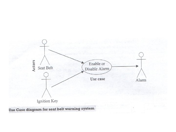
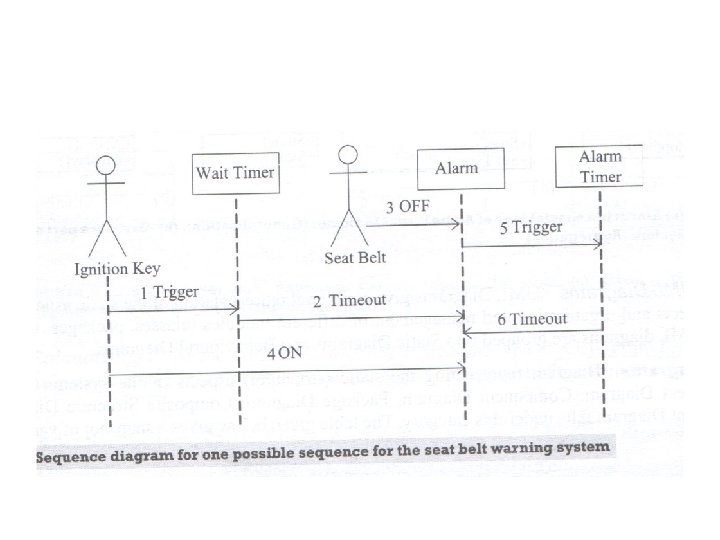
• 3. UML diagrams: gives a picotrial representation of the satic aspects behavioral aspects , organisation and management of different modules (class, package) of the system • Static diagram: representing static aspects of the system Eg: Class diagram, object diagram, package diagram • Behavioral diagram: representing dynamic aspects of the system Eg: use case diagram , sequence diagram, state diagram Use case diagram used for capturing system functionality as seen by users Sequence diagram is a type of interaction diagram representation object interaction with respect to time