HVAC 204 Commercial WalkIn Freezer Simulator and Defrost


")


- Slides: 27
HVAC 204 Commercial Walk-In Freezer Simulator and Defrost Timers
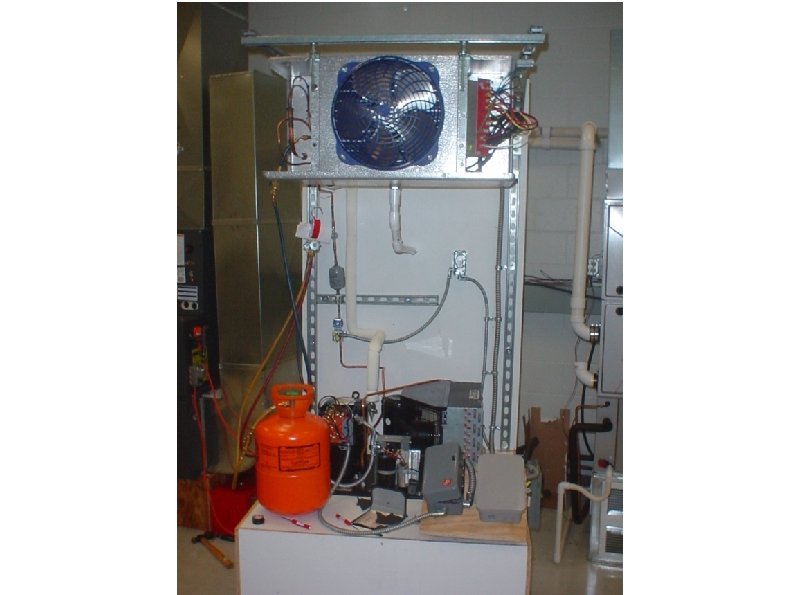
Walk-In Freezer Simulator The walk-in freezer simulator contains everything that a “real” walk-in freezer does. Refrigeration deck (compressor, condenser coil, liquid line receiver, pressure switch, condenser fan). Evaporator Coil Assembly (evaporator coil, evaporator fan, thermally operated switches). Controls Two types of defrost timer. (Only one used at any given time. ) Thermal limit, fan delay and defrost termination switches. Wiring boxes give easy access to the electrical connections for all controls. Electrical Disconnect, Power Cord and Liquid Line Solenoid Switch Refrigerant tubing and flow management devices (filter-dryer, sight glass, TXVtype metering device, liquid line shut-off solenoid).
Evaporator Components Evaporator coil and fan. Defrost Heaters Heating elements attached near the evaporator coils to melt ice. High Limit switch turns off the heating elements to prevent overheating or fires. A Fan Delay switch causes the evaporator fan not to start up until the evaporator coil becomes cold. The Defrost Termination switch returns the system to its refrigeration mode if all the frost is removed from the coils before the timer runs out. It is present but unused in the simulator.
Evaporator Wiring
Defrost Timer Frost builds up on evaporator coil over time, and as the walk in freezer door is opened. Hot and sometimes moist air rushes in whenever the door is opened. A defrost timer acts as the system's “brain”. The defrost timer connects and disconnects both the refrigeration and defrost heating equipment as time passes.
Defrost Timer Construction Defrost timers come in various types. All mechanical Electronic with analog timekeeping. Electronic with digital timekeeping. Most types run constantly. Defrost times and length of time spent in defrost mode can be set by the installer or end user. Defrost cycles usually last 20 minutes, but may take less time. Timers contain a “fail safe” mechanism to stop defrost operation and return to refrigeration mode.
Mechanical Defrost Timer Uses a clock movement and timing motor. Gears and other mechanical parts operate the timer's switches, opening and closing them as specified. A solenoid coil can be used to terminate a defrost cycle earlier than normal, if all the frost has been removed. It is activated by a temperature sensitive switch within the evaporator assembly. Various numbers of switched contacts are available. Must be reset to correct time after a power outage, or when the time changes.
Mechanical Defrost Timer (front and rear view)
Electronic Defrost Timer With Analog Clock Uses a clock movement and timing motor. Electrically operated relays are used as switches. Logic within the timer's circuitry can be used to terminate a defrost cycle earlier than usual , if all the frost has been removed. It is activated by a temperature sensitive switch within the evaporator assembly. Various numbers of switched contacts are available. May be used to replace a failed mechanical timer as a retrofit. Must be reset to correct time after a power outage, or when the time changes.
Electronic Defrost Timer With Analog Clock
Electronic Defrost Timer With Digital Clock Uses a fully electronic digital clock. Usually contains a backup battery to keep the clock running during a power failure. Otherwise identical to the electronic timer with an analog clock.
Electronic Defrost Timer With Digital Clock
Test A Defrost Timer Refer to manufacturer supplied information to find out what voltage is required, where line voltage comes in to the timer, how many contacts a timer has, and which of the contacts are normally open or closed. May be tested with or without power. Verify that the timer motor or clock is running.
Test A Defrost Timer can be tested without power. MAKE SURE ALL POWER IS TURNED OFF! Set meter to resistance testing mode. Disconnect wires from defrost timer terminals, making a note of where they were attached. Test between power input and switch contacts. A closed switch should read very low resistance in ohms. An open switch should indicate infinite resistance. Switches reading moderate to high resistance may have burnt or damaged contacts. If possible, cycle timer through its various modes and test all contacts. Switches can “stick” open or closed. Timer motor should have a measurable resistance (a few hundred to a few thousand ohms). A defrost termination solenoid should also have a measurable resistance.
Test A Defrost Timer Testing without electrical power. Testing normally closed terminal “ 4”. If contact is closed and working properly, very low or no resistance will be shown.
Test A Defrost Timer can be tested with power applied. Use caution around live wires and terminals. Check to make sure that all power feeds are present (no blown fuses or tripped breakers, etc. ) before making this test. Loads attached to switches must be in-circuit and operating correctly, or results will be misleading. A problem could be further in the circuit than it seems. Measurements from hot-to-ground may produce misleading results. Set meter to measure AC voltage. Attach one test lead to the incoming “leg” of power that is switched (usually L 1). Attach the other test lead to the switched terminal. Closed switch contacts that are functioning correctly and attached to working loads will show zero volts AC. Open switch contacts that are functioning correctly and attached to working loads will show “normal” AC voltage (usually 120 or 240 volts AC).
Test A Defrost Timer Testing WITH electrical power applied. Testing normally closed terminal “ 4”. A working, energized load is attached to terminal four. If contact is closed and working properly, no voltage will be shown.
Test A Defrost Timer When testing an electronic timer without power, you may not be able to change contacts from open to closed, or closed to open.
Setting Defrost Timers All defrost timers can be programmed to run defrost cycles when it is convenient or necessary to do so. Programming options include What time to defrost. How long a defrost cycle will last. How often to defrost. Defrost timers are often set to run defrost cycles durung “off peak” times when the walk-in freezer is closed and unlikely to be entered.
Defrost Timer Fail Safe This defrost timer has been set to perform four defrost cycles throughout the day. Each silver screw represents one defrost cycle. A “fail safe” switch will place the system back into the refrigeration mode if the defrost termination thermostat fails to do so. The inner ring of the timer dial represents the fail safe. This timer will place the system back into refrigeration mode after about 45 minutes.
Wiring Diagram For Walk-In Freezer Simulator Shown In The Refrigeration Mode Terminal “N” in timer goes to refrigeration deck (not shown). CLOCK MOTOR Defrost High Limit (break on temp rise) EVAP. ↔ SLIDE FAN DELAY (make on fall) 1 4 N NO NC 2 3 FAN DEFROST HEATERS NC X LINE VOLTAGE TO CLOCK Liquid Line Solenoid Coil uses 120 VAC, opens to allow flow when energized SOLENOID VALVE
Wiring Diagram For Walk-In Freezer Simulator Shown In Defrost Mode DEFROST SOLENOID CLOCK MOTOR Unused Defrost Termination High Limit Stat EVAP. DEFROST TERMINATION FAN DELAY 1 4 1 closed 2 -4 4 & closed N open 2 3 FAN X LINE VOLTAGE TO CLOCK DEFROST HEATERS
Switching from Defrost Back Into Freeze • In most walk-in freezers, a defrost termination switch within the evaporator assembly closes when the temperature is high enough (about 55°F). • When the defrost termination switch closes, it energizes a solenoid or relay within the defrost timer that will return the timer to the refrigeration mode. • The fan is delayed until the temperature of the evaporator is down to approximately 25°F. • The fan delay and defrost termination switch are often located in the same physical unit (a single pole, double throw switch). • A defrost termination switch is present but unused in the simulator.
Electronic Defrost Timer
Electronic Defrost Timer • Functions identically to the mechanical timer. • Uses electronic logic and relays instead of moving parts to switch refrigeration and defrost components on and off as needed. • Terminal layout is different from the mechanical timer. • Operating parameters are adjustable to suit many replacement timer needs. • Timer movement is still mechanical in nature, but fully electronic digital timers exist. • Automatically detects incoming voltage (110/220 volts AC, single phase).
Electronic Defrost Timer Alternate wiring: switch evaporator fan through terminal F, refrigeration deck through terminal 4. Defrost termination “X” is unused. Defrost Marker Defrost High Limit (break on temp rise) EVAP. Refrigeration Deck (Compressor) FAN DELAY (make on fall) DEFROST HEATERS F 3 1 2 4 N X L 1 L 2 LINE VOLTAGE TO CLOCK Liquid Line Solenoid Coil uses 120 VAC, opens to allow flow when energized SOLENOID VALVE