
HV Power Supply Filtering and EMI to Readout

- Slides: 17
HV Power Supply Filtering and EMI to Readout Sergio Rescia and Bo Yu Brookhaven National Laboratory Sept. 18, 2018
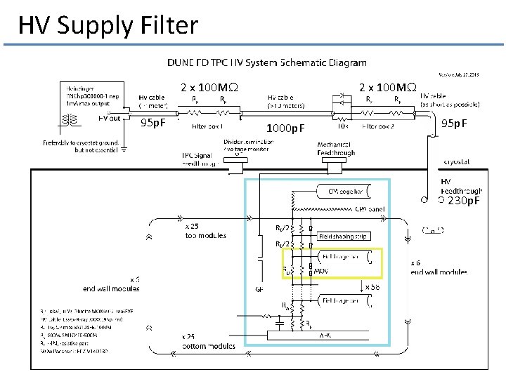
HV Supply Filter 2 x 100 MW 95 p. F 2 x 100 MW 1000 p. F 95 p. F 230 p. F
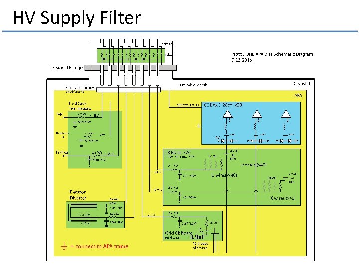
HV Supply Filter 3. 9 n. F
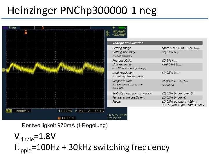
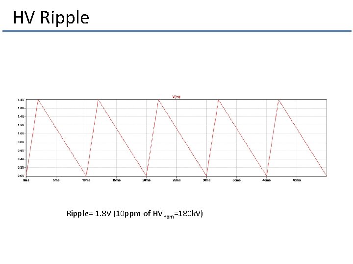
Heinzinger PNChp 300000 -1 neg Vripple=1. 8 V fripple=100 Hz + 30 k. Hz switching frequency
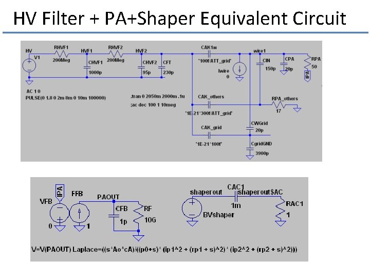
HV Filter + PA+Shaper Equivalent Circuit
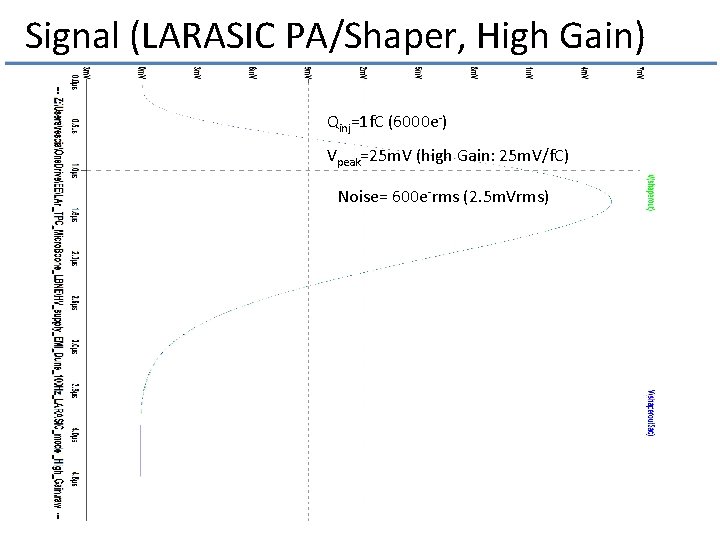
Signal (LARASIC PA/Shaper, High Gain) Qinj=1 f. C (6000 e-) Vpeak=25 m. V (high Gain: 25 m. V/f. C) Noise= 600 e-rms (2. 5 m. Vrms)
HV Ripple= 1. 8 V (10 ppm of HVnom=180 k. V)
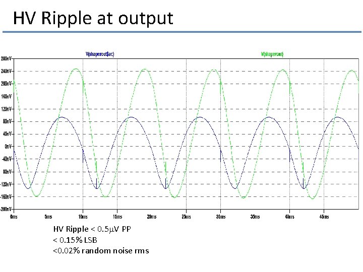
HV Ripple at output HV Ripple < 0. 5 m. V PP < 0. 15% LSB <0. 02% random noise rms
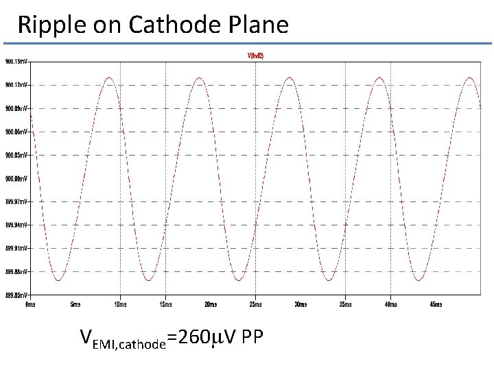
Ripple on Cathode Plane VEMI, cathode=260 m. V PP
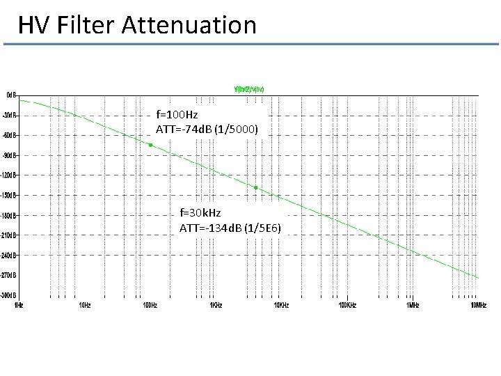
HV Filter Attenuation f=100 Hz ATT=-74 d. B (1/5000) f=30 k. Hz ATT=-134 d. B (1/5 E 6)
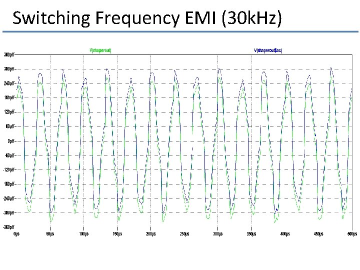
Switching Frequency EMI (30 k. Hz)
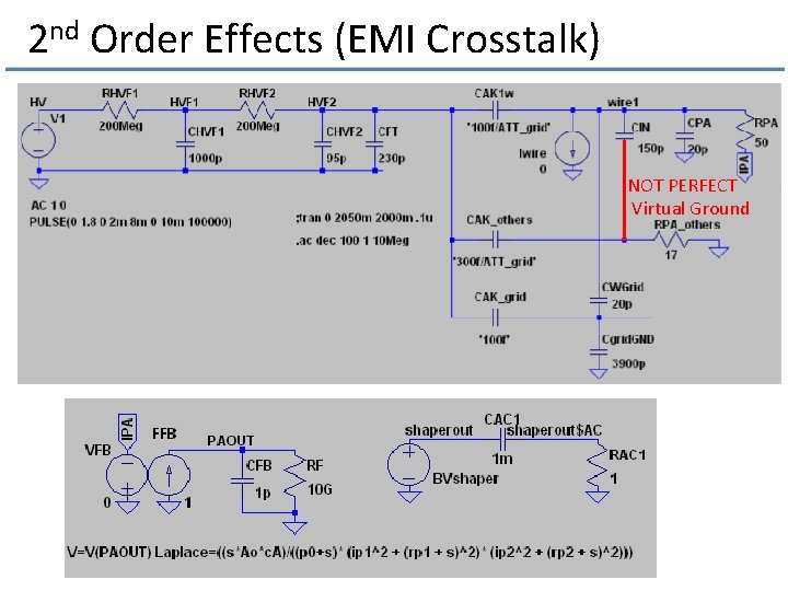
2 nd Order Effects (EMI Crosstalk) NOT PERFECT Virtual Ground
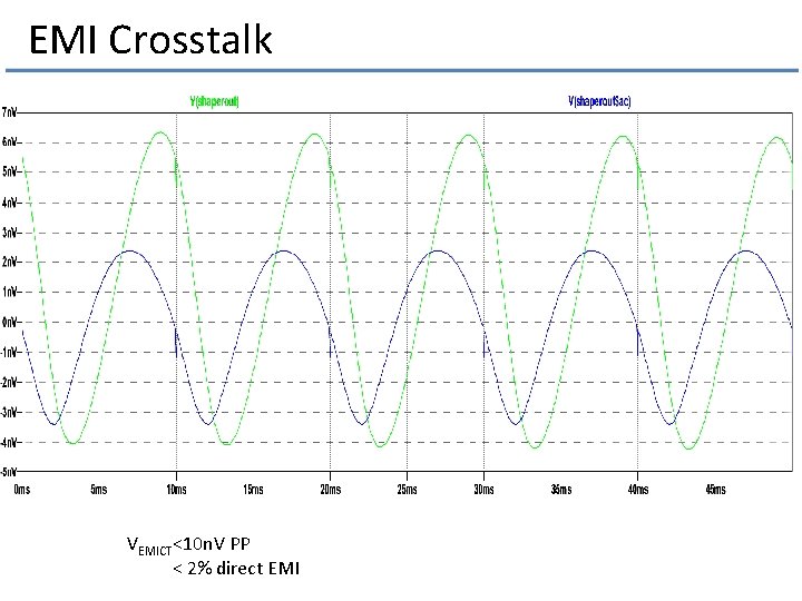
EMI Crosstalk VEMICT<10 n. V PP < 2% direct EMI
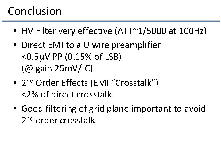
Conclusion • HV Filter very effective (ATT~1/5000 at 100 Hz) • Direct EMI to a U wire preamplifier <0. 5 m. V PP (0. 15% of LSB) (@ gain 25 m. V/f. C) • 2 nd Order Effects (EMI “Crosstalk”) <2% of direct crosstalk • Good filtering of grid plane important to avoid 2 nd order crosstalk
Additional Slides
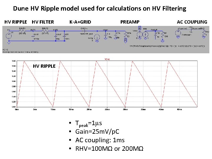
Dune HV Ripple model used for calculations on HV Filtering HV RIPPLE HV FILTER K-A+GRID PREAMP HV RIPPLE • • Tpeak=1μs Gain=25 m. V/p. C AC coupling: 1 ms RHV=100 MΩ or 200 MΩ AC COUPLING
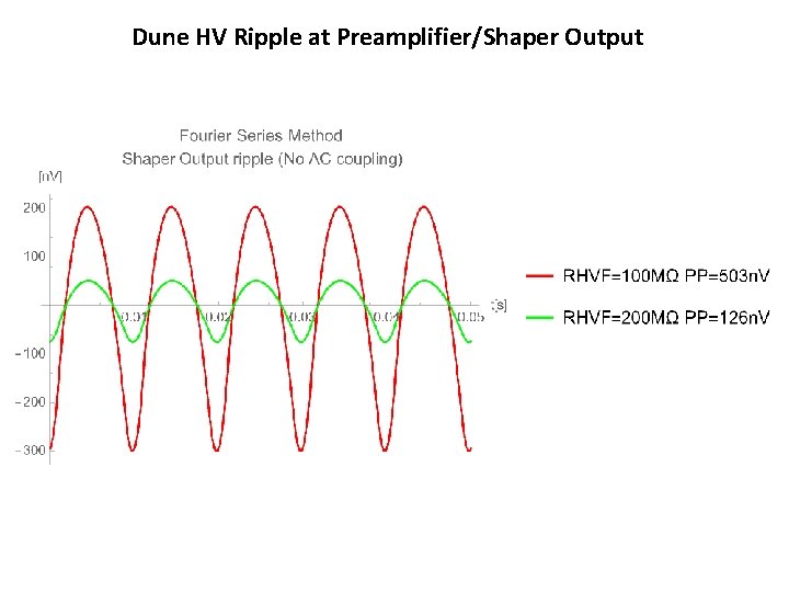
Dune HV Ripple at Preamplifier/Shaper Output