HUMIDITY Humidity is the amount of water vapor


 is the ratio of water vapor")


 • Where: C = Capacitance in Pico farads (p. F) •")


 • This is simplest type of tool dynamometer as shown")


- Slides: 96
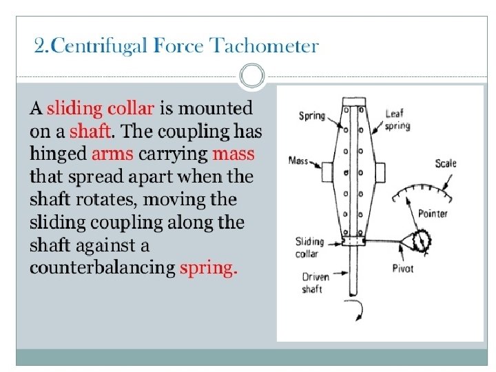
HUMIDITY Humidity is the amount of water vapor in the air.
Humidity • There are three main measurements of humidity: absolute, relative and specific. • Absolute humidity is the total amount of water vapour present in a given volume of air. • Absolute humidity is the mass of the water vapor ( ), divided by the volume of the air and water vapor mixture ( ), which can be expressed as: • The absolute humidity changes as air temperature or pressure changes.
Relative humidity • Relative humidity as a percentage that the moisture present bears to the maximum amount of moisture that could be present at the location temperature without condensation taking place.
Relative Humidity • The relative humidity of an air-water mixture is defined as the ratio of the partial pressure of water vapor (H 2 O) in the mixture to the saturated vapor pressure of water at a given temperature. • Thus the relative humidity of air is a function of both water content and temperature. • Relative humidity is normally expressed as a percentage and is calculated by using the following equation:
Specific humidity • Specific humidity (or moisture content) is the ratio of water vapor mass ( ) to the air parcel's total (i. e. , including dry) mass ( ) and is sometimes referred to as the humidity ratio. • Specific humidity is approximately equal to the "mixing ratio", which is defined as the ratio of the mass of water vapor in an air parcel to the mass of dry air for the same parcel. • Specific Humidity is defined as:
• specific humidity is also defined as the ratio of mass water vapor to the total mass of the system (dry air plus water vapor).
Why is humidity important? • It affects many properties of air, and of materials in contact with air. • Water vapour is a key agent in both weather and climate, and it is an important atmospheric greenhouse gas. (Without water vapour we would be 31 °C colder on Earth).
Why is humidity important? • A huge variety of manufacturing, storage and testing processes are humidity-critical. • Humidity measurements are used to prevent condensation, corrosion, mould, warping or other spoilage - highly relevant for foods, pharmaceuticals, chemicals, fuels, wood, paper, and many other products. • Air-conditioning systems in buildings often control humidity, and significant energy may go into cooling the air to remove water vapour. • Humidity measurements contribute both to achieving correct environmental conditions and to minimizing the energy cost of this.
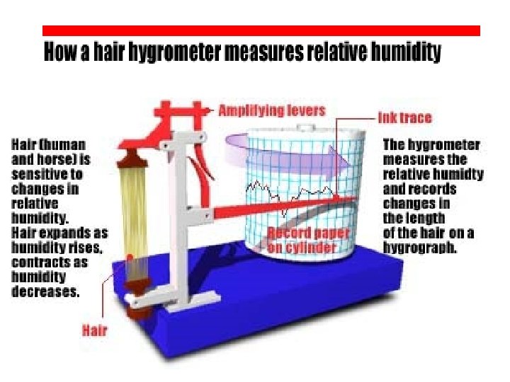
• The length of a strand of human hair changes with different relative humidities. • As the relative humidity increases, hair becomes longer, and as the humidity drops it becomes shorter. On very humid days, your hair actually becomes longer and this extra length causes the frizziness that gives us bad hair days. • An instrument that uses hair to measure humidity is known as a hair hygrometer. • This instrument uses strands of human or horse hair with the oils removed attached to levers that magnify a small change in hair length. • An ink pen and rotating cylinder, known as a hygrograph, can provide a record of how relative humidity varies throughout the day.
• The disadvantages of the hair hygrometer and hygrograph are that they are not as accurate as other kinds of hygrometers such as the sling psychrometer. • Also, a hair hygrometer needs frequent adjustment and calibration. • A hair hygrometer also tends to have large errors at very high and very low relative humilities.
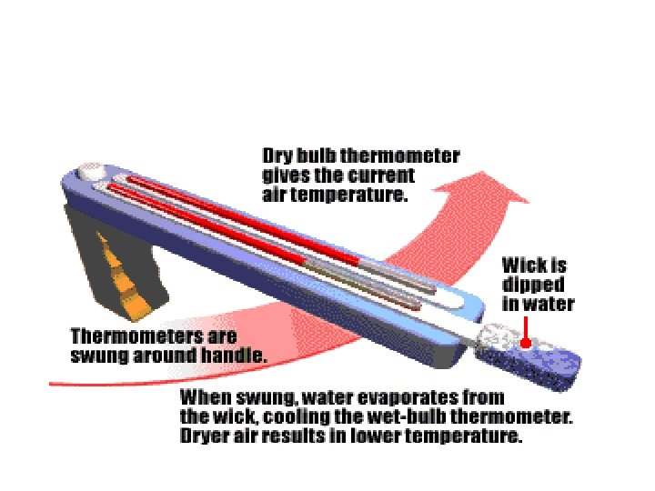
Sling psychrometer • It consists of two glass thermometers containing a liquid, usually mercury. • One is left dry to record the true temperature, while the other is covered in water. • The wet thermometer is then swung around, causing some of the water to evaporate. • The lower the relative humidity, the more water will evaporate and the more the wet thermometer will cool down. • By comparing the temperatures of the wet and dry thermometers to a chart called a psychometric chart, a scientist can determine how humid the air is.
Liquid level Measurement • Float Devices
Float Devices • Float devices use the buoyancy of a float to indicate the liquid level in the tank. • One common approach is to attach the float to a chain. • The chain is attached to a counterweight which indicates the level as the float moves up and down. • These types of device are often found on large atmospheric storage tanks.
• Benefits • Float Type level sensors do not require external energy sources to operate. • Since they are simple robust machines it is easy to repair. • The cost of these units makes them on the economical side, Prices would increase with higher quality materials and valve size. • Floats could be made out of plastics or metals (steel, stainless steel, etc. ). Material selection will depend on the application; more chemically resistant materials would be used for corrosive mediums.
• Restrictions • Float type level sensors should only be used in clean fluids. • Fluids that are a suspension of solids or slurries could foul the operation of the machine. • Anything that could increase friction on the mechanical linkages could increase the dead band, which is the delay the sensor experiences due to the excess of force required to overcome the static friction of a non-moving system. • An excess of force is required to be built up, so a float type level sensor will not respond immediately to changes in level
Bubblers • Bubblers measure the depth of a liquid by forcing air down a tube mounted in a tank or wet well. • The air discharges or bubbles out of the tube at its opening near the bottom of the vessel. • The pressure required to force air down the tube is proportional to the liquid level.
Bubblers • A typical Bubbler system consists of an air compressor or pressure source, a pressure sensor and control and calibration electronics, and a bubble tube made of rubber, plastic or stainless steel. • A source of clean, dry gas is required. Accuracy is generally 0. 5 to 1% of full scale. • Bubblers are often used in wastewater treatment for basin and wet well level applications.
Sight-type Instruments • There are three common sight-type level sensors: glass gauges, displacers, and tape floats. • Glass gauges are the most widely used instruments for measuring the level in a process tank. • Two types of level glass gauges are used to measure liquid level: tubular and flat. • The tubular type works in the same way as a manometer, that is, as the liquid level in a vessel rises or falls the liquid in the glass tube will also rise or fall. • The gauges are made of glass, plastic, or a combination of the two materials. .
• Figure 6 -1 shows two common applications of tubular sight glasses: an open or vented process vessel and a pressurized vessel. • For the pressurized tank, the upper end of the tube is connected to the tank.
• . This creates an equilibrium pressure in both ends of the tube, and the liquid in the tube rises to the same level as the liquid in the vessel. • A calibrated scale is normally mounted next to the sight gauge to indicate the level in the tank.
Capacitance • The principle of capacitive level measurement is based on the change of capacitance. • There are two plates in capacitive sensor: one plate acts as an insulated electrode and the other plate acts as a tank wall. • The capacitance depends on the liquid level. • An empty tank has low capacitance while a filled tank has higher capacitance.
Capacitance • A simple capacitor consists of two electrode plates separated by a small thickness of an insulator such as solid, fluid, gas, or vacuum. • The Value of C depends on dielectric constant used, area of the plate and also on the distance between the plates.
• C=E(KA/d) • Where: C = Capacitance in Pico farads (p. F) • E = a constant known as the absolute permittivity of free space • K = Relative dielectric constant of the insulating material • A = Effective area of the conductors • d = Distance between the conductors • This change in capacitance can be measured by using an AC Bridge.
• Construction and Working • The measurement of liquid level is done by applying a Radio Frequency signal between the conductive probe and the vessel wall. • The Radio Frequency signal results in a very-low current which flows through the dielectric process material in the tank from the probe to the vessel wall. • If the liquid level in the tank drops, then the dielectric constant decreases, which leads to the drop in capacitance reading as well as minute drop in current flow. • This change can be detected by the liquid-level switch’s internal circuitry and translated into relay state changes of the level switch in case of a point level detection.
Advantages and disadvantages • The main advantages of these capacitance systems include easy installation, broad application range, good accuracy suitable for variety of applications and highly recognized and well -proven technology. • The disadvantages include sensitivity to changes in the measurable properties such as dielectric constant and conductivity which creates an issue; furthermore, it is an intrusive system.
Radiation method • The radiation method is an expensive technique, which uses a radiation source and detector system located outside a liquid-filled tank in the manner shown in Figure. • The absorption of both beta rays and gamma rays varies with the amount of liquid between the source and detector, and hence is a function of liquid level.
• Caesium-137 is a commonly used gamma-ray source. • The radiation level measured by the detector I is related to the length of liquid in the path x according to: • where I 0 is the intensity of radiation that would be received by the detector in the absence of any liquid, is the mass absorption coefficient for the liquid and is the mass density of the liquid.
• In some applications, the radiation source can be located in the centre of the bottom of the tank, with the detector vertically above it. • Apart from use with liquids at normal temperatures, this method is commonly used for measuring the level of hot, liquid metals. • However, because of the obvious dangers associated with using radiation sources, very strict safety regulations have to be satisfied when applying this technique. • Because of the many difficulties in using this technique, it is only used in special applications.
Ultrasonic level sensor • The transducer of an ultrasonic level sensor emits high frequency (20 - 200 k. Hz) acoustic waves. • The emitted waves hit the liquid, sludge, or solid to be measured, and part of the emitting waves are reflected back to the transducer. • From the time lag between the emission and the reflection of the acoustic waves, the level is measured. • Results vary with varying levels of temperature, pressure, and humidity at the surrounding atmosphere. In other words, temperature, pressure, and humidity are the sources of error for these types of sensor.
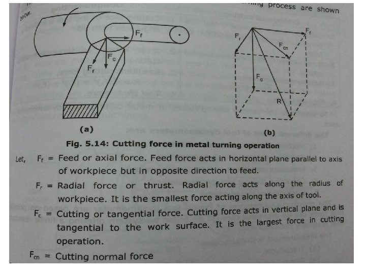
Force measurement Orthogonal cutting Oblique cutting Cutting force of the tool is perpendicular to the direction of feed. Cutting face of the tool is inclined at angle less than 90. It is known as two dimensional cutting It is known as three dimensional cutting Tool life is less Tool life is more Generally parting off on lathe , This method of cutting is used in broaching and slotting operations almost all machining operation are done in this method.
Mechanical method (tool dynamometer) • This is simplest type of tool dynamometer as shown in fig. • It consist of dial indicator for the measurement of forces. • The dial indicator is calibrated to read the cutting forces. • The calibration is done by considering the deflection. • The deflection produced is directly proportional to the cutting forces. • The dial indicator is always placed in the direction of cutting forces. • Fig shows the set up of mechanical tool dynamometer.
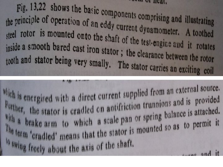
Eddy current dynamometer
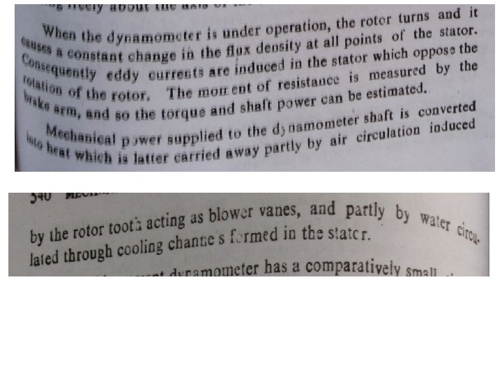
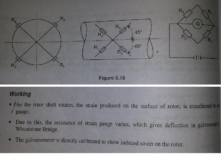
Strain gauge transmission Dynamometer
• optical
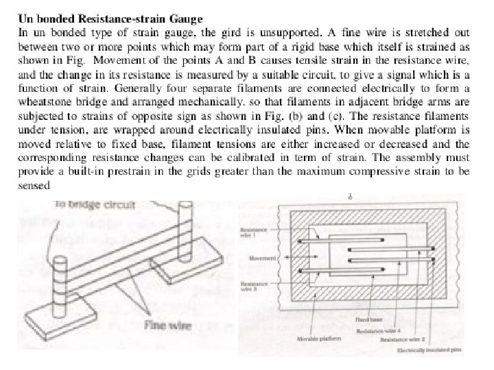
Unbonded resistance strain guage
3 sleeping clutch tachometer
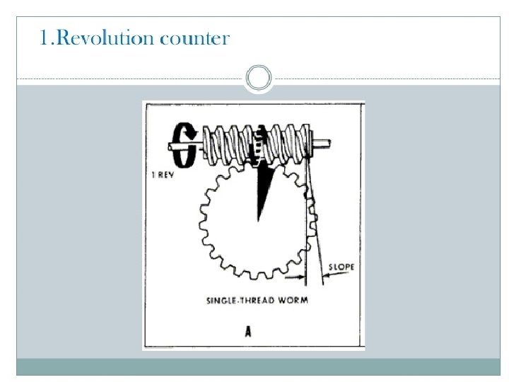
• It consists of worm and worm wheel. • The shaft whose speed is to be measured is connected to worm. • Along with shaft, worm and depending on velocity ratio , worm wheel rotates. • One rotation of worm causes the worm wheel to move by one tooth. • A pointer on worm wheel can be directly calibrated to give number of revolutions made by shaft within prescribed time. • from total revolution in a given time, average speed is calculated. • It is used to measure speed up to 3000 rpm.
Slipping clutch tachometer • It is mechanical type tachometer. • It uses mechanical movements for measurement speed. • A rotating shaft whose speed is to be measured is connected to indicator shaft with the help of slipping clutch.
Slipping clutch tachometer • Friction material is used to avoid metal contact. • During the engagement of clutch , the shaft speed is transferred to indicator shaft and spring attached to it. • The torque on the spring is calibrated in terms of speed which is indicated by pointer moving over a calibrated scale.
Contactless electrical tachometer • • Inductive pick up Capacitive pick up Photoelectric tachometer Stroboscope.
Inductive pick up
• The frequency of induced e. m. f. will depend upon number of teeth of rotor and speed of motor. • The number of teeth of rotor is constant, hence output e. m. f. is directly proportional to speed of rotor. • Let, T be the number of teeth on rotor • P be the number of pulse per sec • N be the speed of rotation in r. p. s. • Then , speed , n= pulse per sec(P)/ number of teeth(T).
Capacitive pick up tachometer
Photoelectric tachometer
Photoelectric tachometer
stroboscope
stroboscope
stroboscope
Load cell When a material is subjected to a load it undergoes fractional deformation which is directly related to the load. The material reverts to its normal dimensions once the load is removed. Fig. (1) shows a cross section of a load cell. Bonded to the circumference of the billet is a combination of wires known as strain gauges.
Load cell. The resistance of these wires changes as the cross-sectional area is varied by tension or compression. It follows therefore that the electrical resistance of the strain gauge will vary in direct proportion to the load applied to the billet
• Four strain gauges are used to detect the deformation of the billet; two "active" and two temperature compensating types. • The characteristics of the strain gauges are accurately matched and together form a simple temperature compensated Wheatstone Bridge. • In the static state, (i. e. no load), the resistance of the four strain gauges is equal, and the bridge is electrically balanced. • With the application of a load, the balance is disturbed an electrical current flows around the Wheatstone Bridge in a direction determined by the applied load. • Load cells of this nature have been made to accommodate up to 2, 500 tons, but the usual ratings are from 2 -50 tons. • With careful manufacture, cells can be constructed to an accuracy of 0. 1 %of the full capacity.
Strain Rosette • Since a single gage can only measure the strain in only a single direction, two gages are needed to determine strain in the εx and εy. • However, there is no gage that is capable of measuring shear strain. • There is a clever solution to finding shear strain. • Three gages are attached to the object in any three different angles.
Strain Rosette • Recall, any rotated normal strain is a function of the coordinate strains, εx, εy and γxy, which are unknown in this case. • Thus, if three different gages are all rotated, that will give three equations, with three unknowns, εx, εy and γ xy. • These equations are,
• Any three gages used together at one location on a stressed object is called a strain rosette.