
How an AC detector works The n electrode
- Slides: 14
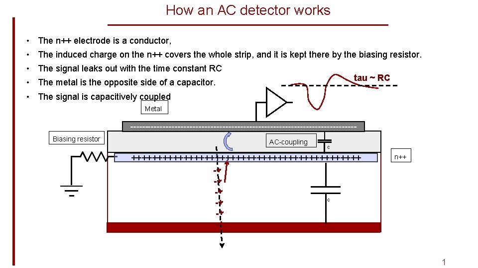
How an AC detector works • The n++ electrode is a conductor, • The induced charge on the n++ covers the whole strip, and it is kept there by the biasing resistor. • The signal leaks out with the time constant RC tau ~ RC • The metal is the opposite side of a capacitor. • The signal is capacitively coupled Metal --------------------------------------Biasing resistor AC-coupling C ++++++++++++++++++++++ -+ -+ -+ C -+ -+ -+ n++ 1
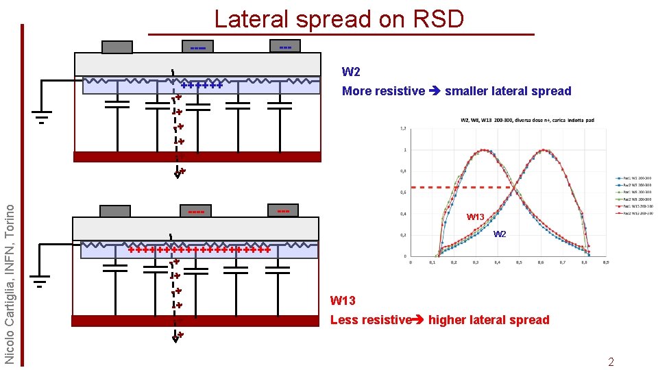
Lateral spread on RSD ---- --W 2 Nicolo Cartiglia, INFN, Torino ++++++ -+ -+ -+ ---- More resistive smaller lateral spread --- W 13 W 2 ++++++++++ -+ -+ -+ W 13 Less resistive higher lateral spread 2
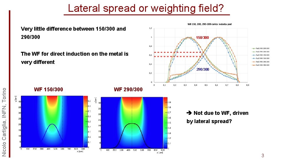
Lateral spread or weighting field? Very little difference between 150/300 and 290/300 150/300 The WF for direct induction on the metal is very different Nicolo Cartiglia, INFN, Torino 290/300 WF 150/300 WF 290/300 Not due to WF, driven by lateral spread? 3
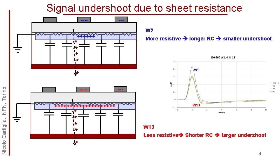
Signal undershoot due to sheet resistance ---- --W 2 Nicolo Cartiglia, INFN, Torino ++++++ -+ -+ -+ ---++++++++++ -+ -+ -+ More resistive longer RC smaller undershoot W 2 --W 13 Less resistive Shorter RC larger undershoot 4
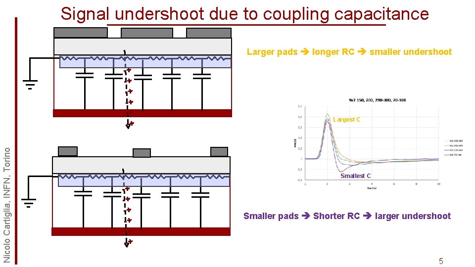
Signal undershoot due to coupling capacitance Larger pads longer RC smaller undershoot Nicolo Cartiglia, INFN, Torino -+ -+ -+ Largest C Smallest C -+ -+ -+ Smaller pads Shorter RC larger undershoot 5
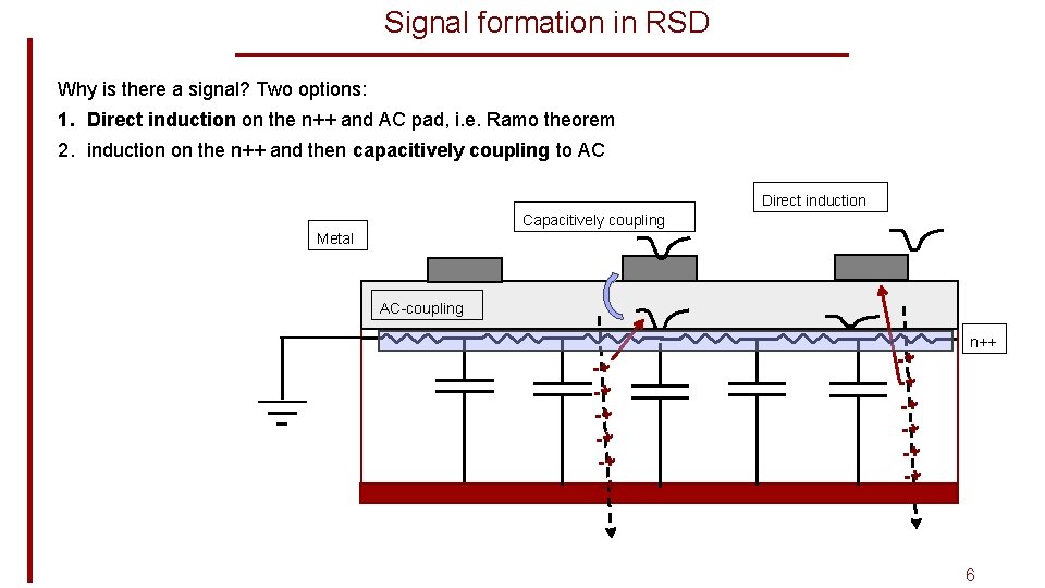
Signal formation in RSD Why is there a signal? Two options: 1. Direct induction on the n++ and AC pad, i. e. Ramo theorem 2. induction on the n++ and then capacitively coupling to AC Direct induction Capacitively coupling Metal AC-coupling -+ -+ -+ n++ 6
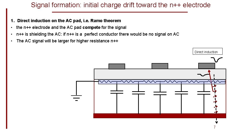
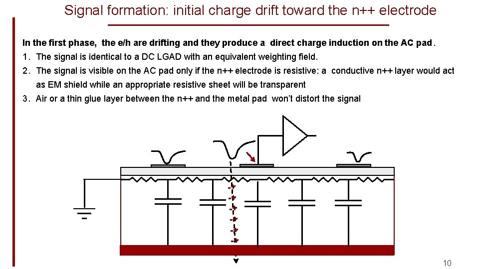
Signal formation: initial charge drift toward the n++ electrode 1. Direct induction on the AC pad, i. e. Ramo theorem • the n++ electrode and the AC pad compete for the signal • n++ is shielding the AC: if n++ is a perfect conductor there would be no signal on AC • The AC signal will be larger for higher resistance n++ Direct induction -+ -+ -+ 7
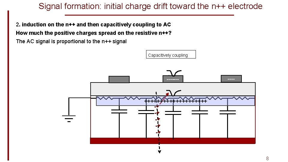
Signal formation: initial charge drift toward the n++ electrode 2. induction on the n++ and then capacitively coupling to AC How much the positive charges spread on the resistive n++? The AC signal is proportional to the n++ signal Capacitively coupling ------- ++++++++++ -+ -+ -+ 8
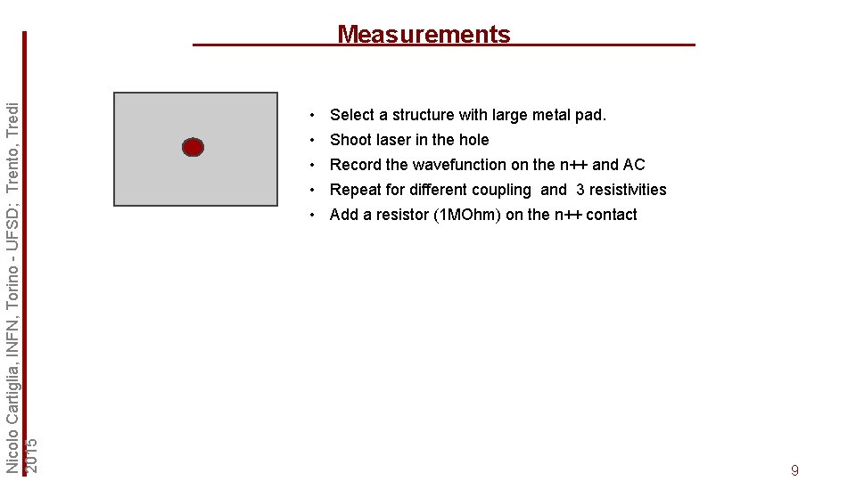
Nicolo Cartiglia, INFN, Torino - UFSD; Trento, Tredi 2015 Measurements • Select a structure with large metal pad. • Shoot laser in the hole • Record the wavefunction on the n++ and AC • Repeat for different coupling and 3 resistivities • Add a resistor (1 MOhm) on the n++ contact 9
Signal formation: initial charge drift toward the n++ electrode In the first phase, the e/h are drifting and they produce a direct charge induction on the AC pad. 1. The signal is identical to a DC LGAD with an equivalent weighting field. 2. The signal is visible on the AC pad only if the n++ electrode is resistive: a conductive n++ layer would act as EM shield while an appropriate resistive sheet will be transparent 3. Air or a thin glue layer between the n++ and the metal pad won’t distort the signal -+ -+ -+ 10
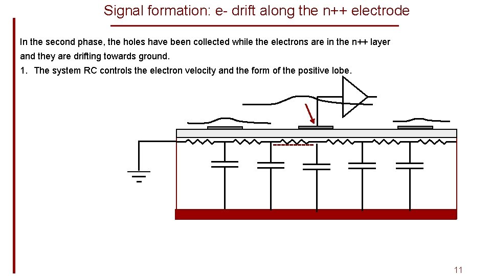
Signal formation: e- drift along the n++ electrode In the second phase, the holes have been collected while the electrons are in the n++ layer and they are drifting towards ground. 1. The system RC controls the electron velocity and the form of the positive lobe. ----- 11
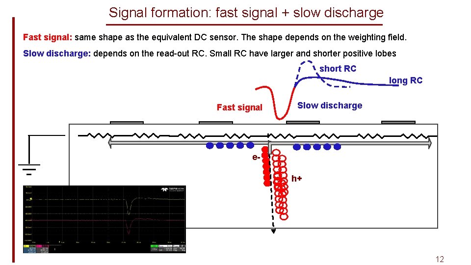
Signal formation: fast signal + slow discharge Fast signal: same shape as the equivalent DC sensor. The shape depends on the weighting field. Slow discharge: depends on the read-out RC. Small RC have larger and shorter positive lobes short RC long RC Fast signal Slow discharge eh+ 12
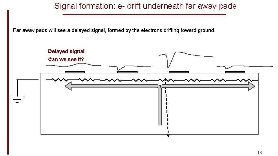
Signal formation: e- drift underneath far away pads Far away pads will see a delayed signal, formed by the electrons drifting toward ground. Delayed signal Can we see it? 13
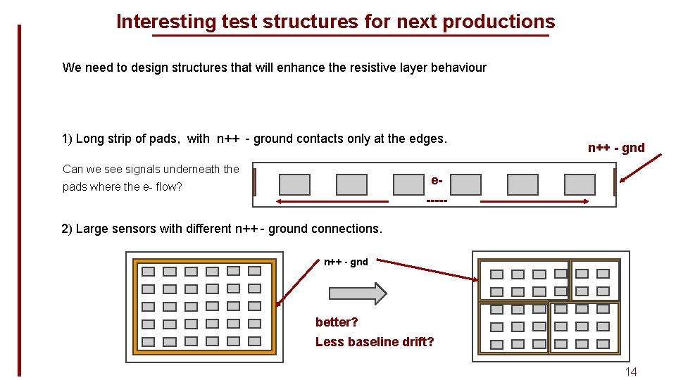
Interesting test structures for next productions We need to design structures that will enhance the resistive layer behaviour 1) Long strip of pads, with n++ - ground contacts only at the edges. Can we see signals underneath the n++ - gnd e- pads where the e- flow? ----- 2) Large sensors with different n++ - ground connections. n++ - gnd better? Less baseline drift? 14