Holography Mon Dec 2 2002 1 History of


- Slides: 18

Holography Mon. Dec. 2, 2002 1

History of Holography Invented in 1948 by Dennis Gabor for use in electron microscopy, before the invention of the laser n Leith and Upatnieks (1962) applied laser light to holography and introduced an important off-axis technique n 2

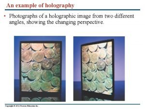
Conventional vs. Holographic photography n Conventional: ¨ 2 -d version of a 3 -d scene ¨ Photograph lacks depth perception or parallax ¨ Film sensitive only to radiant energy ¨ Phase relation (i. e. interference) are lost 3

Conventional vs. Holographic photography n Hologram: ¨ Freezes the intricate wavefront of light that carries all the visual information of the scene ¨ To view a hologram, the wavefront is reconstructed ¨ View what we would have seen if present at the original scene through the window defined by the hologram ¨ Provides depth perception and parallax 4

Conventional vs. Holographic photography n Hologram: ¨ Converts phase information into amplitude information (in-phase - maximum amplitude, out-of-phase – minimum amplitude) ¨ Interfere wavefront of light from a scene with a reference wave ¨ The hologram is a complex interference pattern of microscopically spaced fringes ¨ “holos” – Greek for whole message 5

Hologram of a point source Construction of the hologram of a point source Any object can be represented as a collection of points Photographic plate Reference wave plane x z y Photosensitive plate 1. Records interference pattern (linear response) 2. Emulsion has small grain structure ( ) Object wave - spherical 6

Point object hologram construction: Intensity distribution on plate n Reference wave n Object wave n Intensity distribution on plate 7

Hologram construction Gabor zone plate Maxima for kr=2 m or r=m i. e. if the OPL difference OZ – OP is an integral number of wavelengths, the reference beam arrives at P in step with the scattered (i. e. object) beam. 8

Hologram n When developed the photographic plate will have a transmittance which depends on the intensity distribution in the recorded plate n tb n – backgrond transmittance due to |R|2 term B – parameter which is a function of the recording an developing process 9

Hologram reconstruction n When illuminated by a coherent wave, A(x, y), known as the reconstruction wave, the optical field emerging from the transparency is, n i. e. a superposition of 4 waves n If A(x, y)=R(x, y), i. e. reconstruction and reference waves are identical, 10

Hologram reconstruction n Three terms in the reconstructed wave Direct wave – identical to reference wave except for an overall change in amplitude Conjugate wave – complex conjugate of object wave displaced by a phase angle 2 Object wave – identical to object wave except for a change in intensity 11

Hologram reconstruction n Three terms in the reconstructed wave of the point hologram Direct wave – identical to reference wave (propagates along z) except for an overall change in amplitude Conjugate wave – spherical wave collapsing to a point at a distance z to the right of the hologram -a real image - displaced by a phase angle 2 kz Object wave – Spherical wave except for a change in intensity B|r|2 i. e. reconstructed wavefront 12

Direct, object and conjugate waves Object wave Reference wave Real image Virtual image Conjugate wave -z Direct wave z z=0 13

Hologram : Direct, object and conjugate waves n n Direct wave: corresponds to zeroth order grating diffraction pattern Object wave: gives virtual image of the object (reconstructs object wavefront) – first order diffraction Conjugate wave: conjugate point, real image (not useful since image is inside-out due to negative phase angle) – first order diffraction In general, we wish to view only the object wave – the other waves just confuse the issue 14

Off-axis- Direct, object and conjugate waves Use an off-axis system to record the hologram, ensuring separation of the three waves on reconstruction Reference wave Object wave Direct wave Virtual image Conjugate wave Real image 15

Hologram – Reflection vs. Transmission n n Transmission hologram: reference and object waves traverse the film from the same side Reflection hologram: reference and object waves traverse the emulsion from opposite sides View in Transmission View in reflection 16

Hologram: Wavelength n n With a different color, the virtual image will appear at a different angle – (i. e. as a grating, the hologram disperses light of different wavelengths at different angles) Volume hologram: emulsion thickness >> fringe spacing ¨ Can be used to reporduce images in their original color when illuminated by white light. ¨ Use multiple exposures of scene in three primary colors (R, G, B) 17

Hologram: Some Applications n Microscopy M = r/ s Increase magnification by viewing hologram with longer wavelength ¨ Produce hologram with x-ray laser, when viewed with visible light M ~ 106 ¨ 3 -d images of microscopic objects – DNA, viruses ¨ n Interferometry Small changes in OPL can be measured by viewing the direct image of the object and the holographic image (interference pattern produce finges Δl) ¨ E. g. stress points, wings of fruit fly in motion, compression waves around a speeding bullet, convection currents around a hot filament ¨ 18


