HIGHWAYS UNIT 1 HIGHWAY PLANNING AND ALIGNMENT History


 • Mughul Period")


 Ø engaged in")


 Land Width (90")


 2. Reconnaissance")
 2) 3) 4) 5) 6) 7) Key map Index map")

 Scale -1: 2, 50,")


 Provisional alignment Identification ( Map study) 2) Reconnaissance survey 3)")


- Slides: 64
HIGHWAYS
UNIT 1. HIGHWAY PLANNING AND ALIGNMENT • History of road development in India. • Classification of highways. • Institutions for Highway planning, design and implementation at different levels • Factors influencing highway alignment • Engineering surveys for alignment, objectives, conventional and modern methods.
Roman Road Construction Basic cross section
History of Road Development in India • Ancient Period (3500 BC) • Mughul Period (15 th Century) • British Period (17 th & 18 th Century) • Free India (1950 onwards)
Types of Ancient Indian Roads • Indus Valley Civilization : Ø Roads with brick drains on both sides. • Mauryan rule in the 4 th century constructed Ø Rajpath (high roads) Ø Banikpaths (merchant roads). • Ashoka Regime: ØRoad networks with horticulture and rest houses at 4. 8 – 6. 4 km along the roads. • Mughul Period ØTrunk roads between Northwest to Eastern part and also linking coastal and central part of India • British Period Ø Trunk roads, bridges, PWD was formed, construction of Grand Trunk Road
Indian Roads • India has a large road network of over 3. 314 million kilometers of roadways (2. 1 million miles), making it 3 rd largest road network in the world. • At 0. 66 km of highway per square kilometer of land the density of India’s highway network is higher than that of the United States (0. 65) and far higher than that of China's (0. 16) or Brazil's (0. 20).
Impact of Transportation • Economic Development • Social Development • Spatial Development • Cultural Development • Political Development
Institution for Highway Planning, Design and Implementation at Different Levels • • • Jayakar Committee (1927) Central Road Fund (1929) Indian Roads Congress (IRC), 1934 Central Road Research Institute (CRRI), 1950 National Highway Act, 1956 National Highway Authority of India (NHAI), 1995 Second twenty year road plan ( 1961 ) Highway Research board ( 1973 ) National Transport Policy committee ( 1978 ) Third twenty year road plan ( 1981 )
Jayakar Committee, 1927 • Road development should be made a national interest since the provincial and local govt do not have financial and technical capacity for road development. • Levy extra tax on petrol from road users to create the road development fund. • To establish a semi-official , technical institution to pool technical knowledge, sharing of ideas and to act as an advisory body. • To create a national level institution to carry research , development works and consultation.
Central Road Fund , 1929 CRF Act , 2000 Distribution of 100% on petrol as follows: Ø 57. 5% for NH Ø 30% for SH Ø 12. 5% for safety works on rail-Road crossing. 50% on diesel for Rural Road development
Indian Roads Congress, 1934 • To provide national forum for regular pooling of experience and ideas on matters related to construction and maintenance of highways. • To recommend standard specifications. • To provide a platform for expression of professional opinion on matters relating to roads and road transport.
CRRI A constituent of Council of Scientific and Industrial Research (CSIR) Ø engaged in carrying out research and development projects. Ø design, construction and maintenance of roads and runways, traffic and transportation planning of mega and medium cities, management of roads in different terrains, Ø Ø Improvement of marginal materials, Utilization of industrial waste in road construction, Landslide control, Ground improvements environmental pollution, Ø Road traffic safety, Ø Service life assessment and rehabilitation of highway & railway bridges.
Ministry of Road Transport & Highways • Planning, development and maintenance of National Highways in the country. • Extends technical and financial support to State Governments for the development of state roads and the roads of inter-state connectivity and economic importance. • Evolves standard specifications for roads and bridges in the country. • Serves as a repository of technical knowledge on roads and bridges.
Classification of Highways Depending on weather All weather roads Fair weather roads National highway act ( 1956 ) Depending the type of Carriage way Paved roads Unpaved roads Depending upon the pavement surface Surfaced roads Un surfaced roads
Classification of Highways Based on the Traffic Volume Heavy Medium Light Based on Load or Tonnage Class 1, Class 2 etc or Class A , B etc Tonnes per day Based on location and function ( Nagpur road plan ) NH - National Highway SH - State Highway MDR - Major District Road ODR - Other District Road VR - Village Road
Based on modified system of Highways classification • Primary Ø Expressways Ø National Highways • Secondary Ø SH Ø MDR • Tertiary Ø ODR Ø VR
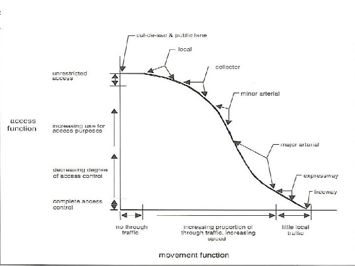
Urban Road Classification • • ARTERIAL ROADS SUB ARTERIAL COLECTOR LOCAL STREET CUL-DE-SAC PATHWAY DRIVEWAY
Road Patterns • • • Rectangular or Block patterns Radial or Star block pattern Radial or Star Circular pattern Radial or Star grid pattern Hexagonal Pattern Minimum travel Pattern
Classification of Roadways • Expressways 200 Km • National Highways 70, 548 Km • State Highways 1, 31, 899 Km • Major District Roads 4, 67, 763 Km • Rural and Other Roads 26, 50, 000 Km
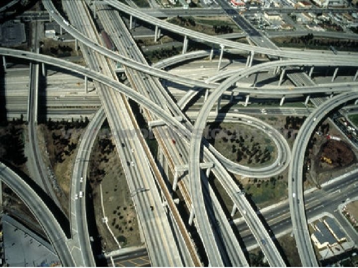
Expressways • • • Heavy traffic at high speed (120 km/hr) Land Width (90 m) Full access control Connects major points of traffic generation No slow moving traffic allowed No loading, unloading, parking.
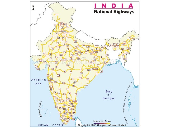
National Highway
National Highways • India has a huge network of national highways. • The national highways have a total length of 70, 548 kms. Indian highways cover 2% of the total road network of India and carry 40% of the total traffic. • The entire highway network of India is managed by the National Highway Authority of India which is responsible for development and maintenance of highways. The longest highway in India is NH 7 which stretches from Varansi in Uttar Pradesh to Kanyakumari in the southern most point of Indian mainland. • The shortest highway is NH 47 A which stretches from Ernakulam to Kochi and covers total length of 4 Kms.
Uttar Pradesh - Kanyakumari NH 7
Nagai – Trichy NH 83
State Highways • They are the arterial roads of a state, connecting up with the national highways of adjacent states, district head quarters and important cities within the state. • Total length of all SH in the country is 1, 37, 119 Kms.
Major District Roads • Important roads with in a district serving areas of production and markets , connecting those with each other or with the major highways. • India has a total of 4, 70, 000 kms of MDR.
Other district roads • Roads serving rural areas of production and providing them with outlet to market centers or other important roads like MDR or SH.
Village roads • They are roads connecting villages or group of villages with each other or to the nearest road of a higher category like ODR or MDR. • India has 26, 50, 000 kms of ODR+VR out of the total 33, 15, 231 kms of all type of roads.
Urban Road Classification • • ARTERIAL ROADS SUB ARTERIAL COLLECTOR LOCAL STREET CUL-DE-SAC PATHWAY DRIVEWAY
ARTERIAL • No frontage access, no standing vehicle, very little cross traffic. • Design Speed : 80 km/hr • Land width : 50 – 60 m • Spacing 1. 5 km in CBD(Central Business District) & 8 km or more in sparsely developed areas. • Divided roads with full or partial parking • Pedestrian allowed to walk only at intersection
SUB ARTERIAL • • • Bus stops but no standing vehicle. Less mobility than arterial. Spacing for CBD : 0. 5 km Sub-urban fringes : 3. 5 km Design speed : 60 km/hr Land width : 30 – 40 m
Collector Street • Collects and distributes traffic from local streets • Provides access to arterial roads • Located in residential, business and industrial areas. • Full access allowed. • Parking permitted. • Design speed : 50 km/hr • Land Width : 20 -30 m
Local Street • Design Speed : 30 km/hr. • Land Width : 10 – 20 m. • Primary access to residence, business or other abutting property • Less volume of traffic at slow speed • Origin and termination of trips. • Unrestricted parking, pedestrian movements. (with frontage access, parked vehicle, bus stops and no waiting restrictions)
CUL–DE- SAC • Dead End Street with only one entry access for entry and exit. • Recommended in Residential areas
HIGHWAY ALIGNMENT
Factors Influencing Highway Alignment Requirements: Ø Short Ø Easy Ø Safe Ø Economical Factors controlling alignment : 1) Obligatory points A. Obligatory points through which alignment is to pass ( bridge site, intermediate town , Mountain pass etc B. Obligatory points through which alignment should not pass. 2) Traffic 3) Geometric design 4) Economics 5) Other considerations Additional care in hill roads Stability Drainage Geometric standards of hill roads Resisting length
Factors governing alignment • Obligatory points – The location should avoid obstructions such as places of cemeteries, archeological, historical monument, public facilities like schools and hospitals, utility services. • Geometric design features – – – Facilitate easy grade and curvature Enable ruling gradient in most sections Void sudden changes in sight distance, especially near crossings Avoid sharp horizontal curves Avoid road intersections near bend or at the top or bottom of a hill
Factors governing alignment • Precautions at river and railway crossings – Bridges should be preferably be located at right angles to the river flow, not located on a horizontal curve – Crossing railway lines should avoid intersections at gradient, frequent crossing and re-crossing
Factors governing alignment • Topographical control points – The alignment, where possible should avoid passing through • • – – Marshy and low lying land with poor drainage Flood prone areas Unstable hilly features Avalanche prone areas Flat terrain-below 3% Rolling terrain -3 to 25% Mountainous terrain – above 25% A location on high ground should be preferred rather than valley to avoid cross drainage works
Factors governing alignment • Materials and constructional features – Deep cutting should be avoided – Earth work is to be balanced; quantities for filling and excavation – Alignment should preferably be through better soil area to minimize pavement thickness – Location may be near sources of embankment and pavement materials
Traffic • Trend, Direction and pattern of traffic are critical elements. • Survey should be conducted. • Desire lines based on survey should be drawn to indicate the desired pattern of traffic flow.
ECONOMIC FACTORS • • • Capital cost Maintenance Cost Operational cost Road User Cost Embankment and deep cuttings cost.
OTHER CONSIDERATIONS • Engineering feasibility • Environmental consideration • Social consideration • Political Acceptability • Monotony.
Engineering Surveys for Highway locations 1. Provisional alignment Identification ( Map study) 2. Reconnaissance survey 3. Preliminary survey 4. Final location to determine center line and detailed survey
Drawing and Report 1) 2) 3) 4) 5) 6) 7) Key map Index map Preliminary survey plans Detailed plan and longitudinal section Detailed cross section Land acquisition plans Drawings of cross drainage and other retaining structures 8) Drawings of road intersections 9) Land plans showing quarries etc
SURVEY DATA COLLECTION • • Natural and man made features. Proposed Geometric Design elements. Number of cross drainage structures. Soil characteristics Source of construction materials. Geological formation, type of rocks. Drainage
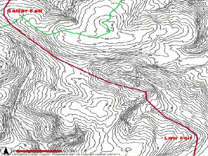
MAP STUDY • Base Map preparation ØTopographical map (So. I) Scale -1: 2, 50, 000 1: 50, 000 1: 25, 000 • Shows man made and natural features and contour lines at 15 or 30 m interval. • Shows possible alignments with obligatory points and minimum number of cross drainage structures.
RECONNAISSANCE SURVEY • Map updating – to confirm features indicated on map. • Checking for: Ø Number of cross drainage structures. Ø High Flood Level (HFL) Ø Confirming Length and value of gradient to IRC standards. Ø Soil Characteristics. Ø Geological features. Ø Proximity to source of construction materials- quarries, water sources. • Prepare a report on merits and demerits and profile map of scale 1: 50, 000.
PRELIMINARY SURVEY • Base Plan Hz Vr Ø Built up area/hilly terrain 1: 1000 1: 100 Ø Plain and rolling terrain 1: 2500 1: 250 • Establish center line • Incorporation of natural and man made features • Longitudinal and cross sectional profile (Levelling). Ø Plain Terrain` : 100 – 200 m Ø Rolling Terrain : 50 m Ø Hilly Terrain : 30 m • Other studies Ø Drainage, Hydrological, soil, Traffic and Materials. • Finalisation of the best alignment Ø Comparative analysis. Ø Choose best alignment among alternatives. Ø Design geometric elements.
DETAILED SURVEY FOR FINAL LOCATION • Transferring the alignment on to ground. • Detail Survey – levelling work for longitudinal and transverse direction. • Intervals for cross sectional levelling Ø Plain 50 – 100 m Ø Rolling 50 – 75 m Ø Built up 50 m Ø Hilly 20 m • Soil Profile
Alignment for hill roads
Alignment for hill roads • Minimum hair pin bends. • Bends should be located on stable and flat slopes. • Cross section for hair pin bends should be at intervals of 20 -25 m. • Avoid bends in valleys. • Survey for a width of ; Ø 15 m on either side of centre line in straight alignment Ø 30 m on sharp curves.
MODERN SURVEY METHODS 1) Provisional alignment Identification ( Map study) 2) Reconnaissance survey 3) Hand held GPS giving 3 D positions to an accuracy of 10 -20 m. 4) Preliminary Survey Ø Mapping of topography and relief Ø Use of aerial Photos Ø Airborne Laser Terain Mapping 5) Final location and detailed survey.
Modern Equipments for Surveying • • • EDM – Electronic Distance Measurement Auto level. Digital level. Total station. GPS – global positioning system.
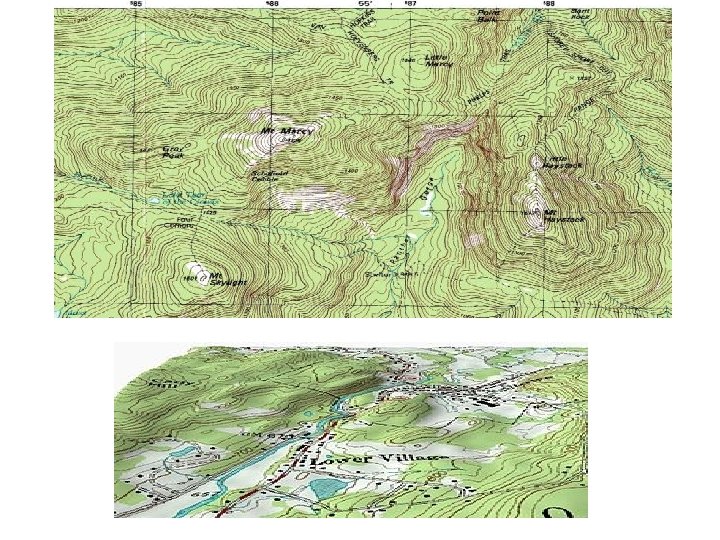
DATA FROM AERIAL SURVEY • Mosaic for longitudinal and lateral overlaps. • Control points • Examination of photos for spot levels and contour lines • Topo details • Photo interpretation for geological features, soil and drainage for the study area
GEOMETRIC DESIGN • Elements of design: – Sight distance • The length of road ahead visible to drivers – Stopping sight distance – Passing sight distance – Horizontal alignment • Super elevation rates (0. 1 for rural areas, 0. 06 for urban) • Minimum radius – Vertical alignment – Pavement design – Intersection and crossing design
Guidance for Route Selection • Straight line alignment preferred. • Avoid obstructions and frequent railway and river crossings. • Avoid landslide, erosion prone and water logged and marshy area. • Avoid alignment on clayey soil. • Alignment should aim at maintaining uniform design speed, easy grades and curvature.
Comparison of Conventional and Modern Methods of Surveying Elements of comparison Conventional Modern Maps- Base material Topo sheets RS data, Aerial Photos, Satellite Imageries Instruments Chains, Tapes, Theodolite, Dumpy levels EDM, Total Station, GPS, Auto and Digital Level, Photogrammetry. Accuracy Chain/Tape 1 in 3000 to 1 in 30, 000 Tacheometer 1 in 1000 to 1 in 10, 000 EDM/TS 1 in 10000 to 1 in 1, 000 Photogrammetry. 1 in 10000 to 1 in 1, 000 Plotting CAD Systems Software Errors Human errors Closing Errors hence re measuring is required.