Highway Engineering Lecture one Transportation Transportation engineering or


- distance earth is moved without additional compensation")
 Place FHD and LPH distances in all large loops")


 Representative Rural Arterial")
 Representative")


 Cross")


 Reason")
 Where: V = velocity (mph)")


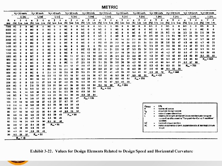
 Design radius example: assume a maximum e of 8% and design")
 For emax = 4%? Rmin = _____602________ 15(0. 04 + 0.")


(2. 5 sec) + _____(35 mph)2____ =")
![Sight Distance Example m = R(1 – cos [28. 65 S]) R m =](https://slidetodoc.com/presentation_image_h2/44b3c04941b65d03022be2e91c12cb2a/image-83.jpg "Sight Distance Example m = R(1 – cos [28. 65 S]) R m =")


- Slides: 140
Highway Engineering Lecture one Transportation ﺍﻻﻟﻜﺘﺮﻭﻧﻲ ﻧﻈﺎﻡ ﺍﻟﻤﺤﺎﺿﺮﺍﺕ
Transportation engineering or transport engineering is the application of technology and scientific principles to the planning, functional design, operation and management of facilities for any mode of transportation in order to provide for the safe, efficient, rapid, comfortable, convenient, economical, and environmentally compatible movement of people and goods (transport). ﺍﻻﻟﻜﺘﺮﻭﻧﻲ ﻧﻈﺎﻡ ﺍﻟﻤﺤﺎﺿﺮﺍﺕ
Principles of Highway Route Location Process • The basic principle for locating highways is that roadway elements such as curvature and grade must blend with each other to produce a system that provides for the easy flow of traffic at the design capacity, while meeting design criteria and safety standards. • The highway should also cause a minimal disruption to historic and archeological sites and to other land-use activities. • Environmental impact studies are therefore required in most cases before a highway location is finally agreed upon. ﺍﻻﻟﻜﺘﺮﻭﻧﻲ ﻧﻈﺎﻡ ﺍﻟﻤﺤﺎﺿﺮﺍﺕ
Highway Location Process The highway location process involves four phases: • 1. Office study of existing information. • 2. Reconnaissance survey. • 3. Preliminary location survey. • 4. Final location survey. ﺍﻻﻟﻜﺘﺮﻭﻧﻲ ﻧﻈﺎﻡ ﺍﻟﻤﺤﺎﺿﺮﺍﺕ
1. Office study of existing information • The first phase in any highway location study is the examination of all available data of the area in which the road is to be constructed. • This phase is usually carried out in the office prior to any field or photogrammetric investigation. All the available data are collected and examined. • These data can be obtained from existing engineering reports, maps, aerial photographs, and charts, which are usually available at one or more of the state’s departments of transportation, agriculture, geology, hydrology, and mining. ﺍﻻﻟﻜﺘﺮﻭﻧﻲ ﻧﻈﺎﻡ ﺍﻟﻤﺤﺎﺿﺮﺍﺕ
Data Should Be Obtained On The Following Characteristics Of The Area: • Engineering, including topography, geology, climate, and traffic volumes. • Social and demographic, including land use and zoning patterns. • Environmental, including types of wildlife; location of recreational, historic, and archeological sites; and the possible effects of air, noise, and water pollution. • Economic, including unit costs for construction and the trend of agricultural, commercial, and industrial activities. ﺍﻻﻟﻜﺘﺮﻭﻧﻲ ﻧﻈﺎﻡ ﺍﻟﻤﺤﺎﺿﺮﺍﺕ
2 - Reconnaissance Survey The object of this phase of the study is to identify several feasible routes, each within a band of a limited width of a few hundred meters. ﺍﻻﻟﻜﺘﺮﻭﻧﻲ ﻧﻈﺎﻡ ﺍﻟﻤﺤﺎﺿﺮﺍﺕ
Feasible routes are identified by a stereoscopic examination of the aerial photographs, taking into consideration factors such as: • Terrain and soil conditions. • Serviceability of route to industrial and population areas. • Crossing of other transportation facilities, such as rivers, railroads, and other highways. • Directness of route. ﺍﻻﻟﻜﺘﺮﻭﻧﻲ ﻧﻈﺎﻡ ﺍﻟﻤﺤﺎﺿﺮﺍﺕ
3 - Preliminary Location Survey During this phase of the study, the positions of the feasible routes are set as closely as possible by establishing all the control points and determining preliminary vertical and horizontal alignments for each. Preliminary alignments are used to evaluate the economic and environmental feasibility of the alternative routes. ﺍﻻﻟﻜﺘﺮﻭﻧﻲ ﻧﻈﺎﻡ ﺍﻟﻤﺤﺎﺿﺮﺍﺕ
4 - Final Location Survey The final location survey is the detailed layout of the selected route, during which time the final horizontal and vertical alignments are determined and the final positions of structures and drainage channels are also determined. ﺍﻻﻟﻜﺘﺮﻭﻧﻲ ﻧﻈﺎﻡ ﺍﻟﻤﺤﺎﺿﺮﺍﺕ
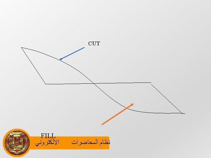
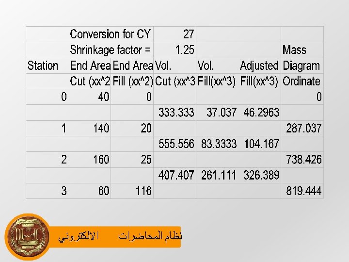
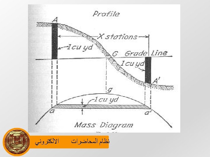
Earthwork Analysis • Average End Area Method • Consideration for shrinkage • Balance line Considerations • Limit of Freehaul (LFD) • Limit of Profitable Haul (LFH) ﺍﻻﻟﻜﺘﺮﻭﻧﻲ ﻧﻈﺎﻡ ﺍﻟﻤﺤﺎﺿﺮﺍﺕ
Special Terms • Free haul distance (FHD)- distance earth is moved without additional compensation • Limit of Profitable Haul (LPH) - distance beyond which it is more economical to borrow or waste than to haul from the project • Overhaul – volume of material (Y) moved X Stations beyond Freehaul, measured in sta – yd 3, or sta- m 3 • Borrow – material purchased outside of project • Waste – excavated material not used in project ﺍﻻﻟﻜﺘﺮﻭﻧﻲ ﻧﻈﺎﻡ ﺍﻟﻤﺤﺎﺿﺮﺍﺕ
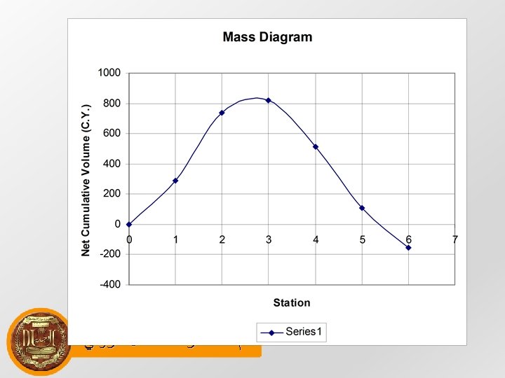
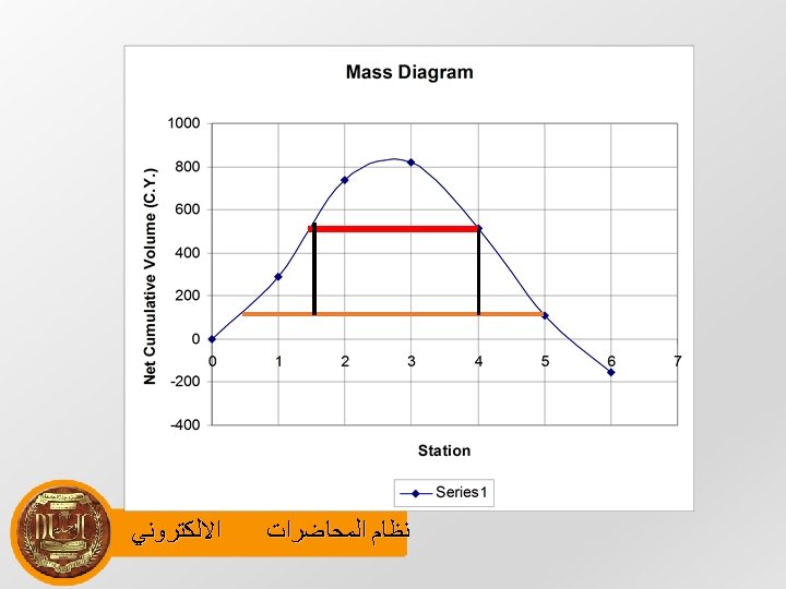
Mass Diagram Development • 1) Place FHD and LPH distances in all large loops • 2) Place other Balance lines to minimize cost of movement (theoretical) • 3) Calculate borrow, waste, and overhaul in all loops • 4) Identify stations where each of the above occur ﺍﻻﻟﻜﺘﺮﻭﻧﻲ ﻧﻈﺎﻡ ﺍﻟﻤﺤﺎﺿﺮﺍﺕ
Functional Classification Different classification schemes have been applied for different purposes in different rural and urban regions. Classification by Design Type: Highway Location and Design Procedures Classification by Route Numbering: Traffic Operations Administrative classification: Highway Funding Functional classification: Transportation Planning and Design ASSHTO Green Book is based on the functional classification. One of the first steps in the design process is determining the functional classification of a facility. ﺍﻻﻟﻜﺘﺮﻭﻧﻲ ﻧﻈﺎﻡ ﺍﻟﻤﺤﺎﺿﺮﺍﺕ
Functional Classification is the process by which streets and highways are grouped into classes according to the character of traffic service that they are intended to provide. There are three functional classes: Arterials including freeways Collectors Local Roads Functional System Services Provided Arterial Provides the highest level of service at the greatest speed for the longest uninterrupted distance, with some degree of access control. Collector Provides a less highly developed level of service at a lower speed for shorter distances by collecting traffic from local roads and connecting them with arterials. Local Consists of all roads not defined as arterials or collectors; primarily provides access to land with little or no through movement. ﺍﻻﻟﻜﺘﺮﻭﻧﻲ ﻧﻈﺎﻡ ﺍﻟﻤﺤﺎﺿﺮﺍﺕ
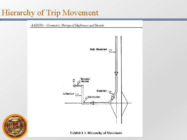
Trip Generation, Collection and Distribution ﺍﻻﻟﻜﺘﺮﻭﻧﻲ ﻧﻈﺎﻡ ﺍﻟﻤﺤﺎﺿﺮﺍﺕ
Mobility and Accessibility of Highway Facilities § Arterials provide a high level of mobility and a greater degree of access control § Collector roadways provide a balance between mobility and land access Arterials § Local facilities provide a high level of access to adjacent properties but a low level of mobility ﺍﻻﻟﻜﺘﺮﻭﻧﻲ ﻧﻈﺎﻡ ﺍﻟﻤﺤﺎﺿﺮﺍﺕ Collectors Local Roads
Mobility and Accessibility of Highway Facilities Rural Highway Network Suburban Highway Network ﺍﻻﻟﻜﺘﺮﻭﻧﻲ ﻧﻈﺎﻡ ﺍﻟﻤﺤﺎﺿﺮﺍﺕ Urban Street Network
Roles of Functional Classification in Design § AASHTO Green Book establishes the relationships between highway functional classification and design criteria. State, county, and city highway design manuals relate design criteria to highway functional classification. § Once the functional classification of a particular roadway has been established, so has the allowable range of design speed. With the allowable range of design speed defined, the principal limiting design parameters associated with horizontal and vertical alignment are also defined. § Also, the determination of functional classification establishes the basic roadway cross section in terms of lane width, shoulder width, type and width of median area, and other major design features. ﺍﻻﻟﻜﺘﺮﻭﻧﻲ ﻧﻈﺎﻡ ﺍﻟﻤﺤﺎﺿﺮﺍﺕ
Definition of Urban and Rural Areas § Urban or rural = f (density and types of land use, density of street and highway networks, nature of travel patterns, and the way in which these elements are related) § Urban areas are those places with a population of 5000 or more. 50, 000 or more Urbanized areas 5, 000 – 50, 000 Small urban areas § Rural areas are those areas outside the boundaries of urban areas. ﺍﻻﻟﻜﺘﺮﻭﻧﻲ ﻧﻈﺎﻡ ﺍﻟﻤﺤﺎﺿﺮﺍﺕ
Representative Arterials Representative Freeway (I-476/US Route 1 Interchange, Montgomery County, PA) Representative Rural Arterial ﻧﻈﺎﻡ ﺍﻻﻟﻜﺘﺮﻭﻧﻲ ﺍﻟﻤﺤﺎﺿﺮﺍﺕ (Taconic State Parkway, NY) Representative Urban Arterial (Windsor, CT) Representative Rural Arterial (Rt 58, CT)
Representative Collectors and Local Roads Representative Collector in a Residential Area (Greenbelt, MD) Representative Rural Collector ﻧﻈﺎﻡ ﺍﻻﻟﻜﺘﺮﻭﻧﻲ ﺍﻟﻤﺤﺎﺿﺮﺍﺕ (Easton, CT) Representative Urban Collector (Lambertville, NJ) Representative Local Street (Montgomery Co. , MD)
Current Highway Functional Classifications Functional System Percent of Total Mileage Interstate Percent of Total Travel 1. 2 22. 8 . 2 6. 2 Other Principal Arterial 3. 8 24. 3 Minor Arterial 5. 7 18. 4 Major Collector 11. 1 7. 8 Minor Collector 7. 2 2. 1 Collector 2. 2 5. 3 Local 68. 6 13. 1 Total 100 Other Freeway/Expressway ﺍﻻﻟﻜﺘﺮﻭﻧﻲ ﻧﻈﺎﻡ ﺍﻟﻤﺤﺎﺿﺮﺍﺕ
Land Use, Urban Sprawl, Highway Classifications § Traffic service patterns on a roadway and the roadway’s function can change over time due to change of land use and urban sprawl. § The functional classification of a highway may be upgraded to a higher lever to reflect the change of traffic service patterns. § Road functions can change over time. Figure (a) shows a new road through the country. Figure (b) shows the first residences along the road. Figure (c) shows suburbanization and the need for mitigation. ﺍﻻﻟﻜﺘﺮﻭﻧﻲ ﻧﻈﺎﻡ ﺍﻟﻤﺤﺎﺿﺮﺍﺕ
Design Standards and Highway Classifications § Functional Classification of a highway facility is often related to the “level of development” or the design criteria that should be applied. § The relationship shown here represents the State of Washington’s table for the relationship. Functional Class Design Criteria Interstate New Construction/Reconstruction Standards Principal Arterial New Construction/Reconstruction Standards Minor Arterial 3 R Standards Collector ﺍﻻﻟﻜﺘﺮﻭﻧﻲ Maintenance of Structural Integrity and Operational Safety. ﻧﻈﺎﻡ ﺍﻟﻤﺤﺎﺿﺮﺍﺕ
CROSS SECTION ELEMNTS Roadway - The portion of a highway, including shoulders for vehicular use. Traveled way movement of ﺍﻻﻟﻜﺘﺮﻭﻧﻲ The portion of the roadway for the vehicles, exclusive of shoulders. ﻧﻈﺎﻡ ﺍﻟﻤﺤﺎﺿﺮﺍﺕ
PAVEMENT Surface Type = f(traffic volume/composition, design speed, soil conditions, weather, materials, etc) Cross Slope Undivided traveled ways on tangent or flat curve a crown or high point in the middle and a cross slope downward toward both edges Unidirectional cross slopes for ramps and superelevated ﻧﻈﺎﻡ ﺍﻟﻤﺤﺎﺿﺮﺍﺕ section ﺍﻻﻟﻜﺘﺮﻭﻧﻲ
PAVEMENT Cross Slope Surface Type High Low Range in cross slope rate % 1. 5 – 2 2 -6 Skid Resistance Skid resistance should be a consideration in the design of all new construction and major reconstruction projects. Wet surface has a low skid resistance than dry surface. ﺍﻻﻟﻜﺘﺮﻭﻧﻲ ﻧﻈﺎﻡ ﺍﻟﻤﺤﺎﺿﺮﺍﺕ Lane Width 2. 7 – 3. 6 m
SHOULDERS Definition A shoulder is the portion of the roadway contiguous with the traveled way that accommodate stopped vehicles, emergency use, and lateral support of subbase, base and surface courses. Shoulder Graded Width Usable Width ETW – the intersection of the shoulder slope and the foreslope planes. see Exhibit 4 -5 for the range. Width of Shoulder 0. 6 – 3 m Where roadside barriers, walls, or other vertical elements are present, a minimum of 0. 6 m should be provided from the outer edge of the usable shoulder. For low-volume roads, 1. 2 m ﺍﻻﻟﻜﺘﺮﻭﻧﻲ ﻧﻈﺎﻡ ﺍﻟﻤﺤﺎﺿﺮﺍﺕ
SHOULDERS Shoulder Cross Sections Concrete shoulder Gravel shoulder Turf Shoulder 2 -6% 4 -6% 6 -8% Break of cross slope grades 8% rounded Shoulder Stability Stable to support occasional vehicle loads in all kinds of weather without rutting Shoulder Contrast Desirable to have shoulders with color and texture different from those on traveled way Edge lines should be provided when shoulder use by bikes are expected. Turnouts ﺍﻻﻟﻜﺘﺮﻭﻧﻲ Turnouts to replace shoulders are needed for emergency stops in locations where ﺍﻟﻤﺤﺎﺿﺮﺍﺕ ﻧﻈﺎﻡ shoulders are not feasible.
HORIZONTAL CLEARANCE § Horizontal clearance to obstructions should be considered. AASHTO Roadside Design Guide should be used for it. § A minimum of 3. 0 m clear zone should be provided for lowspeed rural collector and rural local roads. § The clear zone for freeways, rural arterials, and high-speed rural collectors should be determined using AASHTO Roadside Guide. § Urban streets, collectors, and arterials should have a min offset distance of 500 mm beyond the face of the curb. ﺍﻻﻟﻜﺘﺮﻭﻧﻲ ﻧﻈﺎﻡ ﺍﻟﻤﺤﺎﺿﺮﺍﺕ
CURBS § Type and location of curbs affects driver behavior and the safety and utility of a highway. § Curbs are used for drainage control, roadway edge delineation, ROW reduction, aesthetics, delineation of ped walkways, reduction of maintenance operations, and assistance in orderly roadside development. § Curbs on all low-speed urban highways. Caution on high-speed rural highways. When curbs are used on high-speed highways, they are placed at the outside edge of the shoulder. ﺍﻻﻟﻜﺘﺮﻭﻧﻲ ﻧﻈﺎﻡ ﺍﻟﻤﺤﺎﺿﺮﺍﺕ
CURBS Configuration Two types of curbs: vertical and sloping curbs. Vertical curbs discourage vehicles from leaving the roadway 150 mm – 200 mm height. No use on freeways and high-speed highways Sloping curbs Vehicles can cross the curbs. They are mountable under emergency conditions. Extruded curbs are sloped curbs. The slope of the curb face is 1: 1. Height 150 mm Median edges or outer edge of shoulder ﺍﻻﻟﻜﺘﺮﻭﻧﻲ ﻧﻈﺎﻡ ﺍﻟﻤﺤﺎﺿﺮﺍﺕ
CURBS Configuration Gutter section may be designed along with curbs. Width of a gutter is 0. 3 – 1. 8 m. Curb Placement Curbs may be placed at the edge of the traveled way for lowspeed urban streets, preferably with the offset of 0. 3 – 0. 6 m. Vertical curbs cannot be placed along freeways or highways ﺍﻻﻟﻜﺘﺮﻭﻧﻲ ﻧﻈﺎﻡ ﺍﻟﻤﺤﺎﺿﺮﺍﺕ speed
DRAINAGE CHANNELS AND SIDESLOPES Drainage Channels Drainage channels collect and convey surface water from the highway ROW. Drainage design often involve flat sideslopes, broad drainage channels, and literal warping and rounding. Drainage channels should be designed along with the sideslopes Drainage channels have roadside channels, toe-of-slope channels, intercepting channels, and flumes. ﺍﻻﻟﻜﺘﺮﻭﻧﻲ ﻧﻈﺎﻡ ﺍﻟﻤﺤﺎﺿﺮﺍﺕ
DRAINAGE CHANNELS AND SIDESLOPES Sideslopes should be designed to ensure roadway stability and to provide a reasonable opportunity for recovery for an out-of-control vehicle. Three regions should be considered for the design of sideslopes: the top of the slope (hinge point), the foreslope, and the toe of the slope (intersection of the foreslope with level ground or with a backslope forming a ditch) The hinge point and the toe of the slope should be rounded ﺍﻻﻟﻜﺘﺮﻭﻧﻲ ﻧﻈﺎﻡ ﺍﻟﻤﺤﺎﺿﺮﺍﺕ
TRAFFIC BARRIERS Traffic barriers are used to prevent vehicles leaving the traveled way from hitting an object that has greater crash severity potential than the barrier itself. There are two types of traffic barriers: longitudinal barriers and crash cushions. Longitudinal Barriers Redirect errant vehicles. Along the roadside and in median Flexible, Semi-rigid, rigid = f(deflection) Flexible: dynamic deflection, resistance from the tensile force Semi-rigid: flexure and tensile ﺍﻻﻟﻜﺘﺮﻭﻧﻲ ﺍﻟﻤﺤﺎﺿﺮﺍﺕ ﻧﻈﺎﻡ Rigid: no deflection, energy dissipated by deformation.
TRAFFIC BARRIERS Longitudinal Barriers Roadside Barriers along Shield vehicles from obstacles or slopes located either side of a roadway. ensure that Located beyond the edge of the shoulder to the full shoulder width may be used. Median Barriers vehicle crossing opposite directions. ﺍﻻﻟﻜﺘﺮﻭﻧﻲ of 15 m or less Minimize the possibility of an errant into the path of traffic traveling in Used for medians that separate traveled ways at ﺍﻟﻤﺤﺎﺿﺮﺍﺕ ﻧﻈﺎﻡ elevations or outer separations different where the frontage roads carry
TRAFFIC BARRIERS Longitudinal Barriers Bridge Railings from falling extension of a bridge. Prevent vehicles, pedestrians, or cyclists off the structure. It is a structure max. Its design = f(geometric highway, design load, allowable material stress) end treatment A roadside barrier is often used to tie with bridge railing. If roadside barrier is not used, with crash cushions should be considered. ﺍﻻﻟﻜﺘﺮﻭﻧﻲ Crash Cushions ﺍﻟﻤﺤﺎﺿﺮﺍﺕ ﻧﻈﺎﻡ Decelerate errant vehicles to a stop.
MEDIANS A portion of a highway separating opposing directions of the travel way. Its width is measured from the edge of traveled way to the edge of another traveled way and varies from 1. 2 to 24 m. Depressed Median: Raised Median: movements should be Flush median two ﺍﻻﻟﻜﺘﺮﻭﻧﻲ Median side slope 1: 6 on freeways. Drainage inlets should be designed. Arterial streets where left-turn regulated. Urban Arterials. Now converting flush media to way left turn lanes are commonly accepted. ﻧﻈﺎﻡ ﺍﻟﻤﺤﺎﺿﺮﺍﺕ
FRONTAGE ROADS Frontage roads control access to the arterials, act as a street road serving adjoining properties, or maintain circulation of traffic on each side of the arterial. A minimum spacing of about 50 m between the arterial and the frontage roads should be provided in urban area. Where offramps join a two-way frontage road, the potential for wrong way entry is increased. Connection between the arterial and frontage road are important design element urban highway ﺍﻻﻟﻜﺘﺮﻭﻧﻲ in an ﺍﻟﻤﺤﺎﺿﺮﺍﺕ ﻧﻈﺎﻡ system
OUTER SEPARATIONS The area between the traveled way of a through-traffic roadway and a frontage road or street is outer separation. It is the buffer between the arterial and the frontage road and provides space for a shoulder for the through roadway and ramp connections to or from the through facility. The cross section and treatment of an outer separation depend on the width and the type of arterial and the frontage road. See Exhibit 4 -13 on Page 348. ﺍﻻﻟﻜﺘﺮﻭﻧﻲ ﻧﻈﺎﻡ ﺍﻟﻤﺤﺎﺿﺮﺍﺕ
NOISE CONTROL Motor vehicles generate traffic noise. Designers should design noise barrier or sound walls to minimize the radiation of noise into noise-sensitive areas along the highway. Before the sound walls design, designers need to evaluate existing or potential noise levels and estimate the effectiveness of reducing noise using sound walls. A-scale on a standard sound level meter - db. A An example of noise evaluation will be provided here. Noise reduction designs: depressed highways, sound barriers, ﻧﻈﺎﻡ ﺍﻟﻤﺤﺎﺿﺮﺍﺕ natural ﺍﻻﻟﻜﺘﺮﻭﻧﻲ barriers (trees)
ROADSIDE CONTROL Roadside control is the measure to control access from or to a highway. Driveways: Design should be taken carefully on the location of driveways on highways. Driveways used for right turns are desirable where cross section includes a curbed median or a flush median and median barrier. Driveways = f(ROW, land use, functional classification of highway) Guidelines for Driveway Design and Location is a good reference book. Driveway regulations control ROW encroachment, driveway location, driveway design, sight distance, drainage, use of curbs, ﺍﻻﻟﻜﺘﺮﻭﻧﻲ ﻧﻈﺎﻡ ﺍﻟﻤﺤﺎﺿﺮﺍﺕ parking, setback, lighting, and signing.
ROADSIDE CONTROL Mailboxes: Design should be taken carefully on the location of driveways on highways. Driveways used for right turns are desirable where cross section includes a curbed median or a flush median and median barrier. Driveways = f(ROW, land use, functional classification of highway) Guidelines for Driveway Design and Location is a good reference book. Driveway regulations control ROW encroachment, driveway location, driveway design, sight distance, drainage, use of curbs, parking, setback, lighting, and signing. ﺍﻻﻟﻜﺘﺮﻭﻧﻲ ﻧﻈﺎﻡ ﺍﻟﻤﺤﺎﺿﺮﺍﺕ
PEDESTRIAN FACILITIES Sidewalks provided an integral part of city streets but are rarely in rural areas. 1. 2 m to Sidewalk widths in residential areas vary from 2. 4 m. or though Sidewalks should be constructed along any street highway not provided with shoulders, even pedestrian traffic may be light. Pedestrian facilities such as sidewalks should be designed to accommodate people with disabilities. ﺍﻻﻟﻜﺘﺮﻭﻧﻲ ﻧﻈﺎﻡ ﺍﻟﻤﺤﺎﺿﺮﺍﺕ AASHTO Guide for the Planning, Design, and
PEDESTRIAN FACILITIES Grade-Separated Pedestrian Crossings and A grade-separated pedestrian facility allows pedestrian vehicles to cross at different levels, either over or under a roadway. Pedestrian overcrossings are preferable to undercrossings Pedestrian ramps should be provided at all pedestrian separation structures. Walkways for pedestrian separations should have at least ﻧﻈﺎﻡ ﺍﻟﻤﺤﺎﺿﺮﺍﺕ 2. 4 m. ﺍﻻﻟﻜﺘﺮﻭﻧﻲ
PEDESTRIAN FACILITIES Sidewalk Curb Ramps When designing a project that includes curbs and adjacent sidewalks, proper attention should be given to the needs of persons with disabilities whose means of mobility are dependent on wheelchairs and other devices. Factors for sidewalk curb ramps are : § § § § § sidewalk width sidewalk location with respect to the back face of curb height and width of curb cross section design turning radius and length of curve along the curb face angle of street intersections planned or existing location of sign and signal control devices storm water inlets and public service utilities potential sight obstructions, street width, border width, roadway grade in combination with the grades of the sidewalk, curb, ramps, and gutter. ﺍﻻﻟﻜﺘﺮﻭﻧﻲ ﻧﻈﺎﻡ ﺍﻟﻤﺤﺎﺿﺮﺍﺕ
PEDESTRIAN FACILITIES Sidewalk Curb Ramps Basic curb ramp types have been established and used in accordance with the geometric characteristics of each intersection. Width min = 0. 9 m and 8. 33% max grade Cross slopes on adjacent sidewalks should be no greater than 2%. A level landing area is required at the top of each curb ramp. The location of the sidewalk curb ramp should be carefully coordinated with respect to the pedestrian crosswalk lines. Curb ramps for persons wit disabilities are not limited to intersections and marked crosswalks. They can also be needed at pedestrian concentrations such as loading islands and midblock crossings. ﺍﻻﻟﻜﺘﺮﻭﻧﻲ ﻧﻈﺎﻡ ﺍﻟﻤﺤﺎﺿﺮﺍﺕ
PEDESTRIAN FACILITIES Sidewalk Curb Ramps Each intersections will differ with respect to the intersection angles, turning roadway widths, size of islands, drainage inlets, traffic control devices, and other factors. An appropriate plan should be prepared that indicates all of the desired geometries, locations of the ramp. The location of ramp governs the pedestrian crosswalk patterns, stop bar locations, and regulatory signs. ﺍﻻﻟﻜﺘﺮﻭﻧﻲ ﻧﻈﺎﻡ ﺍﻟﻤﺤﺎﺿﺮﺍﺕ
BICYCLE FACILITIES AASHTO Guide for the Development of Bicycle Facilities “Design of Bicycle and Pedestrian Facilities” Training course for Caltrans Engineers ﺍﻻﻟﻜﺘﺮﻭﻧﻲ ﻧﻈﺎﻡ ﺍﻟﻤﺤﺎﺿﺮﺍﺕ
BUS TURNOUTS Bus turnouts serve to remove the bus from the traveled way. The location and design of the turnouts should provide ready access in the safest and most efficient manner practical. Freeway Bus Its objective is to design the turnout to allow buses to Turnout decelerate, stand accelerate in the area clear of and separated from the traveled way Arterial Bus. A deceleration lane or taper to permit easy entrance to Turnout the loading area, a standing space sufficiently long to accommodate the maximum number of vehicles expected to occupy the space at one time, and a merging lane to enable easy reentry into the traveled way. AASHTO Guidelines for the Location and Design of Bus Stops ﺍﻻﻟﻜﺘﺮﻭﻧﻲ ﻧﻈﺎﻡ ﺍﻟﻤﺤﺎﺿﺮﺍﺕ
BUS TURNOUTS Park and Ride Located adjacent to the streets or highways and visible Facilities to commuters whom they are intended to attract. PR lot = f(design volume, land area. Size and number of other parking lots in the area) 20 - 60 spaces. A drop-off and a pick up facilities are needed. Free parking One exit and entrance / 500 spaces more on AASHTO Guide for the Design of Parking-and. Ride Facilities ﺍﻻﻟﻜﺘﺮﻭﻧﻲ ﻧﻈﺎﻡ ﺍﻟﻤﺤﺎﺿﺮﺍﺕ
ON-STREET PARKING When on-street parking is considered, parallel parking should be preferred. A problem is the uneven distribution of off-street parking facilities within urban CBD and the lack of off-street facilities in urban neighborhood commercial area. Exhibit 4 -31 shows parking lane transition at intersection ﺍﻻﻟﻜﺘﺮﻭﻧﻲ ﻧﻈﺎﻡ ﺍﻟﻤﺤﺎﺿﺮﺍﺕ
Horizontal Alignment • Design based on appropriate relationship between design speed and curvature and their interaction with side friction and superelevation • Along circular path, inertia causes the vehicle to attempt to continue in a straight line • Superelevation and friction between tire and roadway provides a force to offset the vehicle’s inertia; this force is directed toward the center of curvature (often called centrifugal or centripetal force) ﺍﻻﻟﻜﺘﺮﻭﻧﻲ ﻧﻈﺎﻡ ﺍﻟﻤﺤﺎﺿﺮﺍﺕ 68
Horizontal Alignment 1. Tangents 2. Curves 3. Transitions Curves require superelevation (next lecture) Reason for super: banking of curve, retard sliding, allow more uniform speed, also allow use of smaller radii curves (less land) ﺍﻻﻟﻜﺘﺮﻭﻧﻲ ﻧﻈﺎﻡ ﺍﻟﻤﺤﺎﺿﺮﺍﺕ 69
Radius Calculation Rmin = ___V 2______ 15(e + f) Where: V = velocity (mph) e = superelevation f = friction (15 = gravity and unit conversion) ﺍﻻﻟﻜﺘﺮﻭﻧﻲ ﻧﻈﺎﻡ ﺍﻟﻤﺤﺎﺿﺮﺍﺕ 70
Radius Calculation • • • Rmin related to max. f and max. e allowed Rmin use max e and max f (defined by AASHTO, DOT, and graphed in Green Book) and design speed f is a function of speed, roadway surface, weather condition, tire condition, and based on comfort – drivers brake, make sudden lane changes and changes within a lane when acceleration around a curve becomes “uncomfortable” AASHTO: 0. 5 @ 20 mph with new tires and wet pavement to 0. 35 @ 60 mph f decreases as speed increases (less tire/pavement contact) ﺍﻻﻟﻜﺘﺮﻭﻧﻲ ﻧﻈﺎﻡ ﺍﻟﻤﺤﺎﺿﺮﺍﺕ 71
Max e • Controlled by 4 factors: • Climate conditions (amount of ice and snow) • Terrain (flat, rolling, mountainous) • Frequency of slow moving vehicles who might be influenced by high superelevation rates • Highest in common use = 10%, 12% with no ice and snow on low volume gravel-surfaced roads • 8% is logical maximum to minimized slipping by stopped vehicles ﺍﻻﻟﻜﺘﺮﻭﻧﻲ ﻧﻈﺎﻡ ﺍﻟﻤﺤﺎﺿﺮﺍﺕ 72
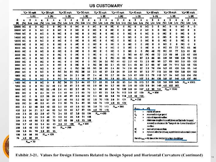
ﺍﻻﻟﻜﺘﺮﻭﻧﻲ ﻧﻈﺎﻡ ﺍﻟﻤﺤﺎﺿﺮﺍﺕ Source: A Policy on Geometric Design of Highways and Streets (The Green Book). Washington, DC. American Association of State Highway and Transportation Officials, 2001 4 th Ed. 73
Radius Calculation (Example) Design radius example: assume a maximum e of 8% and design speed of 60 mph, what is the minimum radius? fmax = 0. 12 (from Green Book) Rmin = _____602________ 15(0. 08 + 0. 12) Rmin = 1200 feet ﺍﻻﻟﻜﺘﺮﻭﻧﻲ ﻧﻈﺎﻡ ﺍﻟﻤﺤﺎﺿﺮﺍﺕ 76
Radius Calculation (Example) For emax = 4%? Rmin = _____602________ 15(0. 04 + 0. 12) Rmin = 1, 500 feet ﺍﻻﻟﻜﺘﺮﻭﻧﻲ ﻧﻈﺎﻡ ﺍﻟﻤﺤﺎﺿﺮﺍﺕ 77
Curve Types 1. Simple curves with spirals 2. Broken Back – two curves same direction (avoid) 3. Compound curves: multiple curves connected directly together (use with caution) go from large radii to smaller radii and have R(large) < 1. 5 R(small) 4. Reverse curves – two curves, opposite direction (require separation typically for superelevation attainment) ﺍﻻﻟﻜﺘﺮﻭﻧﻲ ﻧﻈﺎﻡ ﺍﻟﻤﺤﺎﺿﺮﺍﺕ 78
Important Components of Simple Circular Curve See: ftp: //165. 206. 203. 34/design/dmanual/02 a-01. pdf 1. 2. 3. 4. See handout PC, PI, PT, E, M, and L = 2( )R( )/360 T = R tan ( /2) ﺍﻻﻟﻜﺘﺮﻭﻧﻲ ﻧﻈﺎﻡ ﺍﻟﻤﺤﺎﺿﺮﺍﺕ Source: Iowa DOT Design Manual 79
Sight Distance for Horizontal Curves • Location of object along chord length that blocks line of sight around the curve • m = R(1 – cos [28. 65 S]) R Where: m = line of sight S = stopping sight distance R = radius ﺍﻻﻟﻜﺘﺮﻭﻧﻲ ﻧﻈﺎﻡ ﺍﻟﻤﺤﺎﺿﺮﺍﺕ 80
Sight Distance Example A horizontal curve with R = 800 ft is part of a 2 -lane highway with a posted speed limit of 35 mph. What is the minimum distance that a large billboard can be placed from the centerline of the inside lane of the curve without reducing required SSD? Assume p/r =2. 5 and a = 11. 2 ft/sec 2 SSD = 1. 47 vt + _____v 2____ 30(__a___ G) 32. 2 ﺍﻻﻟﻜﺘﺮﻭﻧﻲ ﻧﻈﺎﻡ ﺍﻟﻤﺤﺎﺿﺮﺍﺕ 81
Sight Distance Example SSD = 1. 47(35 mph)(2. 5 sec) + _____(35 mph)2____ = 246 feet 30(__11. 2___ 0) 32. 2 ﺍﻻﻟﻜﺘﺮﻭﻧﻲ ﻧﻈﺎﻡ ﺍﻟﻤﺤﺎﺿﺮﺍﺕ 82
Sight Distance Example m = R(1 – cos [28. 65 S]) R m = 800 (1 – cos [28. 65 {246}]) = 9. 43 feet 800 (in radians not degrees) ﺍﻻﻟﻜﺘﺮﻭﻧﻲ ﻧﻈﺎﻡ ﺍﻟﻤﺤﺎﺿﺮﺍﺕ 83
Horizontal Curve Example • Deflection angle of a 4º curve is 55º 25’, PC at station 238 + 44. 75. Find length of curve, T, and station of PT. • D = 4º • = 55º 25’ = 55. 417º • D = _5729. 58_ R = _5729. 58_ = 1, 432. 4 ft R 4 ﺍﻻﻟﻜﺘﺮﻭﻧﻲ ﻧﻈﺎﻡ ﺍﻟﻤﺤﺎﺿﺮﺍﺕ 84
Horizontal Curve Example • D = 4º • = 55. 417º • R = 1, 432. 4 ft • L = 2 R = 2 (1, 432. 4 ft)(55. 417º) = 1385. 42 ft 360 ﺍﻻﻟﻜﺘﺮﻭﻧﻲ ﻧﻈﺎﻡ ﺍﻟﻤﺤﺎﺿﺮﺍﺕ 85
Horizontal Curve Example • D = 4º • = 55. 417º • R = 1, 432. 4 ft • L = 1385. 42 ft • T = R tan = 1, 432. 4 ft tan (55. 417) = 752. 30 ft 2 2 ﺍﻻﻟﻜﺘﺮﻭﻧﻲ ﻧﻈﺎﻡ ﺍﻟﻤﺤﺎﺿﺮﺍﺕ 86
Horizontal Curve Example Stationing goes around horizontal curve. What is station of PT? PC = 238 + 44. 75 L = 1385. 42 ft = 13 + 85. 42 Station at PT = (238 + 44. 75) + (13 + 85. 42) = 252 + 30. 17 ﺍﻻﻟﻜﺘﺮﻭﻧﻲ ﻧﻈﺎﻡ ﺍﻟﻤﺤﺎﺿﺮﺍﺕ 87
Suggested Steps on Horizontal Design 1. Select tangents, PIs, and general curves make sure you meet minimum radii 2. Select specific curve radii/spiral and calculate important points (see lab) using formula or table (those needed for design, plans, and lab requirements) 3. Station alignment (as curves are encountered) 4. Determine super and runoff for curves and put in table (see next lecture for def. ) 5. Add information to plans ﺍﻻﻟﻜﺘﺮﻭﻧﻲ ﻧﻈﺎﻡ ﺍﻟﻤﺤﺎﺿﺮﺍﺕ 88
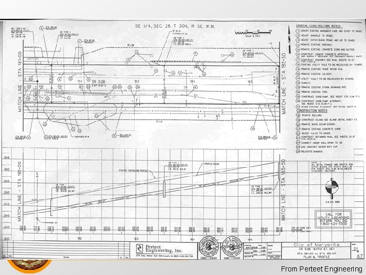
Concepts • Alignment is a 3 D problem broken down into two 2 D problems • Horizontal Alignment (plan view) • Vertical Alignment (profile view) • Stationing • Along horizontal alignment • 12+00 = 1, 200 ft. ﺍﻻﻟﻜﺘﺮﻭﻧﻲ ﻧﻈﺎﻡ ﺍﻟﻤﺤﺎﺿﺮﺍﺕ
Stationing Horizontal Alignment Vertical Alignment ﺍﻻﻟﻜﺘﺮﻭﻧﻲ ﻧﻈﺎﻡ ﺍﻟﻤﺤﺎﺿﺮﺍﺕ
Vertical Alignment • Objective: • Determine elevation to ensure • Proper drainage • Acceptable level of safety • Primary challenge • Transition between two grades • Vertical curves Sag Vertical Curve G 1 G 2 ﺍﻻﻟﻜﺘﺮﻭﻧﻲ ﺍﻟﻤﺤﺎﺿﺮﺍﺕ Crest Vertical Curve ﻧﻈﺎﻡ G 1 G 2
Vertical Curve Fundamentals • Parabolic function • Constant rate of change of slope • Implies equal curve tangents • y is the roadway elevation x stations (or feet) from the beginning of the curve ﺍﻻﻟﻜﺘﺮﻭﻧﻲ ﻧﻈﺎﻡ ﺍﻟﻤﺤﺎﺿﺮﺍﺕ
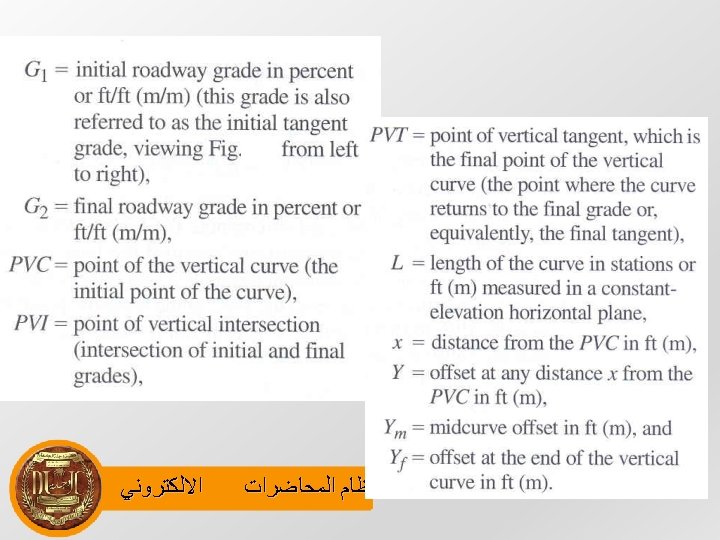
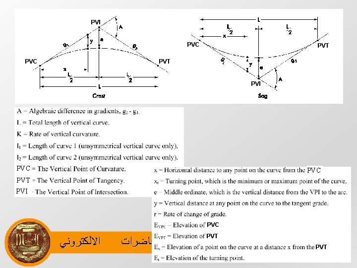
Vertical Curve Fundamentals Choose Either: • G 1, G 2 in decimal form, L in feet PVC G 1 PVI • G 1, G 2 in percent, L in stations δ G 2 PVT L/2 L x Where: G 1: Initial roadway grade( initial tangent grade) G 2: Final roadway grade A: Absolute value of the difference in grades L: Length of vertical curve measured in a horizontal plane PVC: Initial point of the vertical curve ﺍﻻﻟﻜﺘﺮﻭﻧﻲ ﺍﻟﻤﺤﺎﺿﺮﺍﺕ ﻧﻈﺎﻡ PVI: Point of vertical intersection ( intersection of initial and final grades) PVT: Final point of the vertical curve
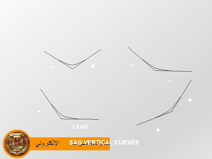
• Vertical curves are almost arranged such that half of the curve length is positioned before the PVI and half after and are referred as equal tangent vertical curves. • A circular curve is used to connect the horizontal straight stretches of road, a parabolic curve is usually used to connect gradients in the profile alignment. ﺍﻻﻟﻜﺘﺮﻭﻧﻲ ﻧﻈﺎﻡ ﺍﻟﻤﺤﺎﺿﺮﺍﺕ
• It provides a constant rate of change of slope and implies equal curve lengths. + + - + Level - + ﺍﻻﻟﻜﺘﺮﻭﻧﻲ CREST VERTICAL CURVES ﺍﻟﻤﺤﺎﺿﺮﺍﺕ ﻧﻈﺎﻡ -
Vertical Curve • For a vertical curve, the general form of the parabolic equation is; Y = ax 2 + bx + c where, ‘y’ is the roadway elevation of the curve at a point ‘x’ along 1 the curve from the beginning of the vertical curve (PVC). ‘C’ is the elevation of the PVC since x=0 corresponds the PVC ﺍﻻﻟﻜﺘﺮﻭﻧﻲ ﻧﻈﺎﻡ ﺍﻟﻤﺤﺎﺿﺮﺍﺕ
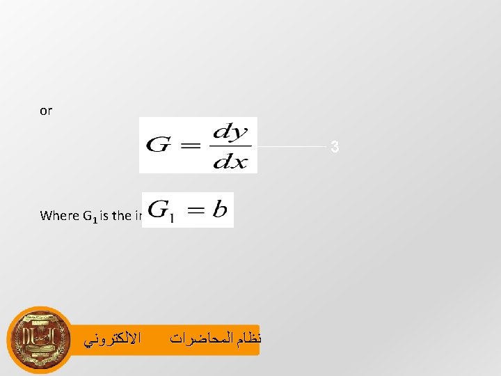
Slope of Curve • To define ‘a’ and ‘b’, first derivative of equation 1 gives the slope. 2 • At PVC, x=0; ﺍﻻﻟﻜﺘﺮﻭﻧﻲ ﻧﻈﺎﻡ ﺍﻟﻤﺤﺎﺿﺮﺍﺕ
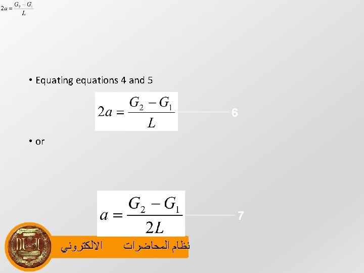
• Taking second derivative of equation 1, i. e. rate of change of slope; • The rate of change of slope can also be written as; 4 ﺍﻻﻟﻜﺘﺮﻭﻧﻲ ﻧﻈﺎﻡ ﺍﻟﻤﺤﺎﺿﺮﺍﺕ 5
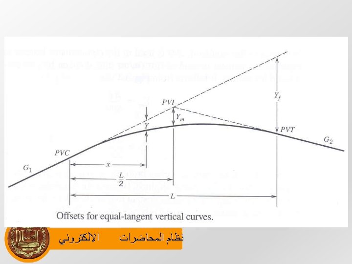
Fundamentals of Vertical Curves • For vertical curve design and construction, offsets which are vertical distances from initial tangent to the curve are important for vertical curve design. ﺍﻻﻟﻜﺘﺮﻭﻧﻲ ﻧﻈﺎﻡ ﺍﻟﻤﺤﺎﺿﺮﺍﺕ
• A vertical curve also simplifies the computation of the high and low points or crest and sag vertical curves respectively, since high or low point does not occur at the curve ends PVC or PVT. • Let ‘Y’ is the offset at any distance ‘x’ from PVC. ﺍﻻﻟﻜﺘﺮﻭﻧﻲ ﻧﻈﺎﻡ ﺍﻟﻤﺤﺎﺿﺮﺍﺕ
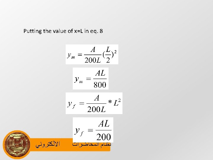
• Ym is the mid curve offset & Yt is the offset at the end of the vertical curve. • From an equal tangent parabola, it can be written as; where ‘y’ is the offset in feet and 8‘A’ is the absolute value of the difference in grades(G 2 G 1, in %), ‘L’ is length of vertical curve in feet and ‘x’ is distance from the PVC in feet. ﺍﻻﻟﻜﺘﺮﻭﻧﻲ ﻧﻈﺎﻡ ﺍﻟﻤﺤﺎﺿﺮﺍﺕ
• First derivative can be used to determine the location of the low point, the alternative to this is to use a k-value which is defined as where ‘L’ is in feet and ‘A’ is in %. ﺍﻻﻟﻜﺘﺮﻭﻧﻲ ﻧﻈﺎﻡ ﺍﻟﻤﺤﺎﺿﺮﺍﺕ
• This value ‘k’ can be used directly to compute the high / low points for crest/ sag vertical curves by x=k. G 1 where ‘x’ is the distance from the PVC to the high/ low point. ‘k’ can also be defined as the horizontal distance in feet required to affect a 1% change in the slope. ﺍﻻﻟﻜﺘﺮﻭﻧﻲ ﻧﻈﺎﻡ ﺍﻟﻤﺤﺎﺿﺮﺍﺕ
A 500 -meter equal-tangent sag vertical curve has the PVC at station 100+00 with an elevation of 1000 m. The initial grade is -4% and the final grade is +2%. Determine the stationing and elevation of the PVI, the PVT, and the lowest point on • the Solution : The curve length is stated to be 500 meters. Therefore, the PVT is at station 105+00 (100+00 + 5+00) and the PVI is in the very middle at 102+50, since it is an equal tangent curve. For the parabolic formulation, equals the elevation at the PVC, which is stated as 1000 m. The value of b equals the initial grade, which in decimal is -0. 04. The value of a can then be found as 0. 00006. • Basic Equation of the parabola: y = ax 2+bx+c • At x= 0 y= C=1000 b= G 1= -0. 04 , a = G 2 -G 1/2 L =(0. 02 -0. 04))/2 x 500=0. 00006 • Using the general parabolic formula, the elevation of the PVT can be found: • y = 0. 00006 x 2+ (-0. 04 x)+c = 0. 00006(500)+(-0. 04*500)+1000= 995 m Since the PVI is the intersect of the two tangents, the slope of either tangent and the elevation of the PVC or PVT, depending, can be used as reference. The elevation of the PVI can then be found as : y = -0. 04(250)+1000= 990 m To find the lowest part of the curve, the first derivative of the parabolic formula can be found. The lowest point has a slope of zero, and thus the low point location can be found: dy/dx = 0. 00012 x-0. 04 = 0 x = 0. 04/0. 00012= 333 m Using the parabolic formula, the elevation can be computed for that location. It turns out to be at an elevation of 993. 33 m, which is the lowest point along the curve. ﺍﻻﻟﻜﺘﺮﻭﻧﻲ ﻧﻈﺎﻡ ﺍﻟﻤﺤﺎﺿﺮﺍﺕ
Sight Distances • Sight Distance is a length of road surface which a particular driver can see with an acceptable level of clarity. Sight distance plays an important role in geometric highway design because it establishes an acceptable design speed, based on a driver's ability to visually identify and stop for a particular, unforeseen roadway hazard or pass a slower vehicle without being in conflict with opposing traffic. • As velocities on a roadway are increased, the design must be catered to allowing additional viewing distances to allow for adequate time to stop. The two types of sight distance are: • (1) stopping sight distance and (2) passing sight distance. ﺍﻻﻟﻜﺘﺮﻭﻧﻲ ﻧﻈﺎﻡ ﺍﻟﻤﺤﺎﺿﺮﺍﺕ
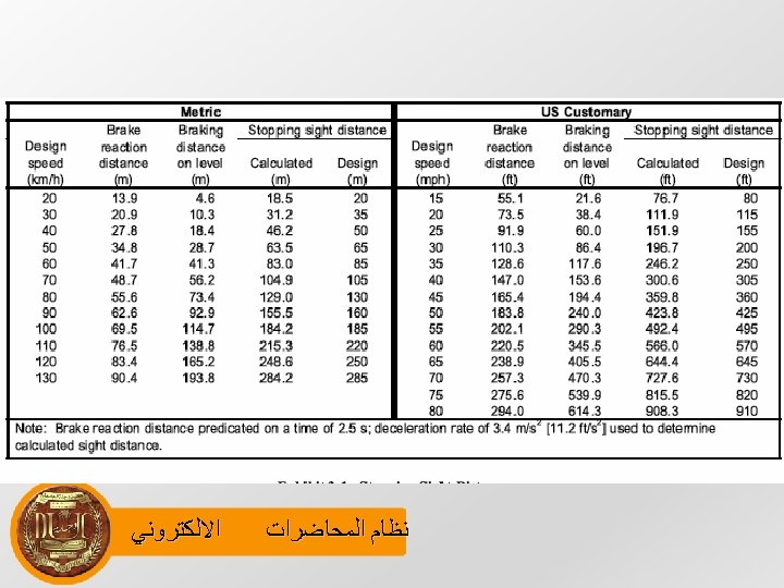
Stopping Sight Distance At every point on the roadway, the minimum sight distance provided should be sufficient to enable a vehicle traveling at the design speed to stop before reaching a stationary object in its path. Stopping sight distance is the aggregate of two distances: • brake reaction distance and braking distance. • Brake reaction time is the interval between the instant that the driver recognizes the existence of an object or hazard ahead and the instant that the brakes are actually applied. Extensive studies have been conducted to ascertain brake reaction time. Minimum reaction times can be as little as 1. 64 seconds: 0. 64 for alerted drivers plus 1 second for the unexpected signal. • Some drivers may take over 3. 5 seconds to respond under similar circumstances. For approximately 90% of drivers, including older ﺍﻻﻟﻜﺘﺮﻭﻧﻲ ﻧﻈﺎﻡ ﺍﻟﻤﺤﺎﺿﺮﺍﺕ drivers, a reaction time of 2. 5 see is considered adequate. This value is therefore used in Table on next page
Vehicle Stopping Distance • Vehicle stopping distance is calculated by the following formula where V 1 f G ﺍﻻﻟﻜﺘﺮﻭﻧﻲ initial speed of vehicle friction percent grade ﻧﻈﺎﻡ ﺍﻟﻤﺤﺎﺿﺮﺍﺕ
Distance Traveled During Perception/ Reaction Time • It is calculated by the following formula dr = V 1 * t r where V 1 Initial Velocity of vehicle tr time required to perceive and react to the need to stop ﺍﻻﻟﻜﺘﺮﻭﻧﻲ ﻧﻈﺎﻡ ﺍﻟﻤﺤﺎﺿﺮﺍﺕ
• Hence formula for the Stopping sight distance will be; ﺍﻻﻟﻜﺘﺮﻭﻧﻲ ﻧﻈﺎﻡ ﺍﻟﻤﺤﺎﺿﺮﺍﺕ
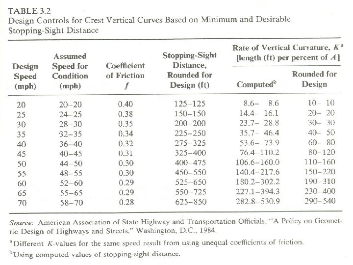
SSD and Crest Vertical Curve • In providing the sufficient SSD on a vertical curve, the length of curve ‘L’ is the critical concern. • Longer lengths of curve provide more SSD, all else being equal, but are most costly to construct. • Shorter curve lengths are relatively inexpensive to construct but may not provide adequate SSD. • In developing such an expression, crest and sag vertical curves are considered separately. • For the crest vertical curve case, consider the diagram. ﺍﻻﻟﻜﺘﺮﻭﻧﻲ ﻧﻈﺎﻡ ﺍﻟﻤﺤﺎﺿﺮﺍﺕ
SSD and Crest Vertical Curve S H 1 PVI PVT PVC H 2 L S = Sight distance (ft) H 1= height of driver’s eye above road-way surface (ft) L = length of the curve (ft), H 2= height of roadway object (ft) , ﻧﻈﺎﻡ ﺍﻟﻤﺤﺎﺿﺮﺍﺕ A = ﺍﻻﻟﻜﺘﺮﻭﻧﻲ difference in grade Lm= Minimum length required for sight distance.
Minimum Length of the Curve • For a required sight distance S is calculated as follows; • If the sight distance is found to be less than the curve length (S>L) • for sight distances that are greater than the curve length (S<L) ﺍﻻﻟﻜﺘﺮﻭﻧﻲ ﻧﻈﺎﻡ ﺍﻟﻤﺤﺎﺿﺮﺍﺕ
• For the sight distance required to provide adequate SSD, standard define driver eye height H 1 is 3. 5 ft and object height H 2 is 0. 5 ft. S is assumed is equal to SSD. We get SSD > L SSD < L ﺍﻻﻟﻜﺘﺮﻭﻧﻲ ﻧﻈﺎﻡ ﺍﻟﻤﺤﺎﺿﺮﺍﺕ
• Working with the above equations can be cumbersome. • To simplify matters on crest curves computations, K- values, are used. L = K*A where k is the horizontal distance in feet, required to affect 1 percent change in slope. ﺍﻻﻟﻜﺘﺮﻭﻧﻲ ﻧﻈﺎﻡ ﺍﻟﻤﺤﺎﺿﺮﺍﺕ
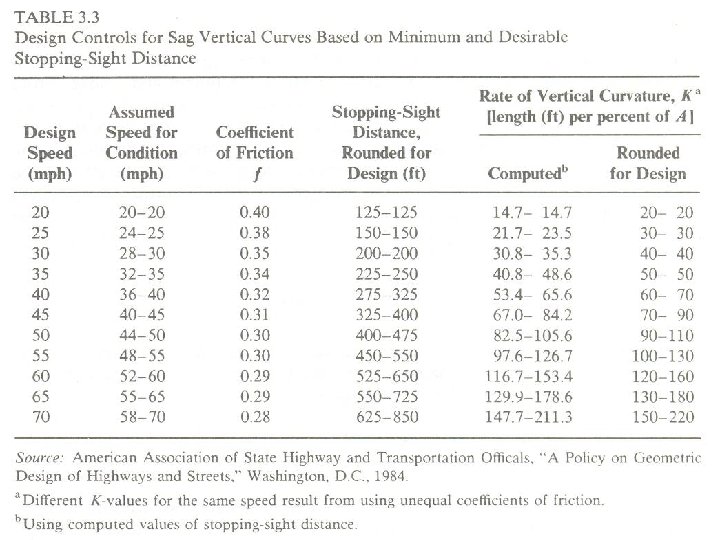
SSD and Sag Vertical Curve • Sag vertical curve design differs from crest vertical curve design in the sense that sight distance is governed by night time conditions, because in daylight, sight distance on a sag vertical curve is unrestricted. • The critical concern for sag vertical curve is the headlight sight distance which is a function of the height of the head light above the road way, H, and the inclined upward angle of the head light beam, relative to the horizontal plane of the car, β. ﺍﻻﻟﻜﺘﺮﻭﻧﻲ ﻧﻈﺎﻡ ﺍﻟﻤﺤﺎﺿﺮﺍﺕ
• The sag vertical curve sight distance problem is illustrated in the following figure. S H ﺍﻻﻟﻜﺘﺮﻭﻧﻲ PV C ﻧﻈﺎﻡ ﺍﻟﻤﺤﺎﺿﺮﺍﺕ β P L VI PV T
• By using the properties of parabola for an equal tangent curve, it can be shown that minimum length of the curve, Lm for a required sight distance is ; • For S>L • For S<L ﺍﻻﻟﻜﺘﺮﻭﻧﻲ ﻧﻈﺎﻡ ﺍﻟﻤﺤﺎﺿﺮﺍﺕ
• For the sight distance required to provide adequate SSD, use a head light height of 2. 0 ft and an upward angle of 1 degree. • Substituting these design standards and S = SSD in the above equations; • For SSD>L • For SSD<L ﺍﻻﻟﻜﺘﺮﻭﻧﻲ ﻧﻈﺎﻡ ﺍﻟﻤﺤﺎﺿﺮﺍﺕ
• As was the case for crest vertical curves, K-values can also be computed for sag vertical curves. • Caution should be exercised in using the k-values in this table since the assumption of G=0 percent is used for SSD computations. ﺍﻻﻟﻜﺘﺮﻭﻧﻲ ﻧﻈﺎﻡ ﺍﻟﻤﺤﺎﺿﺮﺍﺕ
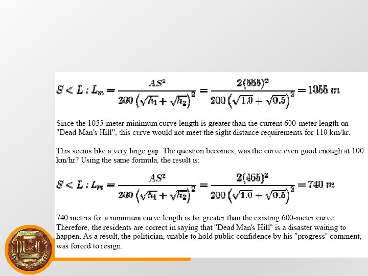
Engineering vs. Politics • A current roadway has a design speed of 100 km/hr, a coefficient of friction of 0. 1, and carries drivers with perception-reaction times of 2. 5 seconds. The drivers use cars that allows their eyes to be 1 meter above the road. Because of ample road kill in the area, the road has been designed for cases that are 0. 5 meters in height. All curves along that road have been designed accordingly. • The local government, seeing the potential of tourism in the area and the boost to the local economy, wants to increase the speed limit to 110 km/hr to attract summer drivers. Residents along the route claim that this is a horrible idea, as a particular curve called "Dead Man's Hill" would earn its name because of sight distance problems. "Dead Man's Hill" is a crest curve that is roughly 600 meters in length. It starts with a grade of +1. 0% and ends with (-1. 0)%. There has never been an accident on "Dead Man's Hill" as of yet, but residents truly believe one will come about in the near future. ﺍﻻﻟﻜﺘﺮﻭﻧﻲ ﻧﻈﺎﻡ ﺍﻟﻤﺤﺎﺿﺮﺍﺕ
• A local politician who knows little to nothing about engineering (but thinks he does) states that the 600 -meter length is a long distance and more than sufficient to handle the transition of eager big-city drivers. Still, the residents push back, saying that 600 meters is not nearly the distance required for the speed. The politician begins a lengthy campaign to "Bring Tourism to Town", saying that the residents are trying to stop "progress". As an engineer, determine if these residents are indeed making a valid point or if they are simply trying to stop progress? ﺍﻻﻟﻜﺘﺮﻭﻧﻲ ﻧﻈﺎﻡ ﺍﻟﻤﺤﺎﺿﺮﺍﺕ
• Using sight distance formulas from other sections, it is found that 100 km/hr has an SSD of 465 meters and 110 km/hr has an SSD of 555 meters, • Given the criteria stated above. Since both 465 meters and 555 meters are less than the 600 -meter curve length, the correct formula to use would be: ﺍﻻﻟﻜﺘﺮﻭﻧﻲ ﻧﻈﺎﻡ ﺍﻟﻤﺤﺎﺿﺮﺍﺕ
• For flash animation please visit the following site” • http: //street. umn. edu/flash_curve_crest. html ﺍﻻﻟﻜﺘﺮﻭﻧﻲ ﻧﻈﺎﻡ ﺍﻟﻤﺤﺎﺿﺮﺍﺕ
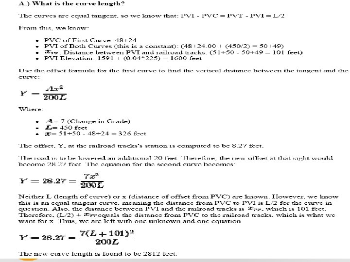
Problem for Pondering • Problem: • To help prevent future collisions between cars and trains, an at-grade crossing of a rail road by a country road is being redesigned so that the county road will pass underneath the tracks. Currently the vertical alignment of the county road consists of an equal tangents crest vertical curve joining a 4% upgrade to a 3% downgrade. The existing vertical curve is 450 feet long, the PVC of this curve is at station 48+24. 00, and the elevation of the PVC is 1591. 00 feet. The centerline of the train tracks is at station 51+50. 00. Your job is to find the shortest vertical curve that provides 20 feet of clearance between the new county road and the train tracks, and to make a preliminary estimate of the cut at the PVI that will be needed to construct the new curve. ﺍﻻﻟﻜﺘﺮﻭﻧﻲ ﻧﻈﺎﻡ ﺍﻟﻤﺤﺎﺿﺮﺍﺕ
• Study the solution and resolve the question by making the sketches etc ﺍﻻﻟﻜﺘﺮﻭﻧﻲ ﻧﻈﺎﻡ ﺍﻟﻤﺤﺎﺿﺮﺍﺕ