
HIGH VOLTAGE ENGINEERING FOR B E EEE STUDENTS
HIGH VOLTAGE ENGINEERING FOR B. E. (EEE) STUDENTS OF ANNA UNIVERSITY Dr M A Panneerselvam, Professor, Anna University 1
INTRODUCTION OF THE FACULTY NAME : Dr. M. A. PANNEERSELVAM QUALIFICATION : B. E. , (ELECTRICAL) M. E (HIGH VOLTAGE ENGINEERING) Ph. D (HIGH VOLTAGE ENGINEERING) AREA OF SPECIALISATION : ELECTRICAL MACHINES & HIGH VOLTAGE Dr M A Panneerselvam, Professor, ENGINEERING Anna University 2
NO. OF PAPERS PUBLISHED : ABOUT 30 IN BOTH NATIONAL & INTERNATIONAL JOURNALS NO. OF Ph. D’s PRODUCED : 4 CANDIDATES WORKING FOR Ph. D. CURRENTLY : 4 Dr M A Panneerselvam, Professor, Anna University 3
LIST OF REFERENCES § 1. High Voltage Engineering -4 th Edition- M. S. Naidu and V. Kamaraju. Tata Mc. Graw-Hill Publishing Co. Ltd. , - New Delhi- 2009. § 2. High Voltage Engineering -3 rd Edition- C. L. Wadhwa - New Age International(P) Ltd. Publishers New Delhi, Bangalore …- 2010. Dr M A Panneerselvam, Professor, Anna University 4
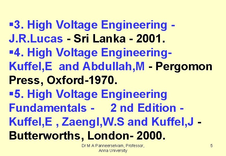
§ 3. High Voltage Engineering J. R. Lucas - Sri Lanka - 2001. § 4. High Voltage Engineering. Kuffel, E and Abdullah, M - Pergomon Press, Oxford-1970. § 5. High Voltage Engineering Fundamentals - 2 nd Edition Kuffel, E , Zaengl, W. S and Kuffel, J Butterworths, London- 2000. Dr M A Panneerselvam, Professor, Anna University 5
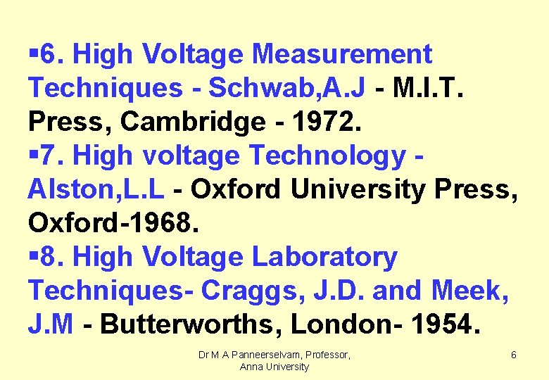
§ 6. High Voltage Measurement Techniques - Schwab, A. J - M. I. T. Press, Cambridge - 1972. § 7. High voltage Technology Alston, L. L - Oxford University Press, Oxford-1968. § 8. High Voltage Laboratory Techniques- Craggs, J. D. and Meek, J. M - Butterworths, London- 1954. Dr M A Panneerselvam, Professor, Anna University 6
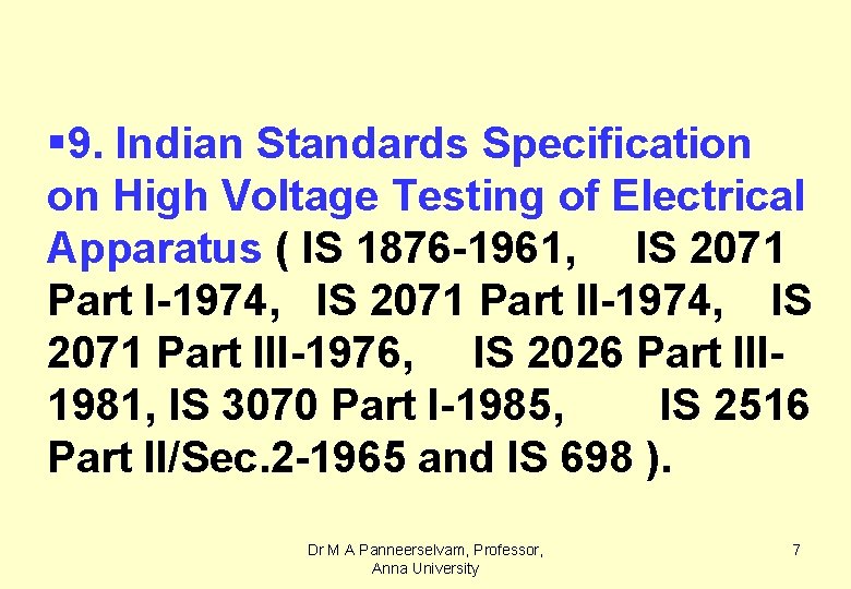
§ 9. Indian Standards Specification on High Voltage Testing of Electrical Apparatus ( IS 1876 -1961, IS 2071 Part I-1974, IS 2071 Part III-1976, IS 2026 Part III 1981, IS 3070 Part I-1985, IS 2516 Part II/Sec. 2 -1965 and IS 698 ). Dr M A Panneerselvam, Professor, Anna University 7
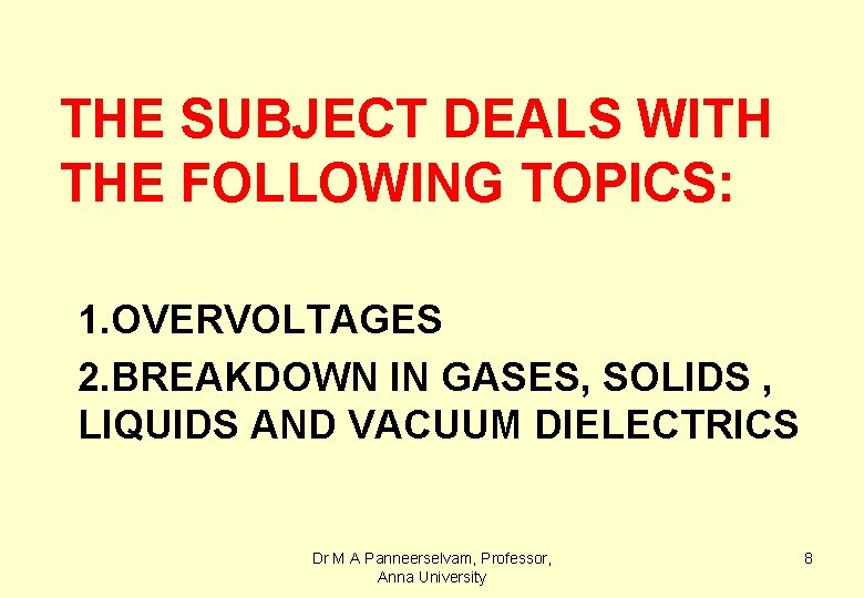
THE SUBJECT DEALS WITH THE FOLLOWING TOPICS: 1. OVERVOLTAGES 2. BREAKDOWN IN GASES, SOLIDS , LIQUIDS AND VACUUM DIELECTRICS Dr M A Panneerselvam, Professor, Anna University 8
3. GENERATION OF VERY HIGH VOLTAGES AND CURRENTS 4. MEASUREMENT OF VERY HIGH VOLTAGES AND CURRENTS 5. HIGH VOLTAGE TESTING & INSULATION COORDINATION Dr M A Panneerselvam, Professor, Anna University 9
UNIT 1 : OVERVOLTAGES 1. 0 NATURE OF OVERVOLTAGES § 1. External overvoltages / Lightning overvoltages Dr M A Panneerselvam, Professor, Anna University 10
§ 2. Internal overvoltages / Switching surges § 3. Power frequency overvoltages due to system faults § 4. DC overvoltages Dr M A Panneerselvam, Professor, Anna University 11
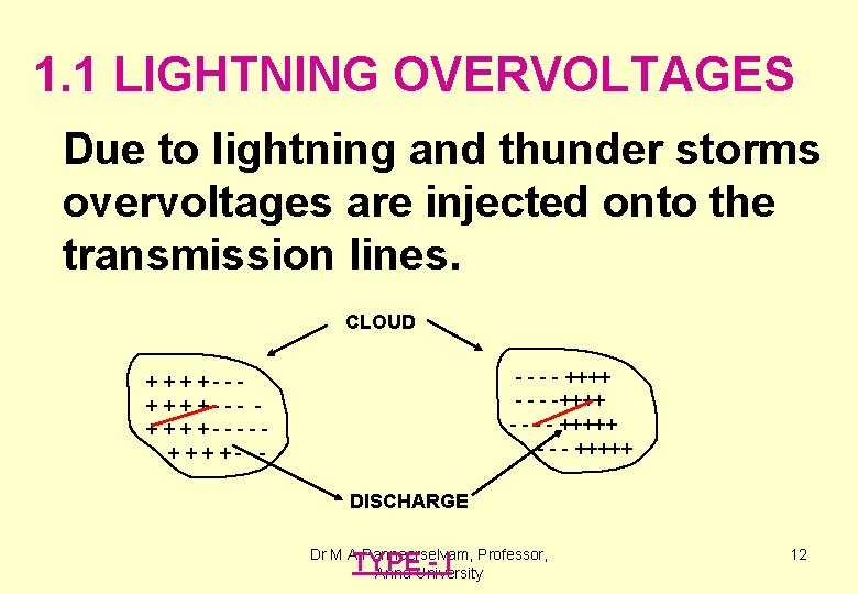
1. 1 LIGHTNING OVERVOLTAGES Due to lightning and thunder storms overvoltages are injected onto the transmission lines. CLOUD - - ++++ - - - - +++++ ++++----++++--DISCHARGE Dr M A Panneerselvam, Professor, Anna University TYPE - I 12
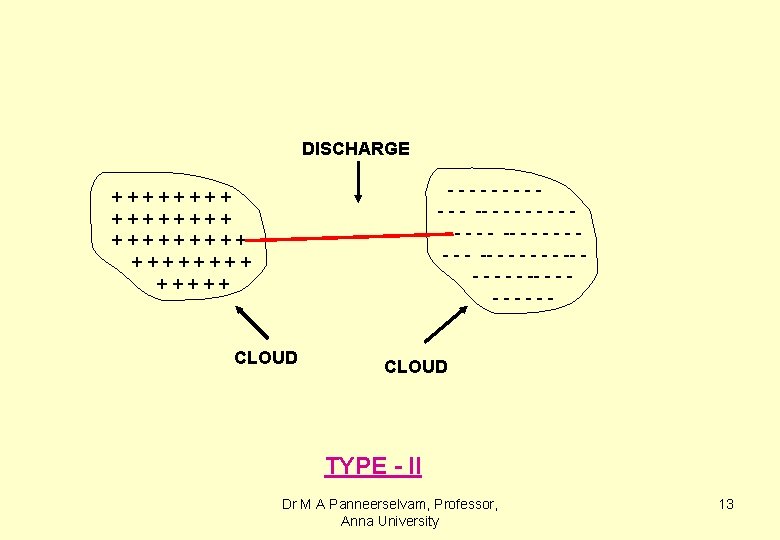
DISCHARGE ----- - - - - -- - - - - - ------ ++++++++ +++++ CLOUD TYPE - II Dr M A Panneerselvam, Professor, Anna University 13
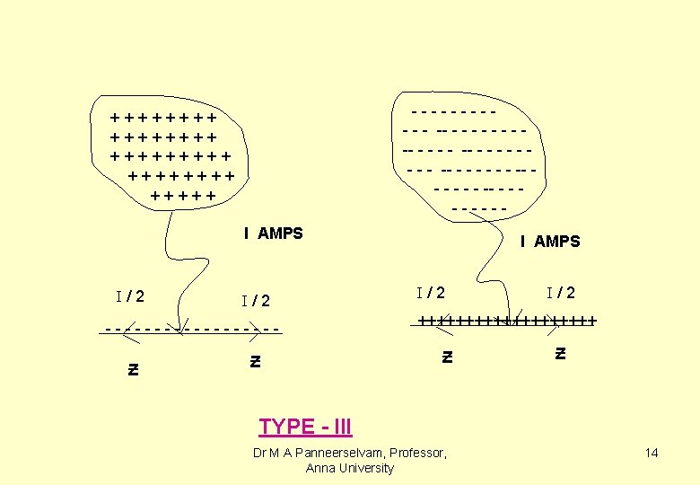
----- - - - - -- - - - - - ------ ++++++++ +++++ I AMPS /2 ---------Ƶ Ƶ I AMPS /2 ++++++++++ Ƶ Ƶ TYPE - III Dr M A Panneerselvam, Professor, Anna University 14
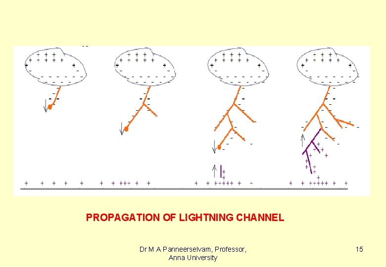
PROPAGATION OF LIGHTNING CHANNEL Dr M A Panneerselvam, Professor, Anna University 15
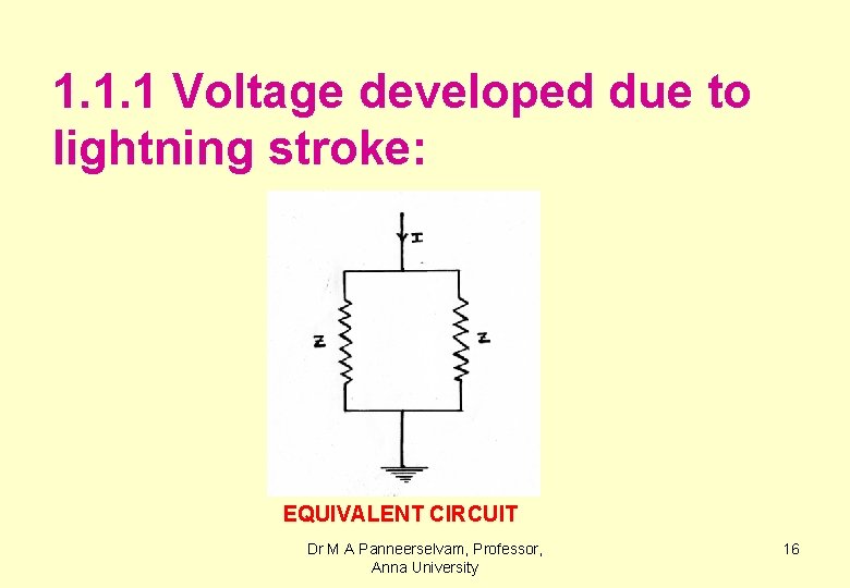
1. 1. 1 Voltage developed due to lightning stroke: EQUIVALENT CIRCUIT Dr M A Panneerselvam, Professor, Anna University 16
For a lightning stroke current of 200 k. A and assuming a surge impedance of 400 Ω for overhead line, the voltage developed is equal to( I x Z/ 2 ) = 200 x 103 x 400/2 = 40 x 106 = 40 MV. 1. 1. 2 Traveling waves on transmission lines : Dr M A Panneerselvam, Professor, Anna University 17
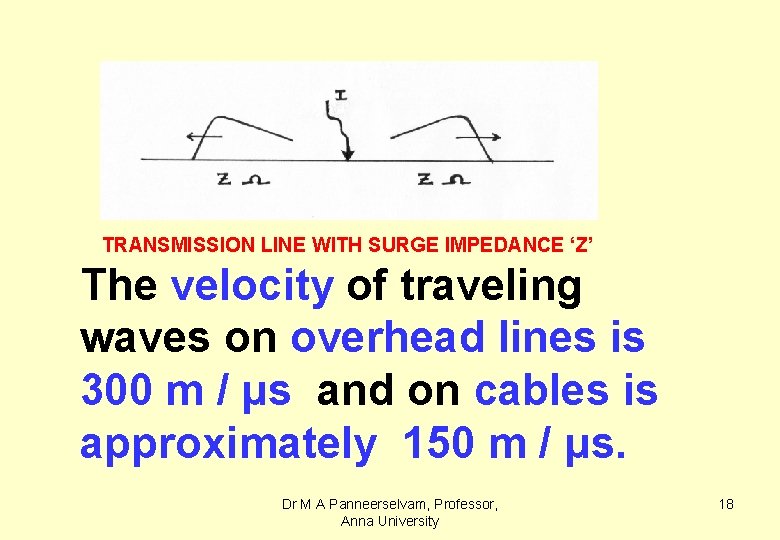
TRANSMISSION LINE WITH SURGE IMPEDANCE ‘Z’ The velocity of traveling waves on overhead lines is 300 m / μs and on cables is approximately 150 m / μs. Dr M A Panneerselvam, Professor, Anna University 18
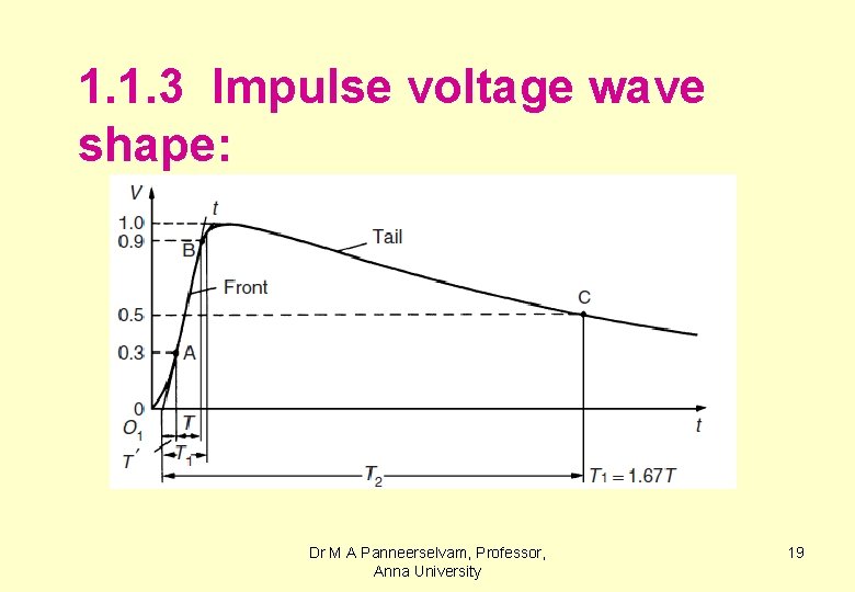
1. 1. 3 Impulse voltage wave shape: Dr M A Panneerselvam, Professor, Anna University 19
Specification for impulse voltage: ( AS PER INDIAN STANDARDS ) t 1 Time to Front 1. 2 s t 2 Time to Tail 50 s Vp Peak voltage Dr M A Panneerselvam, Professor, Anna University 20
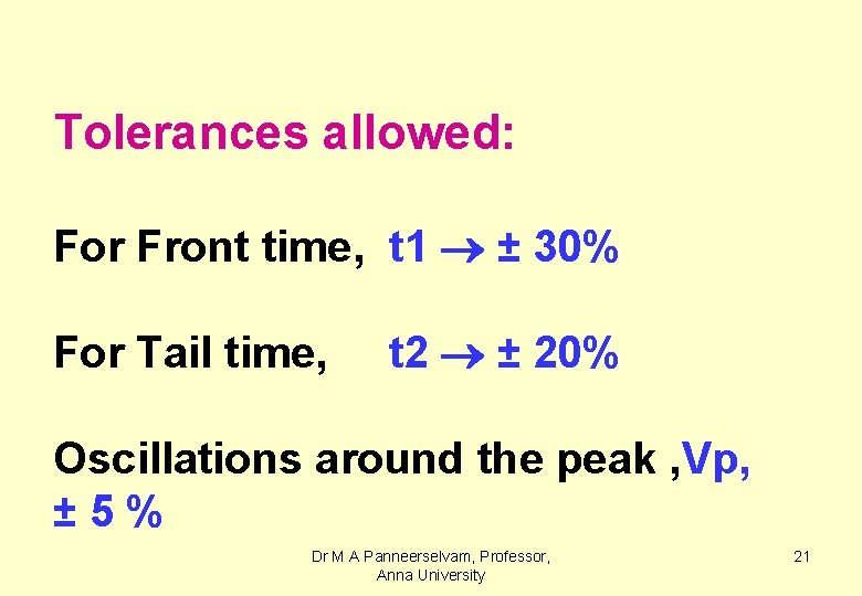
Tolerances allowed: For Front time, t 1 ± 30% For Tail time, t 2 ± 20% Oscillations around the peak , Vp, ± 5% Dr M A Panneerselvam, Professor, Anna University 21
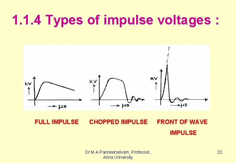
1. 1. 4 Types of impulse voltages : FULL IMPULSE CHOPPED IMPULSE FRONT OF WAVE IMPULSE Dr M A Panneerselvam, Professor, Anna University 22
1. 2 INTERNAL OVERVOLTAGES (SWITCHING SURGES) 1. 2. 1 Reasons for switching surge voltages: • Sudden opening of a line • Sudden closing of a line Dr M A Panneerselvam, Professor, Anna University 23
• Connection of inductance / Capacitance • Sudden connection and removal of loads , etc. Any sudden disturbance taking place in a transmission line will cause switching surge. Dr M A Panneerselvam, Professor, Anna University 24
For the range of values of the inductance and capacitance of overhead lines the frequency of the switching surges are generally in the range of kc/s and they exist for a duration of milliseconds. Dr M A Panneerselvam, Professor, Anna University 25
1. 2. 2 Switching surges on transmission lines: Ex. 1 Opening of an unloaded OH line: Simply opening of an unloaded line transmission line may result in switching surge as shown in the fig. Dr M A Panneerselvam, Professor, Anna University 26
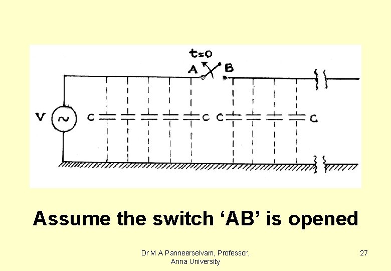
Assume the switch ‘AB’ is opened Dr M A Panneerselvam, Professor, Anna University 27
at time, t = 0, when the AC voltage is at its peak. During the next half cycle the voltage at terminal ‘A’ changes to negative peak of AC voltage , wheras the voltage at terminal ‘B’ remains at positive peak. Hence the voltage across the Dr M A Panneerselvam, Professor, Anna University 28
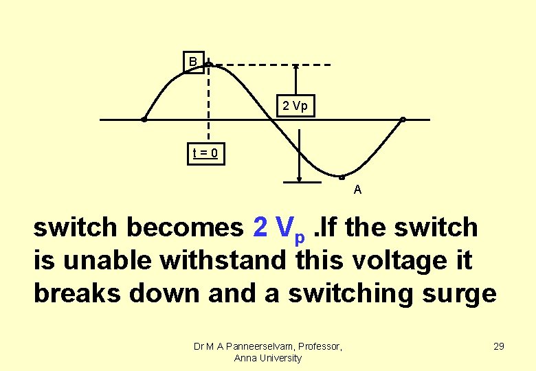
B 2 Vp t=0 A switch becomes 2 Vp. If the switch is unable withstand this voltage it breaks down and a switching surge Dr M A Panneerselvam, Professor, Anna University 29
of magnitude 2 Vp travels on the line. At the terminations it gets reflected and refracted and builds up further to a higher level. Another example for generation of switching surge is the operation of a circuit breaker as shown in the next figure. Dr M A Panneerselvam, Professor, Anna University 30
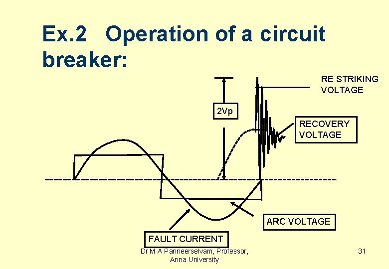
Ex. 2 Operation of a circuit breaker: RE STRIKING VOLTAGE 2 Vp RECOVERY VOLTAGE ARC VOLTAGE FAULT CURRENT Dr M A Panneerselvam, Professor, Anna University 31
RESTRIKING VOLTAGE ACROSS A CIRCUIT BREAKER The maximum voltage across the breaker contacts = 2 Vp =2√ 2 VRMS The voltage after reflection and refraction at the terminals of the transmission line may reach a maximum of 5 t 0 6 times the system voltage. Dr M A Panneerselvam, Professor, Anna University 32
1. 3 PF OVERVOLTAGES DUE TO LOCAL SYSTEM FAULTS 1. 3. 1 Local faults in the systems are : Line to ground fault (3) § Double line to ground fault (3) § Dr M A Panneerselvam, Professor, Anna University 33
§ Double line fault (3) § Triple line fault (1) § Triple line to ground fault (1) Of the total 11 faults above, a double line to ground fault is more dangerous with respect to Dr M A Panneerselvam, Professor, Anna University 34
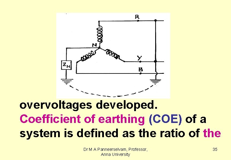
overvoltages developed. Coefficient of earthing (COE) of a system is defined as the ratio of the Dr M A Panneerselvam, Professor, Anna University 35
voltage of the healthy phase to ground to that of the line voltage in the event of a double line to ground fault. The value of COE varies between 1/√ 3 to 1. 0(i. e. , 0. 59 to 1. 0) depending upon the neutral impedance. Dr M A Panneerselvam, Professor, Anna University 36
When the value of ‘COE” is less than 70 % , the system is said to be an effectively or solidly earthed system. When the ‘COE’ is more than 70 %, the system is said to be a non effectively earthed system. Dr M A Panneerselvam, Professor, Anna University 37
Systems above 230 k. V are generally effectively earthed. For System ratings above 230 k. V the Switching surge voltages attain very high values and become more severe than impulse voltages. Dr M A Panneerselvam, Professor, Anna University 38
Hence, the insulation design (i. e. , insulation coordination) is based on switching surges rather than impulse voltages. 1. 4 DC OVERVOLTAGES q. During the past 2 to 3 decades HVDC systems came into existence. Dr M A Panneerselvam, Professor, Anna University 39
q. HVDC systems have converters and inverters at the sending end and receiving end respectively employing thyristers. q. Switching surges are produced due to thyristers’ operation. Dr M A Panneerselvam, Professor, Anna University 40
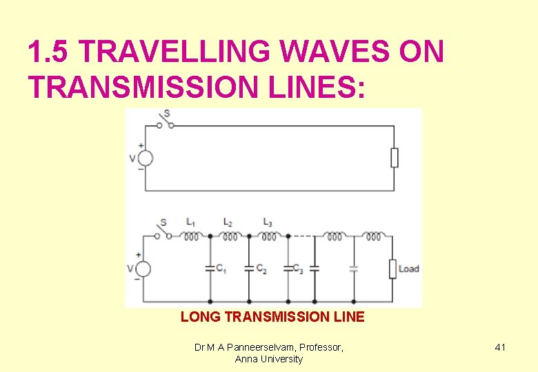
1. 5 TRAVELLING WAVES ON TRANSMISSION LINES: LONG TRANSMISSION LINE Dr M A Panneerselvam, Professor, Anna University 41
Assuming a lossless line (i. e. , R=0, G=0) when the wave has travelled a distance ‘x’ after a time ‘t’, the electrostatic flux associated with the voltage wave is, q = Cx. V ------(1) The current is given by the rate of charge flow , I = dq/dt = VC dx/dt---(2) Dr M A Panneerselvam, Professor, Anna University 42
Here dx/dt is the velocity of the travelling wave represented by, I = VC v ----------(3) Similarly, the electromagnetic flux associated with the current wave, Φ = Lx I -----------(4) Dr M A Panneerselvam, Professor, Anna University 43
The voltage is the rate of change of flux linkages, V = LI dx/dt = LIv ----------(5) Dividing Eqn. (5) by (3), V/I= LIv/VCv = LI/CV V 2/I 2=L/C. i. e. , V/I=Z=√(L/C) ----(6) Next multiplying Eqn. (5) and (6), Dr M A Panneerselvam, Professor, Anna University 44
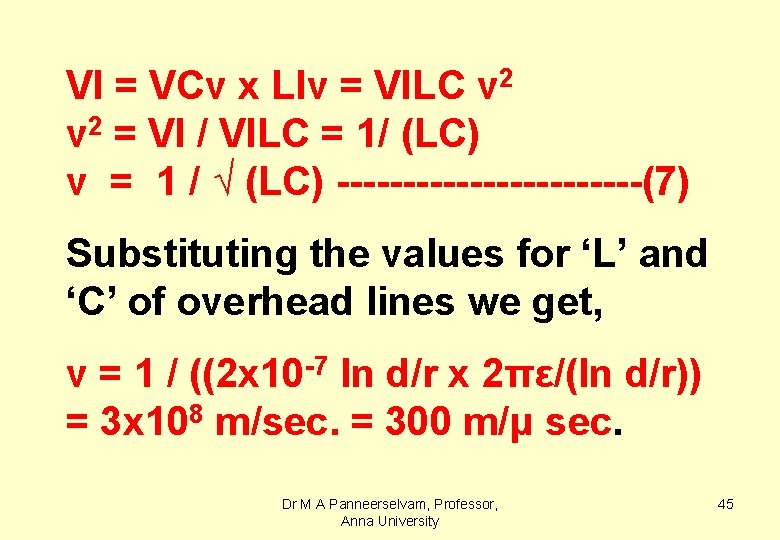
VI = VCv x LIv = VILC v 2 = VI / VILC = 1/ (LC) v = 1 / √ (LC) ------------(7) Substituting the values for ‘L’ and ‘C’ of overhead lines we get, v = 1 / ((2 x 10 -7 ln d/r x 2πε/(ln d/r)) = 3 x 10⁸ m/sec. = 300 m/μ sec. Dr M A Panneerselvam, Professor, Anna University 45
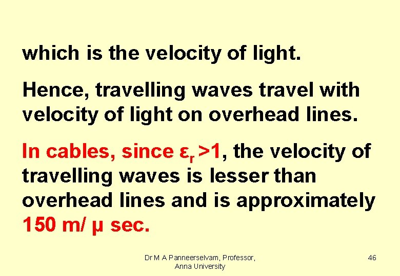
which is the velocity of light. Hence, travelling waves travel with velocity of light on overhead lines. In cables, since εr >1, the velocity of travelling waves is lesser than overhead lines and is approximately 150 m/ μ sec. Dr M A Panneerselvam, Professor, Anna University 46
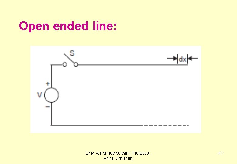
Open ended line: Dr M A Panneerselvam, Professor, Anna University 47
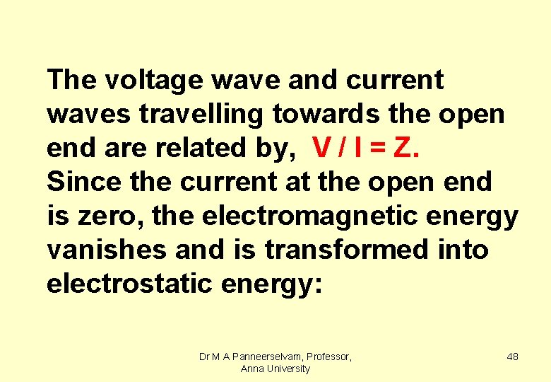
The voltage wave and current waves travelling towards the open end are related by, V / I = Z. Since the current at the open end is zero, the electromagnetic energy vanishes and is transformed into electrostatic energy: Dr M A Panneerselvam, Professor, Anna University 48
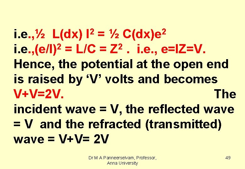
i. e. , ½ L(dx) I 2 = ½ C(dx)e 2 i. e. , (e/I)2 = L/C = Z 2. i. e. , e=IZ=V. Hence, the potential at the open end is raised by ‘V’ volts and becomes V+V=2 V. The incident wave = V, the reflected wave = V and the refracted (transmitted) wave = V+V= 2 V Dr M A Panneerselvam, Professor, Anna University 49
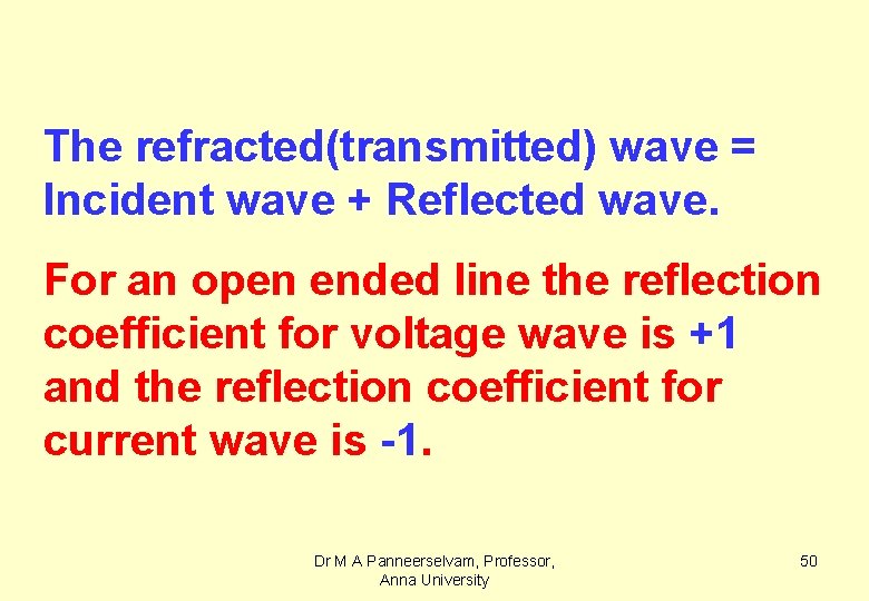
The refracted(transmitted) wave = Incident wave + Reflected wave. For an open ended line the reflection coefficient for voltage wave is +1 and the reflection coefficient for current wave is -1. Dr M A Panneerselvam, Professor, Anna University 50
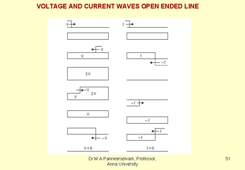
VOLTAGE AND CURRENT WAVES OPEN ENDED LINE Dr M A Panneerselvam, Professor, Anna University 51
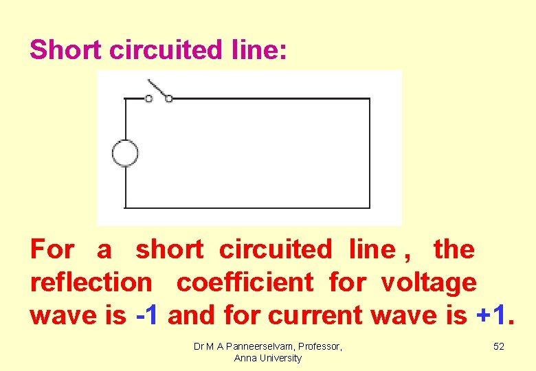
Short circuited line: For a short circuited line , the reflection coefficient for voltage wave is -1 and for current wave is +1. Dr M A Panneerselvam, Professor, Anna University 52
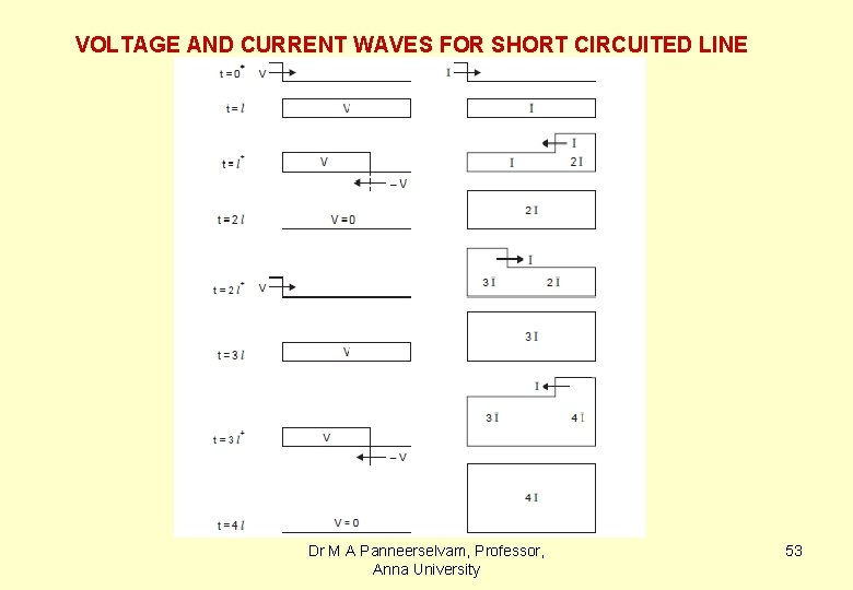
VOLTAGE AND CURRENT WAVES FOR SHORT CIRCUITED LINE Dr M A Panneerselvam, Professor, Anna University 53
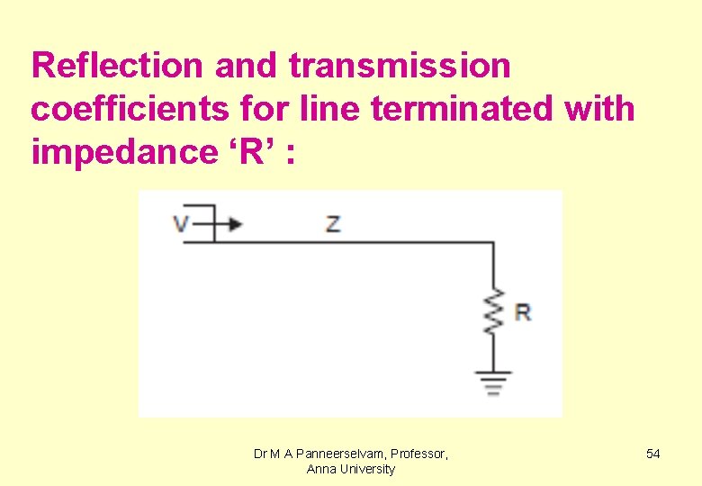
Reflection and transmission coefficients for line terminated with impedance ‘R’ : Dr M A Panneerselvam, Professor, Anna University 54
Let the incident voltage and current waves be V and I, the reflected waves V’ and I’ and the transmitted waves V’’ and I’’. It is seen in the earlier sections that whatever be the value of terminating impedance, whether it is open or short circuited , either the current wave or Dr M A Panneerselvam, Professor, Anna University 55
voltage wave is reflected back with negative sign, i. e. , I’ = - V’/Z I=V/Z , I’=-V’/Z and I’’=V’’/ R. Since I’’=I+I’ and V’’= V+V’, we have, V’’/R = V/Z – V’/Z =V/Z – (V’’-V)/Z = 2 V/Z – V’’/Z. Dr M A Panneerselvam, Professor, Anna University 56
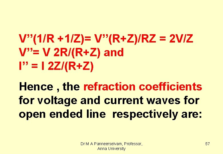
V’’(1/R +1/Z)= V’’(R+Z)/RZ = 2 V/Z V’’= V 2 R/(R+Z) and I’’ = I 2 Z/(R+Z) Hence , the refraction coefficients for voltage and current waves for open ended line respectively are: Dr M A Panneerselvam, Professor, Anna University 57
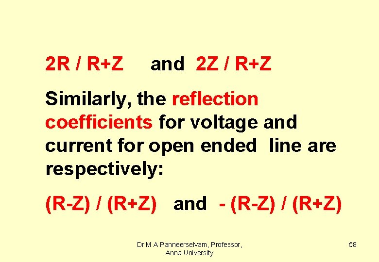
2 R / R+Z and 2 Z / R+Z Similarly, the reflection coefficients for voltage and current for open ended line are respectively: (R-Z) / (R+Z) and - (R-Z) / (R+Z) Dr M A Panneerselvam, Professor, Anna University 58
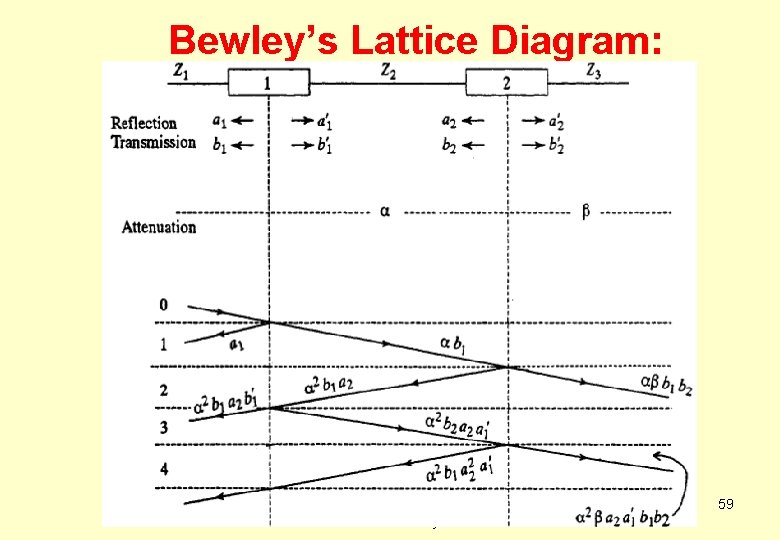
Bewley’s Lattice Diagram: Dr M A Panneerselvam, Professor, Anna University 59
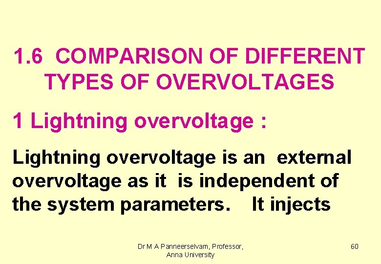
1. 6 COMPARISON OF DIFFERENT TYPES OF OVERVOLTAGES 1 Lightning overvoltage : Lightning overvoltage is an external overvoltage as it is independent of the system parameters. It injects Dr M A Panneerselvam, Professor, Anna University 60
current on to the transmission lines producing a voltage ranging from k. V to MV. It has a wave shape of 1. 2/50 μs and exists for a period of microseconds. The very high rate of rise of the impulse voltage striking the line is Dr M A Panneerselvam, Professor, Anna University 61
equivalent to applying a voltage at very high frequency of the order of Mc/s. 2 Switching Surge : Switching surges are internal overvoltages as they are dependant upon the system Dr M A Panneerselvam, Professor, Anna University 62
parameters (i. e. , the voltage level, the values of R, L and C of the line). Their magnitudes range from 4 to 6 times the system voltage and they have damped oscillations of kc/s and exist for durations of milliseconds. Dr M A Panneerselvam, Professor, Anna University 63
3 Power frequency overvoltage : Due to local system faults such as ‘double line to ground faults’ the voltage of the healthy phase to ground will increase from phase voltage to line voltage depending upon the neural earthing impedance of the system. Dr M A Panneerselvam, Professor, Anna University 64
1. 7 PROTECTION OF TRANSMISSION LINES AGAINST OVERVOLTAGES 1. 5. 0 Transmission lines are protected from lightning and switching surges by adopting the following methods :
1. Use of shielding wires 2. Reduction of tower footing resistance and use of counter poises 3. Using spark gaps ( sphere gap and horn gap ) 4. Connection of surge absorbers Dr M A Panneerselvam, Professor, Anna University 66
5. Overhead lines connected to cables 6. Using protector tubes ( Expulsion Arresters ) 7. Using non-linear resister lightning arresters ( Valve Arresters) Dr M A Panneerselvam, Professor, Anna University 67
1. 7. 1 Shielding wires: § Shielding wires are ground wires connected above phase wires. § The shielding angle should be less than 300 for effective protection of the transmission line against lightning stroke. Dr M A Panneerselvam, Professor, Anna University 68
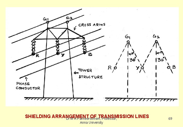
SHIELDING ARRANGEMENT OF TRANSMISSION LINES Dr M A Panneerselvam, Professor, Anna University 69
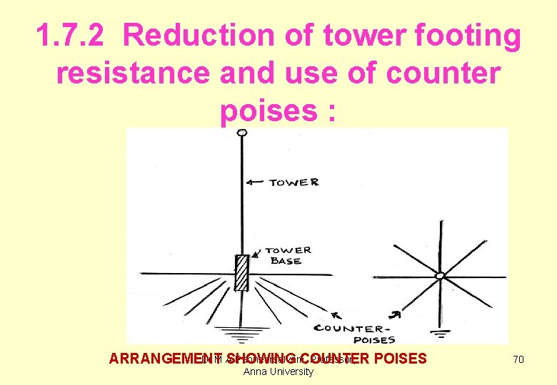
1. 7. 2 Reduction of tower footing resistance and use of counter poises : Dr M A Panneerselvam, Professor, ARRANGEMENT SHOWING COUNTER POISES Anna University 70
1. 7. 3 Spark gaps : When Spark gaps are connected between phase to ground the gaps breakdown due to lightning overvoltage and lightning energy is diverted to ground through gaps. Dr M A Panneerselvam, Professor, Anna University 71
Spark gaps are of the following types: §Rod gaps §Horn gaps §Sphere gaps Dr M A Panneerselvam, Professor, Anna University 72
Sphere gaps are generally preferred as they have , §Consistency in breakdown §Less affected by humidity and other atmospheric conditions. §Lesser impulse ratio Dr M A Panneerselvam, Professor, Anna University 73
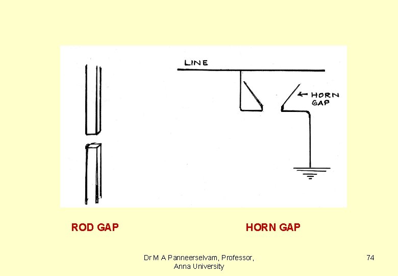
ROD GAP HORN GAP Dr M A Panneerselvam, Professor, Anna University 74
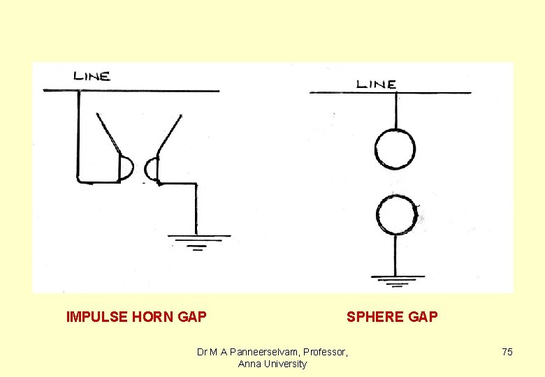
IMPULSE HORN GAP SPHERE GAP Dr M A Panneerselvam, Professor, Anna University 75
IMPULSE RATIO: §Impulse ratio is defined as the ratio of peak impulse breakdown voltage to that of peak power frequency breakdown voltage of a given insulation. Dr M A Panneerselvam, Professor, Anna University 76
Sphere gaps have impulse ratio around unity and hence they offer better protection against lightning overvoltages and helps in reduction of insulation of equipment connected in the system. Dr M A Panneerselvam, Professor, Anna University 77
1. 7. 4 Surge absorbers : • Power loss takes place due to corona at excess overvoltages and helps in the reduction of such overvoltages. • In addition the front time of the impulse voltage is increased resulting in reduced stress on the equipment. Dr M A Panneerselvam, Professor, Anna University 78
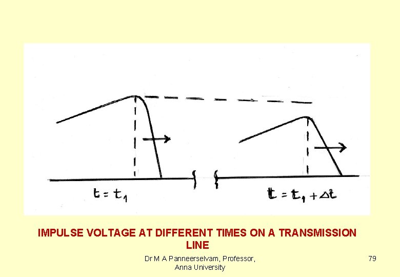
IMPULSE VOLTAGE AT DIFFERENT TIMES ON A TRANSMISSION LINE Dr M A Panneerselvam, Professor, Anna University 79
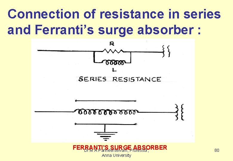
Connection of resistance in series and Ferranti’s surge absorber : FERRANTI’S SURGE ABSORBER Dr M A Panneerselvam, Professor, Anna University 80
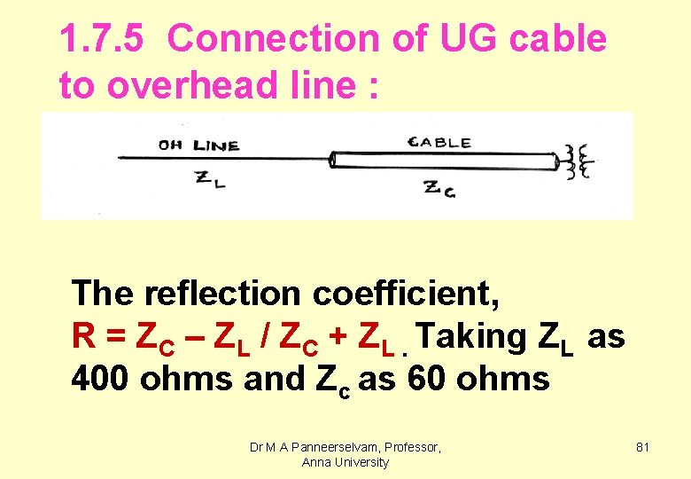
1. 7. 5 Connection of UG cable to overhead line : The reflection coefficient, R = ZC – ZL / ZC + ZL. Taking ZL as 400 ohms and Zc as 60 ohms Dr M A Panneerselvam, Professor, Anna University 81
The reflection coefficient , R = 60 – 400 / 60 + 400 = -340 / 460 = -0. 739 The voltage transmitted into the cable 1. 0 - 0. 739 = 0. 261 pu = 26 % of the incident voltage. Dr M A Panneerselvam, Professor, Anna University 82
1. 7. 6 Protector tubes ( Expulsion Arresters ) : Spark gaps have the following draw backs: § They offer protection against overvoltages by diverting the lightning energy to ground but Dr M A Panneerselvam, Professor, Anna University 83
they cannot arrest the power follow currents. § They are always used as secondary protection except for very small system voltages. Dr M A Panneerselvam, Professor, Anna University 84
The drawbacks of expulsion arrestors are: §They require certain minimum energy to produce gas to quench the arc. §For very high current values they may explode due to very high pressure of gas generated. Dr M A Panneerselvam, Professor, Anna University 85
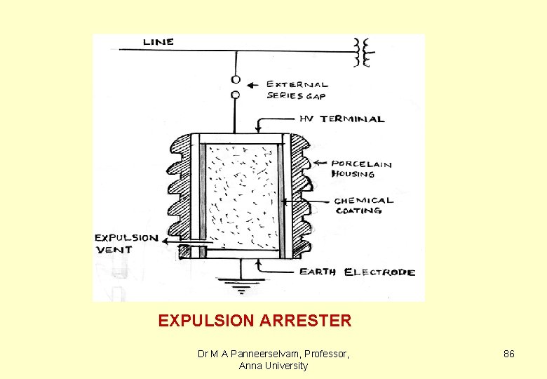
EXPULSION ARRESTER Dr M A Panneerselvam, Professor, Anna University 86
1. 7. 7 Non linear resister lightning arresters( Valve Arresters ) : These arresters act as valve in the sense that they offer very low impedance for lightning voltages and offer very high impedance for power frequency currents. Dr M A Panneerselvam, Professor, Anna University 87
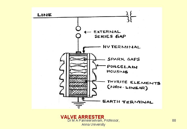
VALVE ARRESTER Dr M A Panneerselvam, Professor, Anna University 88
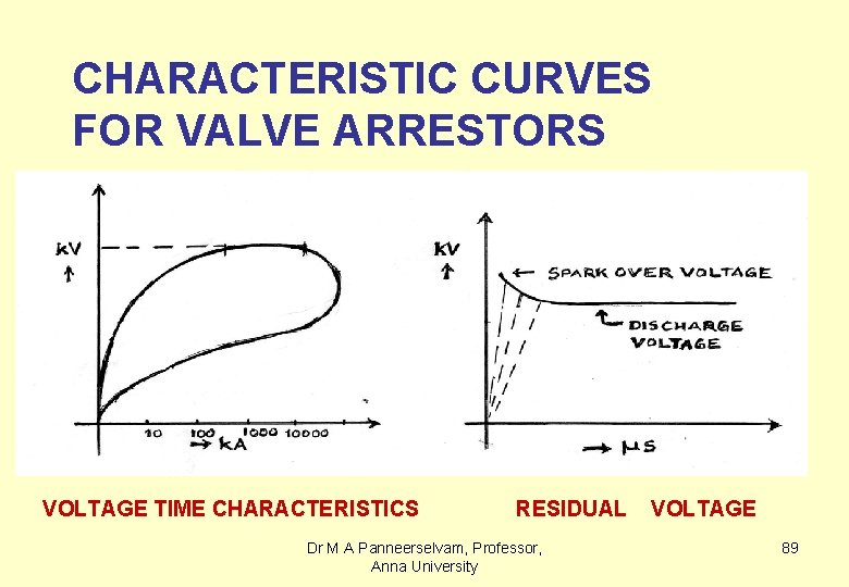
CHARACTERISTIC CURVES FOR VALVE ARRESTORS VOLTAGE TIME CHARACTERISTICS RESIDUAL Dr M A Panneerselvam, Professor, Anna University VOLTAGE 89
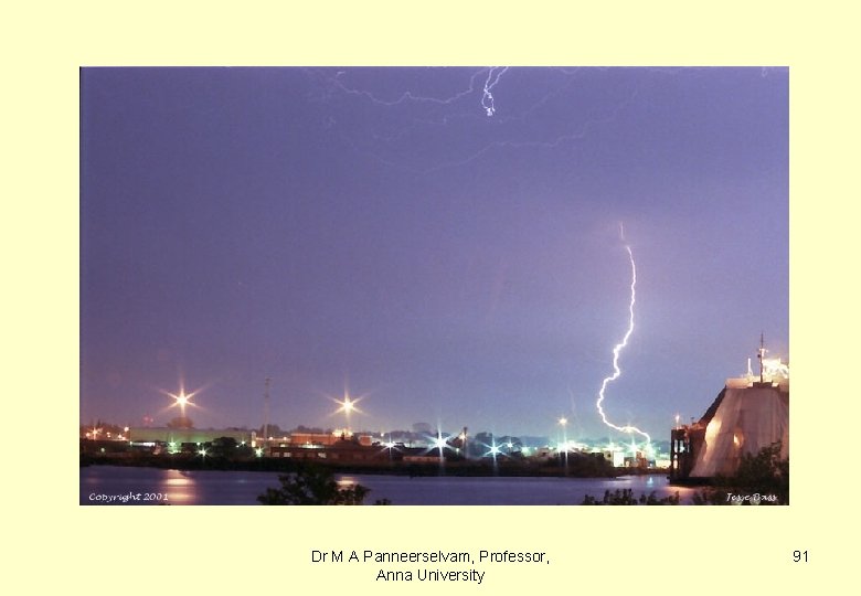
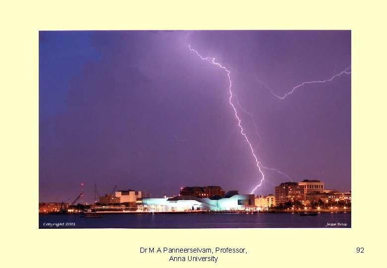
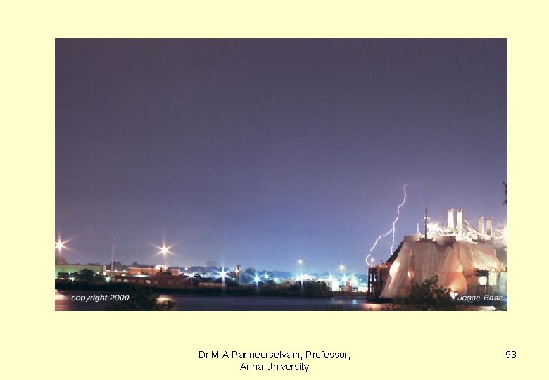
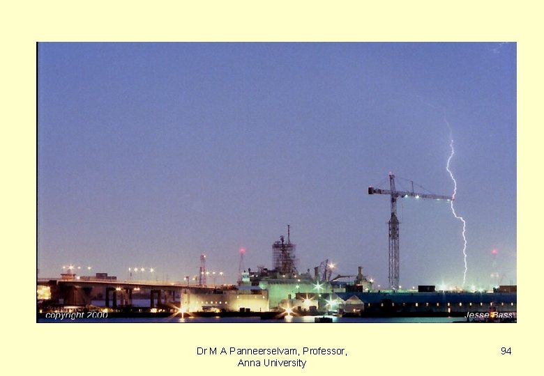
REPRESENTATIVE PHOTOGRAPHS OF LIGHTNING DISCHARGE Dr M A Panneerselvam, Professor, Anna University 90
Dr M A Panneerselvam, Professor, Anna University 91
Dr M A Panneerselvam, Professor, Anna University 92
Dr M A Panneerselvam, Professor, Anna University 93
Dr M A Panneerselvam, Professor, Anna University 94
- Slides: 94