High Power Magnetic Loop Antennas Bill Leonard N

High Power Magnetic Loop Antennas Bill Leonard N 0 CU

Mag Loop Feed Circuits Circumference should be between 1/8 & 1/4 l I is ~constant around loop Does shape matter? v I Faraday Loop

Safety • RF Voltage: • Magnetic Loops can have 10 -20 KV of RF energy • • • RF burns are nasty and don’t heal quickly When are they potentially lethal? ? ? Most HF ham antennas don’t exceed 500 VPEAK at the feed point • Ex: 1500 W into 50 ohm yields 387 VPEAK • Unsafe Field Strength (100 W transmit power): • • • <13 ft @ 14 MHz <10 ft @ 28 MHz Do these guidelines still apply in the near field of a magnetic antenna?

Alex. Loop on 40 M Specified Bands: 40 -10 M Circumference: 9 ft (~3 ft diameter) Diameter of Conductor: 0. 5 in Frequency: 7 MHz Transmitter Power: 10 W Using Mag Loop Calculator “ 66 pacific. com”* Antenna efficiency: 6% (-12. 2 d. B below 100%) Antenna bandwidth: 10. 1 k. Hz Probably very optimistic Tuning Capacitance: 324 p. F Capacitor voltage: 699 volts RMS Mechanical connections Resonant circulating current: 9. 95 A Radiation resistance: 0. 003 ohms can have high loss 5000 watts into 50 ohm load Loss Resistance: 0. 047 ohms (Requires a special low loss capacitor) Quality Factor (Q): 696 *-For octagonal shaped loops -Capacitor loss not included (can be 0. 030 to >0. 100 ohms with air variable caps)

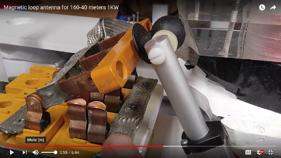
Alex. Loop Butterfly Tuning Capacitor Butterfly style reduces contact losses 3 KV requires 0. 12 in. spacing Mechanical connections ? ? ?
 Frequency: 7 MHz Transmitter Power: 100")
Conductor Diameter Circumference: 9 ft (~3 ft diameter) Frequency: 7 MHz Transmitter Power: 100 W Diameter of Conductor: 2. 0 in Antenna efficiency: 20% (-6. 9 d. B below 100%) Antenna bandwidth: 2. 01 k. Hz Tuning Capacitance: 220 p. F Capacitor voltage: 5, 999 volts RMS Resonant circulating current: 58. 0 A Radiation resistance: 0. 003 ohms Loss Resistance: 0. 012 ohms Quality Factor (Q): 3, 476 Diameter of Conductor: 3. 0 in Antenna efficiency: 28% (-5. 6 d. B below 100%) Antenna bandwidth: 1. 35 k. Hz Tuning Capacitance: 201 p. F Capacitor voltage: 7, 658 volts RMS Resonant circulating current: 67. 6 A Radiation resistance: 0. 003 ohms Freq drift due Loss Resistance: 0. 008 ohms to heating? ? Quality Factor (Q): 5, 178 1) At 7 MHz the circumference should be between 17 and 34 feet 2) Conductors can be too small or too large 3) An air variable with 0. 25 in plate spacing is only good

Loop Size Diameter of Conductor: Frequency: Transmitter Power: 2. 0 in 7. 0 MHz 1000 W Circumference: 9 ft (~3 ft diameter) Circumference: 38 ft (~12 ft diameter) Antenna efficiency: 20% (-6. 9 d. B below 100%) Antenna bandwidth: 2. 01 k. Hz Tuning Capacitance: 220 p. F Capacitor voltage: 18, 970 volts RMS Resonant circulating current: 183 A Radiation resistance: 0. 003 ohms Loss Resistance: 0. 012 ohms Quality Factor (Q): 3, 476 Antenna efficiency: 95% (-0. 2 d. B below 100%) Antenna bandwidth: 24. 3 k. Hz Tuning Capacitance: 39 p. F Capacitor voltage: 12, 954 volts RMS Resonant circulating current: 22. 2 A Radiation resistance: 0. 963 ohms Loss Resistance: 0. 050 ohms Quality Factor (Q): 288 Circumference should be between 17 and 34 feet

N 4 MQ

Frequency Circumference: Diameter of Conductor: Transmitter Power: Frequency: 1. 8 MHz Antenna efficiency: 9% (-10. 7 d. B below 100%) Antenna bandwidth: 1. 32 k. Hz Tuning Capacitance: 655 p. F Capacitor voltage: 13, 584 volts RMS (19, 200 volts PEAK) Resonant circulating current: 101 A Radiation resistance: 0. 004 ohms Loss Resistance: 0. 045 ohms Quality Factor (Q): 1, 367 Circumference should be between 66. 3 and 133 feet 38 ft (12 ft diameter) 1. 125 in 1000 W Frequency: 7. 0 MHz Antenna efficiency: 92% (-0. 4 d. B below 100%) Antenna bandwidth: 28. 1 k. Hz Tuning Capacitance: 43 p. F Capacitor voltage: 11, 440 volts RMS Resonant circulating current: 21. 8 A Radiation resistance: 0. 963 ohms Loss Resistance: 0. 089 ohms Quality Factor (Q): 249 Circumference should be between 17 and 34 feet

Only capable of 300 W with 15 KV caps Russian caps -Both rated for 45 KV -? Amp rating

>20 KV

18 inches tall

RF Impedance of Flat Conductors • RF current density is highest at the points where the curvature is greatest. RED = Large current BLUE = Small current EETimes: Power Tip 26: Current distribution in high-frequency conductors https: //www. eetimes. com/document. asp? doc_id=1278215
 40 -10 M")
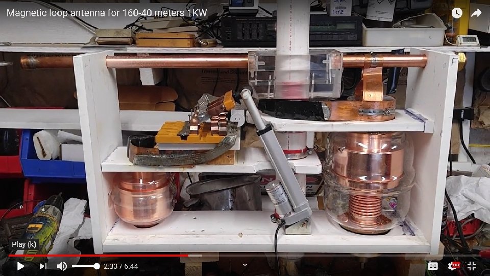
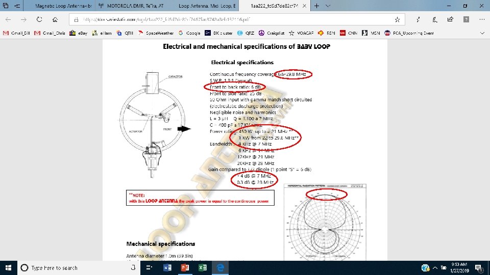
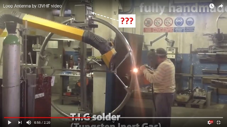
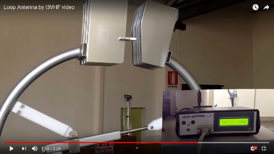
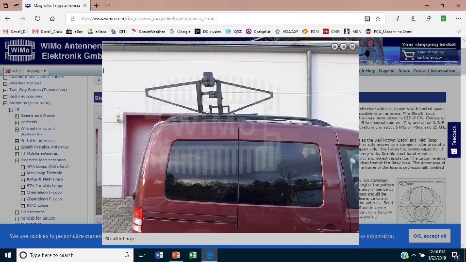
Commercial High Power Mag Loops • Cirro Mazzoni (I 3 VHF) 40 -10 M 450 -1000 W $2100 80 -20 M 300 -800 W $2500 Sold by DX Engineering 40 -10 M 125 W $1800
 A. T. U.")
Commercial High Power Mag Loops • Cirro Mazzoni (I 3 VHF) A. T. U. 2. 0 (Automatic Tuner Unit)

Equivalent. Circuit Crcuit
- Slides: 22