
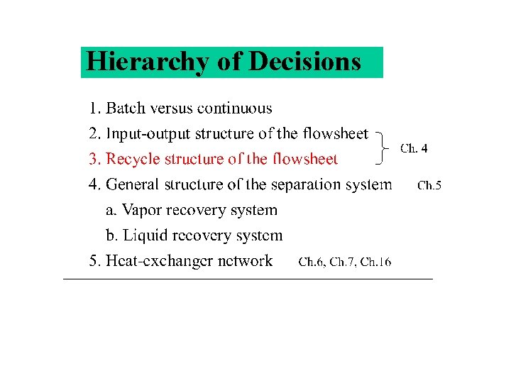
Hierarchy of Decisions Purge H 2 CH 4
- Slides: 31
Hierarchy of Decisions
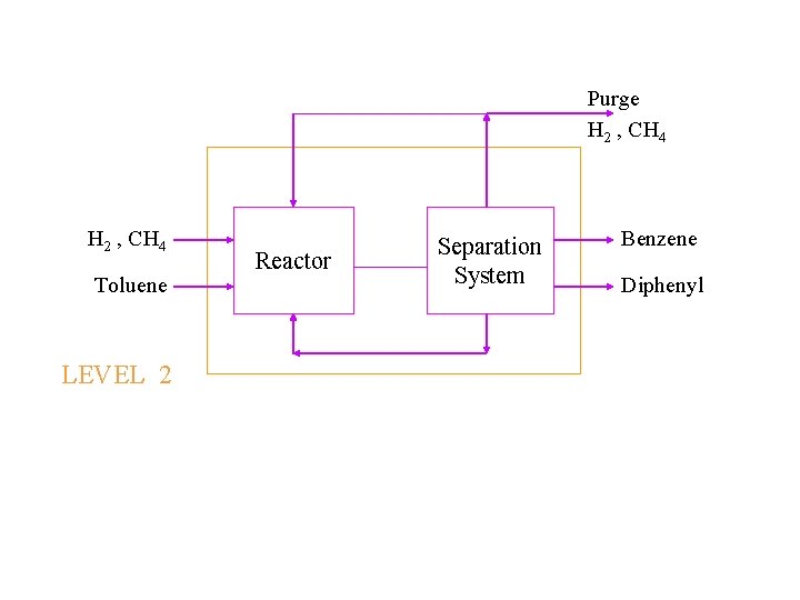
Purge H 2 , CH 4 Toluene LEVEL 2 Reactor Separation System Benzene Diphenyl
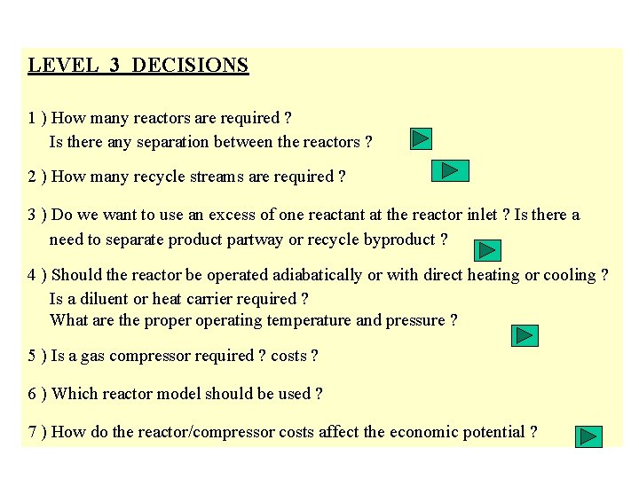
LEVEL 3 DECISIONS 1 ) How many reactors are required ? Is there any separation between the reactors ? 2 ) How many recycle streams are required ? 3 ) Do we want to use an excess of one reactant at the reactor inlet ? Is there a need to separate product partway or recycle byproduct ? 4 ) Should the reactor be operated adiabatically or with direct heating or cooling ? Is a diluent or heat carrier required ? What are the properating temperature and pressure ? 5 ) Is a gas compressor required ? costs ? 6 ) Which reactor model should be used ? 7 ) How do the reactor/compressor costs affect the economic potential ?
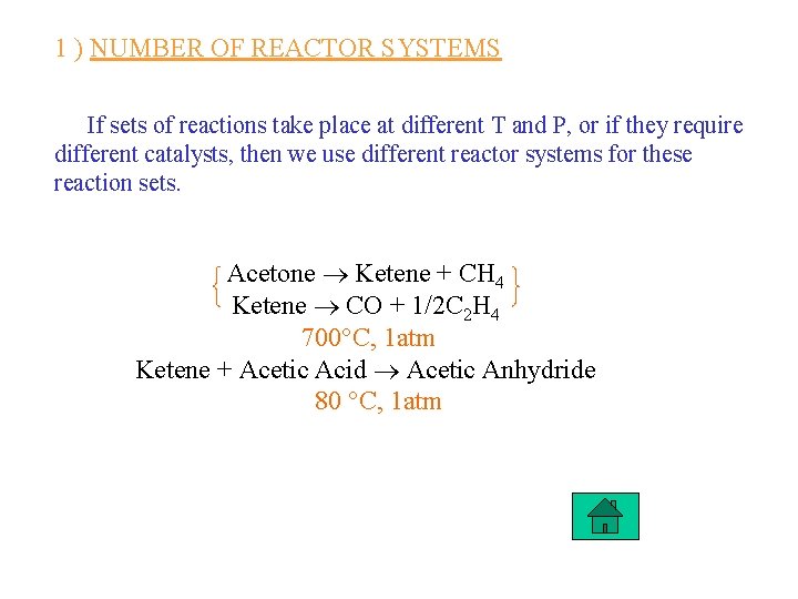
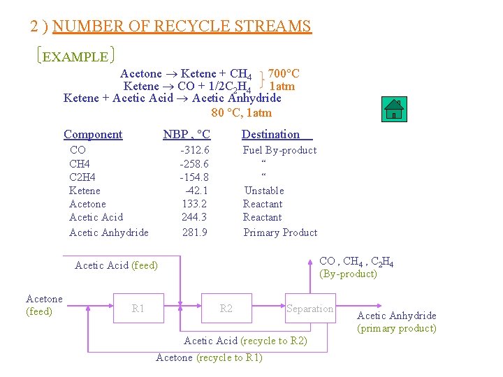
1 ) NUMBER OF REACTOR SYSTEMS If sets of reactions take place at different T and P, or if they require different catalysts, then we use different reactor systems for these reaction sets. Acetone Ketene + CH 4 Ketene CO + 1/2 C 2 H 4 700 C, 1 atm Ketene + Acetic Acid Acetic Anhydride 80 C, 1 atm
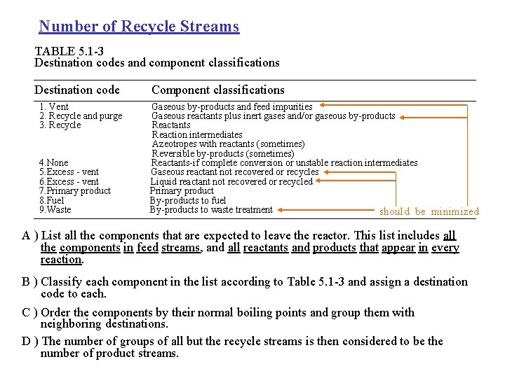
Number of Recycle Streams TABLE 5. 1 -3 Destination codes and component classifications Destination code 1. Vent 2. Recycle and purge 3. Recycle 4. None 5. Excess - vent 6. Excess - vent 7. Primary product 8. Fuel 9. Waste Component classifications Gaseous by-products and feed impurities Gaseous reactants plus inert gases and/or gaseous by-products Reactants Reaction intermediates Azeotropes with reactants (sometimes) Reversible by-products (sometimes) Reactants-if complete conversion or unstable reaction intermediates Gaseous reactant not recovered or recycles Liquid reactant not recovered or recycled Primary product By-products to fuel By-products to waste treatment should be minimized A ) List all the components that are expected to leave the reactor. This list includes all the components in feed streams, and all reactants and products that appear in every reaction. B ) Classify each component in the list according to Table 5. 1 -3 and assign a destination code to each. C ) Order the components by their normal boiling points and group them with neighboring destinations. D ) The number of groups of all but the recycle streams is then considered to be the number of product streams.
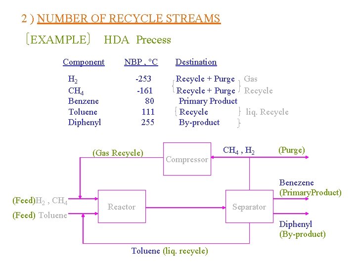
2 ) NUMBER OF RECYCLE STREAMS EXAMPLE HDA Precess Component H 2 CH 4 Benzene Toluene Diphenyl NBP , C -253 -161 80 111 255 (Gas Recycle) (Feed)H 2 , CH 4 (Feed) Toluene Destination Recycle + Purge Gas Recycle + Purge Recycle Primary Product Recycle liq. Recycle By-product Compressor CH 4 , H 2 (Purge) Benezene (Primary. Product) Reactor Separator Diphenyl (By-product) Toluene (liq. recycle)
2 ) NUMBER OF RECYCLE STREAMS EXAMPLE Acetone Ketene + CH 4 700 C Ketene CO + 1/2 C 2 H 4 1 atm Ketene + Acetic Acid Acetic Anhydride 80 C, 1 atm NBP , C Component CO CH 4 C 2 H 4 Ketene Acetone Acetic Acid Acetic Anhydride Destination -312. 6 -258. 6 -154. 8 -42. 1 133. 2 244. 3 281. 9 Fuel By-product “ “ Unstable Reactant Primary Product CO , CH 4 , C 2 H 4 (By-product) Acetic Acid (feed) Acetone (feed) R 1 R 2 Separation Acetic Acid (recycle to R 2) Acetone (recycle to R 1) Acetic Anhydride (primary product)
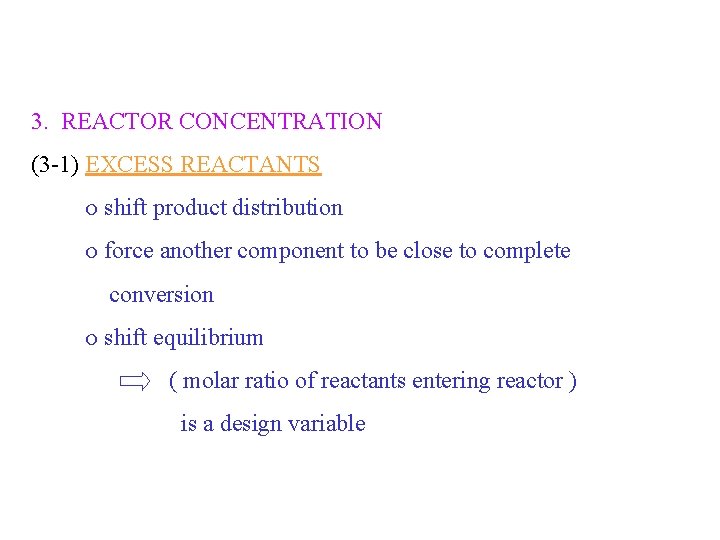
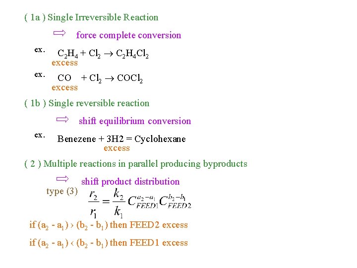
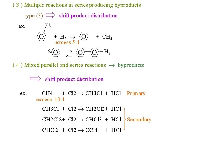
3. REACTOR CONCENTRATION (3 -1) EXCESS REACTANTS shift product distribution force another component to be close to complete conversion shift equilibrium ( molar ratio of reactants entering reactor ) is a design variable
( 1 a ) Single Irreversible Reaction force complete conversion ex. C 2 H 4 + Cl 2 C 2 H 4 Cl 2 excess ex. CO + Cl 2 COCl 2 excess ( 1 b ) Single reversible reaction shift equilibrium conversion ex. Benezene + 3 H 2 = Cyclohexane excess ( 2 ) Multiple reactions in parallel producing byproducts type (3) shift product distribution if (a 2 - a 1) › (b 2 - b 1) then FEED 2 excess if (a 2 - a 1) ‹ (b 2 - b 1) then FEED 1 excess
( 3 ) Multiple reactions in series producing byproducts type (3) ex. shift product distribution CH 3 O + H 2 O excess 5: 1 2 O O + CH 4 O + H 2 ( 4 ) Mixed parallel and series reactions byproducts shift product distribution ex. CH 4 + Cl 2 CH 3 Cl + HCl excess 10: 1 Primary CH 3 Cl + Cl 2 CH 2 Cl 2+ HCl CH 2 Cl 2+ Cl 2 CHCl 3 + HCl CHCl 3 + Cl 2 CCl 4 + HCl Secondary
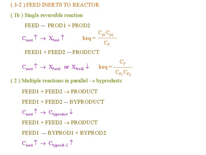
( 3 -2 ) FEED INERTS TO REACTOR ( 1 b ) Single reversible reaction FEED PROD 1 + PROD 2 Cinert Xfeed FEED 1 + FEED 2 keq = Cp 1 Cp 2 CF PRODUCT Cinert Xfeed 1 or Xfeed 2 keq = CP CF 1 CF 2 ( 2 ) Multiple reactions in parallel byproducts FEED 1 + FEED 2 PRODUCT FEED 1 + FEED 2 BYPRODUCT Cinert Cbyproduct FEED 1 + FEED 2 PRODUCT FEED 1 BYPROD 1 + BYPROD 2 Cinert Cbyprod 1 -2
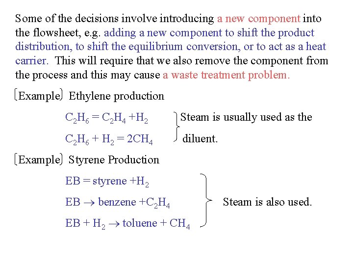
Some of the decisions involve introducing a new component into the flowsheet, e. g. adding a new component to shift the product distribution, to shift the equilibrium conversion, or to act as a heat carrier. This will require that we also remove the component from the process and this may cause a waste treatment problem. Example Ethylene production C 2 H 6 = C 2 H 4 +H 2 Steam is usually used as the C 2 H 6 + H 2 = 2 CH 4 diluent. Example Styrene Production EB = styrene +H 2 EB benzene +C 2 H 4 EB + H 2 toluene + CH 4 Steam is also used.
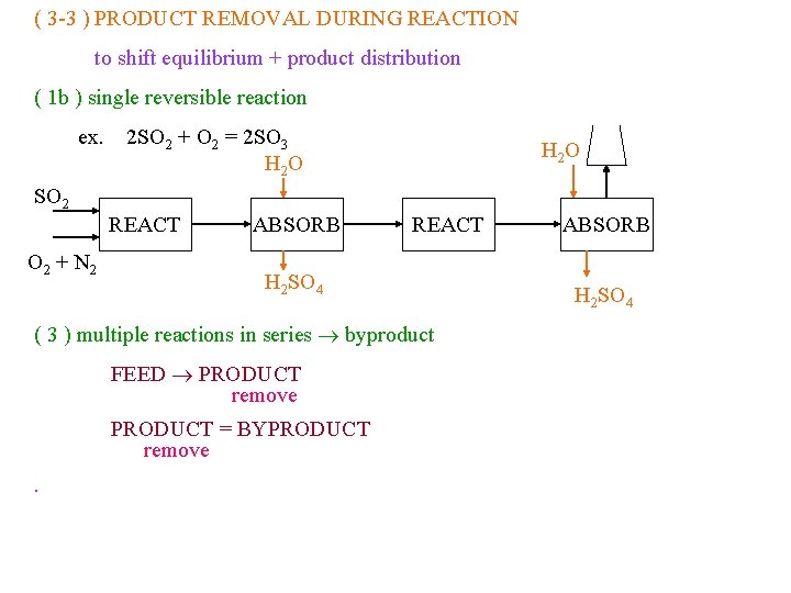
( 3 -3 ) PRODUCT REMOVAL DURING REACTION to shift equilibrium + product distribution ( 1 b ) single reversible reaction ex. 2 SO 2 + O 2 = 2 SO 3 H 2 O SO 2 REACT O 2 + N 2 ABSORB REACT H 2 SO 4 ( 3 ) multiple reactions in series byproduct FEED PRODUCT remove PRODUCT = BYPRODUCT remove. ABSORB H 2 SO 4
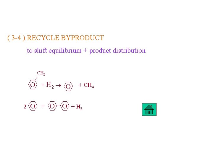
( 3 -4 ) RECYCLE BYPRODUCT to shift equilibrium + product distribution CH 3 O + H 2 O 2 O = O + CH 4 O + H 2
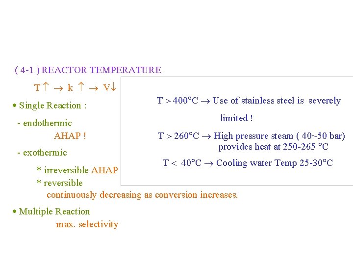
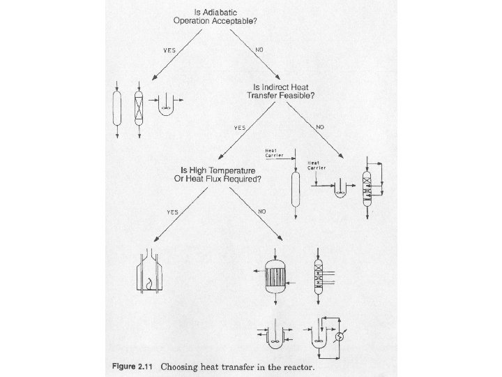
( 4 -1 ) REACTOR TEMPERATURE T k V Single Reaction : - endothermic AHAP ! - exothermic T 400 C Use of stainless steel is severely limited ! T 260 C High pressure steam ( 40~50 bar) provides heat at 250 -265 C T 40 C Cooling water Temp 25 -30 C * irreversible AHAP ! * reversible continuously decreasing as conversion increases. Multiple Reaction max. selectivity
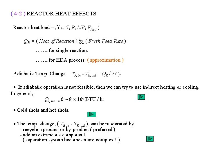
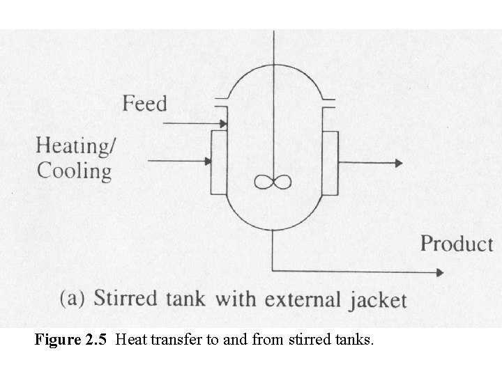
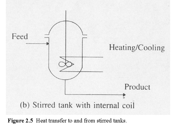
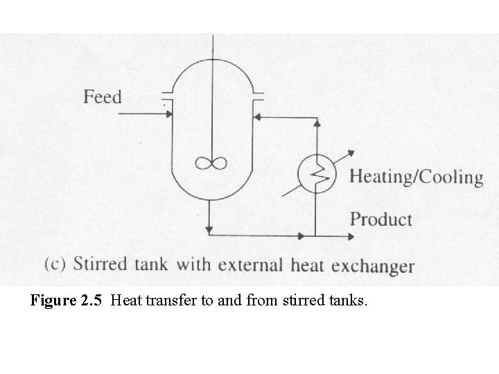
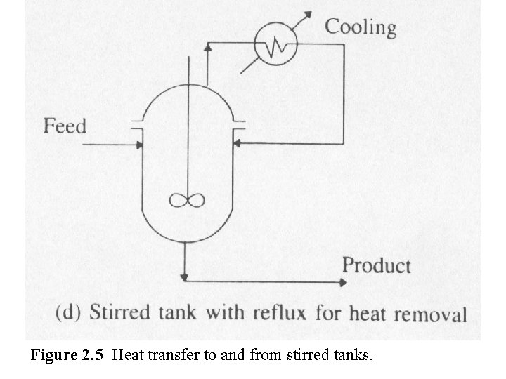
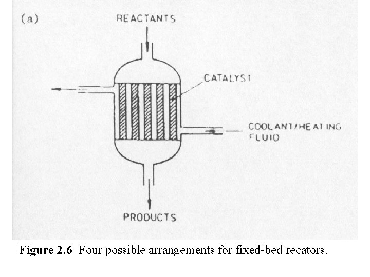
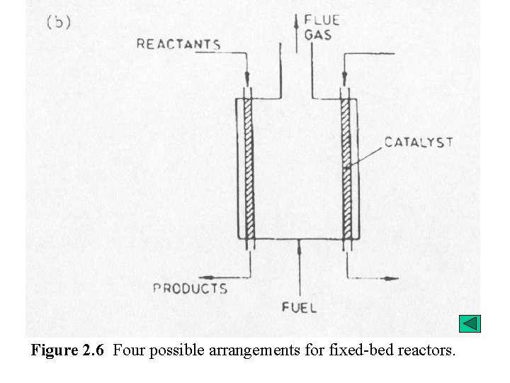
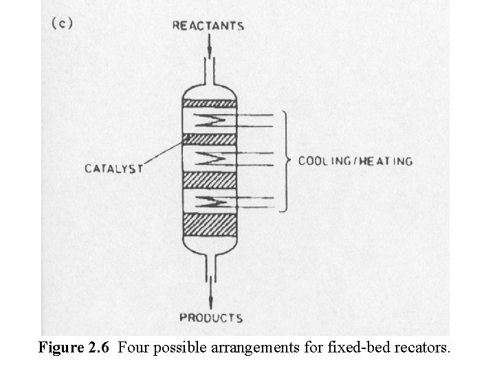
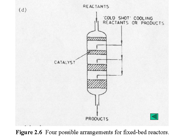
( 4 -2 ) REACTOR HEAT EFFECTS Reactor heat load = f ( x, T, P, MR, Ffeed ) QR = ( Heat of Reaction ) ( Fresh Feed Rate ) ……. . for single reaction. ……. . for HDA process ( approximation ) Adiabatic Temp. Change = TR, in - TR, out = QR / FCP If adiabatic operation is not feasible, then we can try to use indirect heating or cooling. In general, Qt, max 6 ~ 8 106 BTU / hr Cold shots and hot shots. The temp. change, ( TR, in - TR, out ), can be moderated by - recycle a product or by-product ( preferred ) - add an extraneous component. ( separation system becomes more complex ! )
Figure 2. 5 Heat transfer to and from stirred tanks.
Figure 2. 5 Heat transfer to and from stirred tanks.
Figure 2. 5 Heat transfer to and from stirred tanks.
Figure 2. 5 Heat transfer to and from stirred tanks.
Figure 2. 6 Four possible arrangements for fixed-bed recators.
Figure 2. 6 Four possible arrangements for fixed-bed reactors.
Figure 2. 6 Four possible arrangements for fixed-bed recators.
Figure 2. 6 Four possible arrangements for fixed-bed reactors.
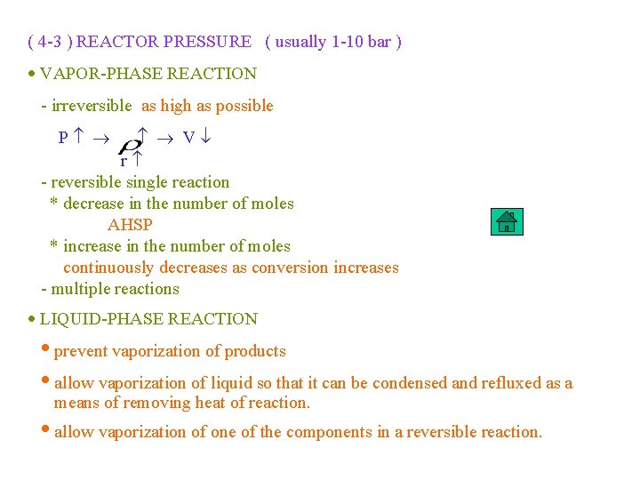
( 4 -3 ) REACTOR PRESSURE ( usually 1 -10 bar ) VAPOR-PHASE REACTION - irreversible as high as possible P V r - reversible single reaction * decrease in the number of moles AHSP * increase in the number of moles continuously decreases as conversion increases - multiple reactions LIQUID-PHASE REACTION prevent vaporization of products allow vaporization of liquid so that it can be condensed and refluxed as a means of removing heat of reaction. allow vaporization of one of the components in a reversible reaction.
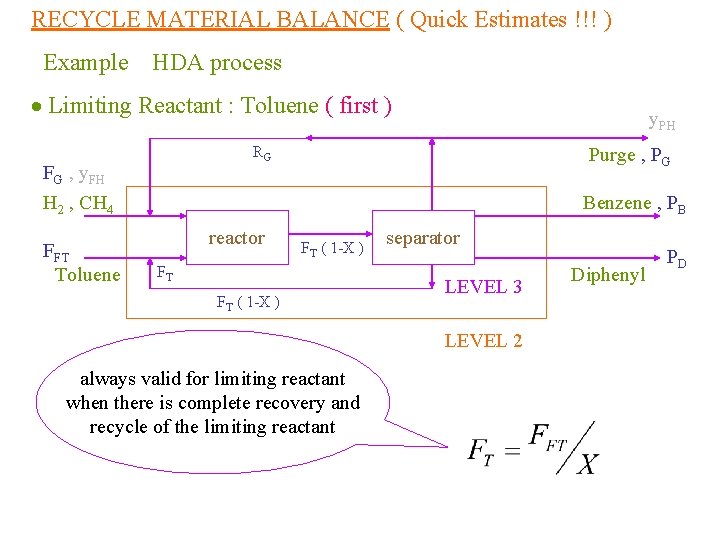
RECYCLE MATERIAL BALANCE ( Quick Estimates !!! ) Example HDA process Limiting Reactant : Toluene ( first ) RG FG , y. FH H 2 , CH 4 FFT Toluene y. PH Purge , PG Benzene , PB reactor FT ( 1 -X ) FT FT ( 1 -X ) separator LEVEL 3 LEVEL 2 always valid for limiting reactant when there is complete recovery and recycle of the limiting reactant Diphenyl PD
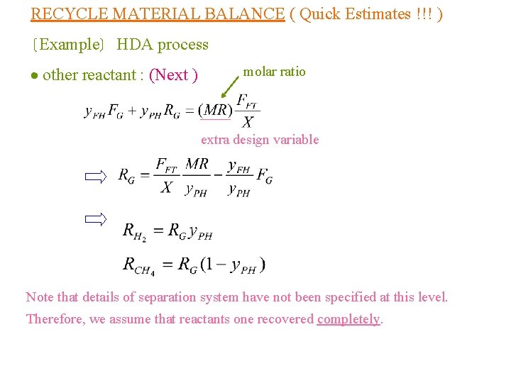
RECYCLE MATERIAL BALANCE ( Quick Estimates !!! ) Example HDA process other reactant : (Next ) molar ratio extra design variable Note that details of separation system have not been specified at this level. Therefore, we assume that reactants one recovered completely.
5 ) COMPRESSOR DESIGN AND COST Whenever a gas-recycle stream is present, we will need a gasrecycle compressor. Covered in “Unit Operation (I)”
6 ) EQUILIBRIUM LIMITATIONS 7 ) REACTOR DESIGN AND COSTS Covered in “Reactor Design and Reaction Kinetics”
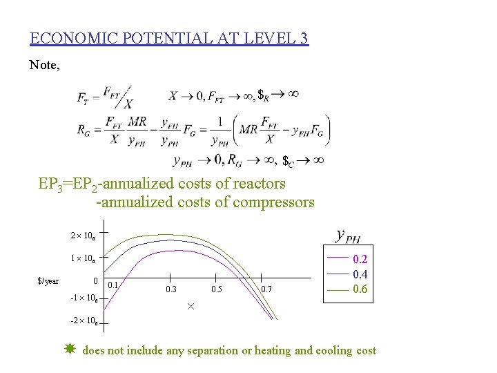
ECONOMIC POTENTIAL AT LEVEL 3 Note, $ $ EP 3=EP 2 -annualized costs of reactors -annualized costs of compressors 2 106 1 106 $/year 0 -1 106 0. 1 0. 3 0. 5 0. 7 0. 2 0. 4 0. 6 -2 106 does not include any separation or heating and cooling cost