HEMODYNAMIC MONITORING In the CRITICAL CARE UNIT M


 § General appearance § Level")


/SVR • SVR = (MAP-CVP)/CO CVP MAP")


 is measured in the")


")


 •")


- Slides: 86
HEMODYNAMIC MONITORING In the CRITICAL CARE UNIT M. MOHSENABADI M. MOHSENIPOUR
What is Hemodynamic Monitoring? It is measuring the pressures in the heart
Why hemodynamic monitoring? • Physicians have developed a psychological dependence on feedback from continuous hemodynamic monitoring tools, independent of their utility • Effectiveness of hemodynamic monitoring to improve outcome limited to specific patient groups and disease processes for which proven effective treatments exist
INDICATIONS § To diagnose shock states § To determine fluid volume status § To measure cardiac output § To monitor and manage unstable patients § To assess hemodynamic response to therapies § To diagnose primary pulmonary hypertension, Valvular disease, intracardiac shunts, cardiac tamponade, and pulmonary embolus
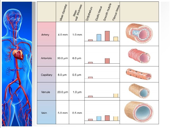
The Blood Vessels and the Cardiovascular System
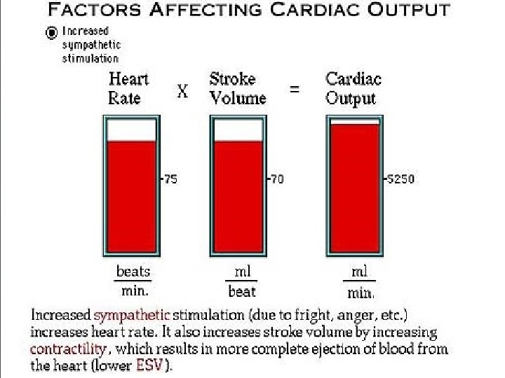
factors that affecting the hemodynamic conditions Myocardial contraction and heart rate Intravascular volume Vasoactivity
The Blood Vessels and the Cardiovascular System § Arteries: blood from heart § Strong & Elastic § Conduct blood to capillaries § Sphincters § Capillaries: exchange with cells § Veins § Return blood to heart § Valves
Arteries endothelium Smooth muscle cell layer adventitia
Veins “Blood Reservoir” 70% of our blood volume is on the venous side.
The pulse is a wave of dilatation
Similar to a surface wave
A heavenly wave
CLINICAL PARAMETERS § Blood pressure § Heart rate and rhythm § Rate of capillary refill of skin after blanching § Urine output § Mental status
Hemodynamic Monitoring § Baseline data obtained (low cardiac output) § General appearance § Level of consciousness § Skin color/temperature § Vital signs § Peripheral pulses § Urine output
Purpose of Hemodynamic Monitoring n. Evaluate cardiovascular system n. Pressure, flow, resistance n. Establish baseline values and evaluate trends n. Determine presence and degree of dysfunction n. Implement and guide interventions early to prevent problems
Hemodynamic Monitoring Components • Heart Rate • Blood Pressure and MAP • CVP • Pulmonary Artery Pressures • Systemic Vascular Pressure (SVR) • Pulmonary Vascular Pressure (PVR) • Cardiac Output/ Cardiac Index • Stroke Volume
Hemodynamic monitoring types: • Invasive • Non Invasive
Hemodynamic Monitoring Non Invasive • • • Clinical variables BP ECG Cardiac Monitoring Echocardiography O 2 saturation
Invasive • CVP • Arterial catheter • Cardiac output • PA Catheter
Types of Invasive Pressure Monitoring § Continuous arterial pressure monitoring § Acute hypertension/hypotension § Respiratory failure § Shock § Neurologic shock § Coronary interventional procedures § Continuous infusion of vasoactive drugs § Frequent ABG sampling
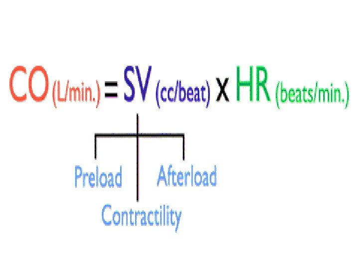
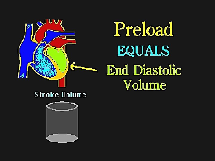
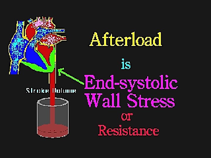
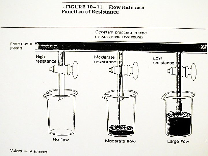
Comparing Hemodynamics to IV pump § Fluid =preload § Pump= CO or contractility (needs electricity) § Tubing =afterload
Best indicator of tissue perfusion. Needs to be at least 60 to perfuse organs
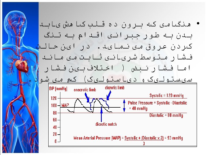
More Blood Pressures: Pulse and Mean Arterial Pressures Figure 15 -5: Pressure throughout the systemic circulation
Mean Arterial Pressure CO • CO = (MAP-CVP)/SVR • SVR = (MAP-CVP)/CO CVP MAP • MAP = (CO x SVR) + CVP SVR
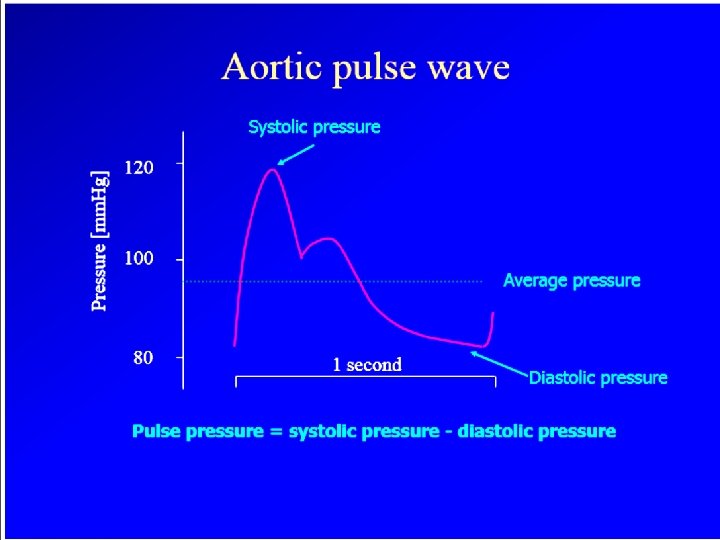
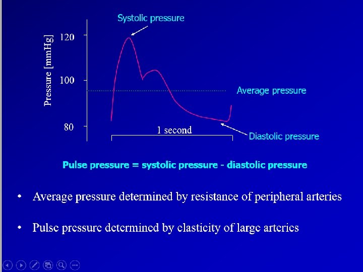
Factors Determining Aortic Pulse Pressure Increased Preload Increased Inotropy Decreased Afterload Increased Stroke Volume Increased Aortic Pulse Pressure Decreased Aortic Compliance Age Arteriosclerosis Hypertension Decreased Heart Rate
Pulse pressure Reflects difference in volume ejected from LV into arterial vessels and volume that exits simultaneously Wide PP – increase in SV and decrease in SVR Narrow PP – Decreased SV and increased SVR
• Pulse pressure – Reflects difference in volume ejected from LV into arterial vessels and volume that exits simultaneously – Wide PP – increase in SV and decrease in SVR – Narrow PP – Decreased SV and increased SVR BP= cardiac output x peripheral vascular resistance CO = (MAP-CVP)/SVR
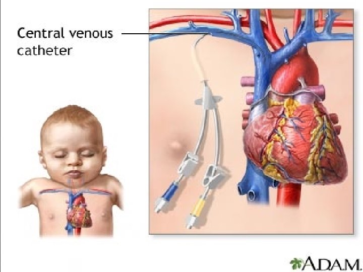
CENTRAL VENOUS PRESSURE MONITORING
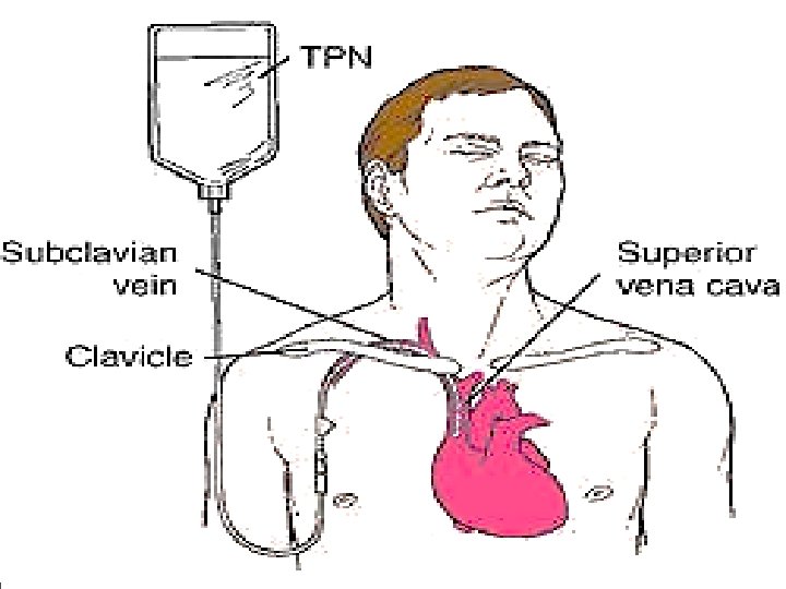
What is CVP ? § The central venous pressure (CVP) is measured in the central veins close to the heart. the pressure It indicates mean right atrial pressure and is frequently used as an estimate of right ventricular preload. § CVP reflects the amount of blood returning to the heart and the ability of the heart to pump the blood into the arterial system. § It is the pressure measured at the junction of the superior vena cava and the right atrium.
CENTRAL VENOUS PRESSURE MONITORING
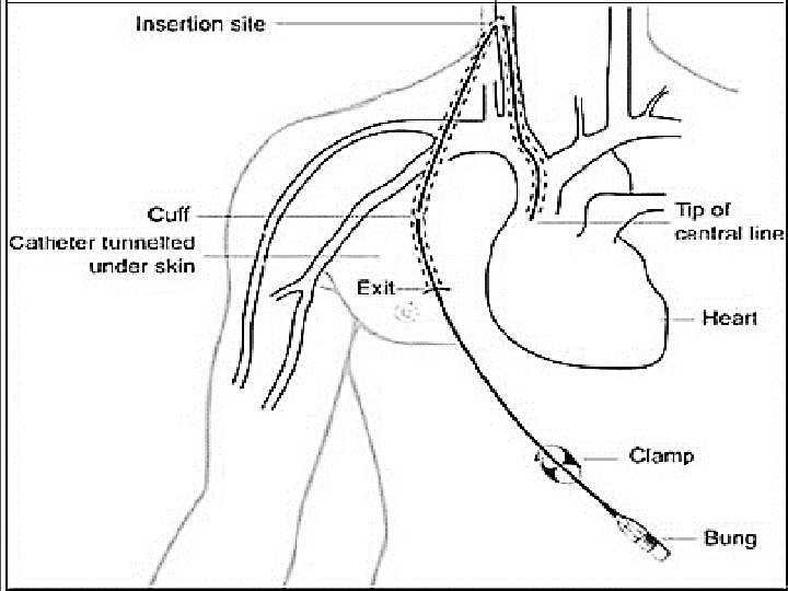
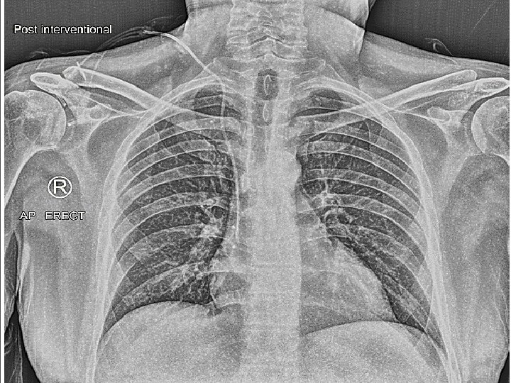
Diagram of placement of central venous catheter: the catheter is tunnelled under skin and enters the superior vena cava into the right side of the heart
Tunneled CVC
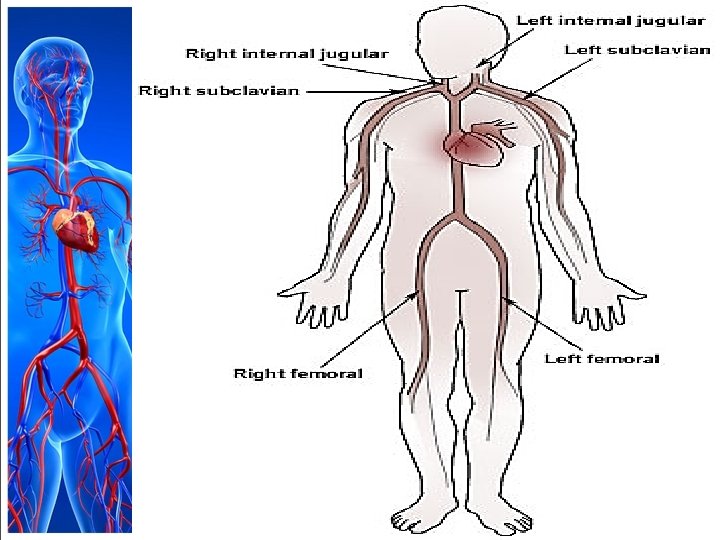
INDICATIONS FOR CENTRAL VENOUS CANNULATION § § § Central venous pressure monitoring Pulmonary artery catheterization & monitoring Trans venous cardiac pacing Temporary hemodialysis Drug administration § Concentrated Vasoactive drugs § Hyper alimentation § Chemotherapy § Agents irritating to peripheral veins § Prolong antibiotic therapy
INDICATIONS CONTD…… § Rapid infusion of fluids § Trauma § Major surgery § Aspiration of air emboli § Inadequate peripheral intravenous access § Sampling site for repeated blood testing
CENTRAL VENOUS PRESSURE MONITORING § In central venous pressure monitoring, the physician inserts a catheter through a vein and advances it until its tip lies in or near the right atrium. § Because no major valves lie at the junction of the vena cava and right atrium, pressure at end diastole reflects back to the catheter. § When connected to a manometer, the catheter measures central venous pressure (CVP), an index of right ventricular function. § CVP monitoring helps to assess cardiac function, to evaluate venous return to the heart, and to indirectly gauge how well the heart is pumping. § The central venous (CV) line also provides access to a large vessel for rapid, high-volume fluid administration and allows frequent blood withdrawal for laboratory samples.
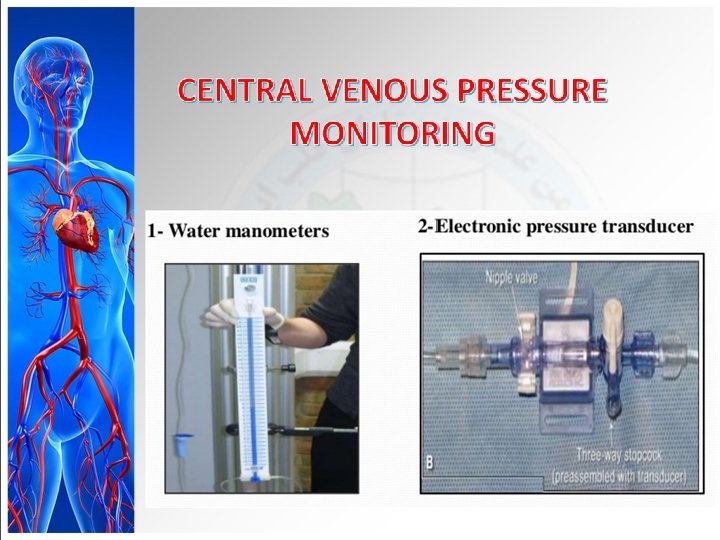
Methods to measure CVP Indirect assessment: § Inspection of jugular venous pulsations in the neck. Direct assessment: § Fluid filled manometer connected to central venous catheter. § Calibrated transducer.
CENTRAL VENOUS PRESSURE MONITORING § CVP monitoring can be done intermittently or continuously. § The catheter is inserted percutaneously or using a cutdown method. § Typically, a single lumen CVP line is used for intermittent pressure readings. § To measure the patient’s volume status, a disposable plastic water manometer is attached between the I. V. line and the central catheter with a three- or four-way stopcock. § CVP is recorded in centimeters of water (cm H 2 O) or millimeters of mercury (mm Hg) read from manometer markings. § Normal CVP ranges from 5 to 10 cm H 2 O or 2 to 6 mm Hg. How many cm. H 2 O in 1 mm. Hg? The answer is 1. 35951002636.
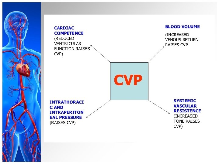
CENTRAL VENOUS PRESSURE MONITORING • Any condition that alters venous return, circulating blood volume, or cardiac performance may affect CVP. • If circulating volume increases (such as with enhanced venous return to the heart), CVP rises. • If circulating volume decreases (such as with reduced venous return), CVP drops.
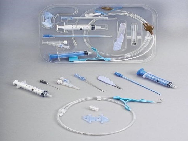
Equipments • For intermittent CVP monitoring: Disposable CVP manometer set leveling device (such as a rod from a reusable CVP pole holder or a carpenter’s level or rule) additional stopcock (to attach the CVP manometer to the catheter) extension tubing (if needed) I. V. pole I. V. solution I. V. drip chamber and tubing dressing materials tape. • For continuous CVP monitoring: Pressure monitoring kit with disposable pressure transducer leveling device bedside pressure module continuous I. V. flush solution 1 unit/1 to 2 ml of heparin flush solution pressure bag. • For withdrawing blood samples through the CV line: • Appropriate number of syringes for the ordered tests 5 - or 10 -ml syringe for the discard sample. (Syringe size depends on the tests ordered. ) • For using an intermittent CV line: Syringe with normal saline solution syringe with heparin flush solution. • For removing a CV catheter: Sterile gloves suture removal set sterile gauze pads povidone-iodine ointment dressing tape.
Implementation • Gather the necessary equipment. • Explain the procedure to the patient to reduce his anxiety. • Assist the physician as he inserts the CV catheter. • (The procedure is similar to that used for pulmonary artery pressure monitoring, except that the catheter is advanced only as far as the superior vena cava. )
MEASURING CVP WITH A WATER MANOMETER • To ensure accurate central venous pressure (CVP) readings, make sure the manometer base is aligned with the patient’s right atrium (the zero reference point). • The manometer set usually contains a leveling rod to allow you to determine this quickly. • After adjusting the manometer’s position, examine the typical three-way stopcock. • By turning it to any position shown at right, you can control the direction of fluid flow. • Four-way stopcocks also are available.
Relationship between water manometer and calibrated transducer : Normal CVP ranges from 5 to 10 cm H 2 O or 2 to 6 mm Hg. In terms of pressure 1 cm H 2 O = 0. 73 mm. Hg. 1 mm. Hg = 1. 36 cm H 2 O.
Phlebostatic Axis • 4 th intercostal space, mid-axillary line • Level of the atria 66
cvp zeroing
More on Leveling and Zeroing • HOB 0 – 60 degrees • No lateral positioning • Phlebostatic axis with any position (dotted line)
• All openings blocked
• Manometer to patient
• I. V. solution to manometer
• I. V. solution to patient
I. V. solution bottle Manometer Zero point Three-way stopcock
• Verify that the water manometer is connected to the I. V. tubing. Typically, markings on the manometer range from – 2 to 38 cm H 2 O. • However, manufacturer’s markings may differ, so be sure to read the directions before setting up the manometer and obtaining readings. Turn the stopcock off to the patient, and slowly fill the manometer with I. V. solution until the fluid level is 10 to 20 cm H 2 O higher than the patient’s expected CVP value. • Don’t overfill the tube because fluid that spills over the top can become a source of contamination. •
Obtaining continuous CVP readings with a pressure monitoring system • Make sure the CV line or the proximal lumen of a pulmonary artery catheter is attached to the system. • (If the patient has a CV line with multiple lumens, one lumen may be dedicated to continuous CVP monitoring and the other lumens used for fluid administration. ) • Set up a pressure transducer system. • Connect noncompliant pressure tubing from the CVP catheter hub to the transducer. Then connect the flush solution container to a flush device. • To obtain values, position the patient flat. • If he can’t tolerate this position, use semi-Fowler’s position.
• Locate the level of the right atrium by identifying the phlebostatic axis. • Zero the transducer, leveling the transducer air-fluid interface stopcock with the right atrium. • Read the CVP value from the digital display on the monitor, and note the waveform. • Make sure the patient is still when the reading is taken to prevent artifact. • Be sure to use this position for all subsequent readings.
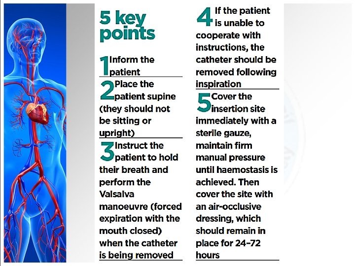
Removing a CV line • You may assist the physician in removing a CV line. • (In some states, a nurse is permitted to remove the catheter with a physician’s order or when acting under advanced collaborative standards of practice. ) • If the head of the bed is elevated, minimize the risk of air embolism during catheter removal—for instance, by placing the patient in Trendelenburg’s position if the line was inserted using a superior approach. • If he can’t tolerate this, position him flat.
Removing a CV line • Clean the insertion site, apply povidone-iodine ointment, and cover it with a dressing as ordered. • Assess the patient for signs of respiratory distress, which may indicate an air embolism.
Complications of CVP monitoring include: • pneumothorax (which typically occurs upon catheter insertion) • sepsis • thrombus • vessel or adjacent organ puncture, and air embolism
CVP MONITORING
CVP MONITORING
Dynamic Flush Dynamic flush ensures the integrity of the pressure tubing system. Notice how it ascends forms a square pattern - and bounces below the baseline before returning to the original waveform. • Check dynamic flush after zeroing any pressure tubing system
CVP MONITORING
CVP MONITORING
CVP MONITORING
Documentation • Document all dressing, tubing, and solution changes. • Document the patient’s tolerance of the procedure • the date and time of catheter removal, and the type of dressing applied. • Note the condition of the catheter insertion site and whether a culture specimen was collected. • Note any complications and actions taken.