Hemodynamic Monitoring Atrerial Line CVP Line NSG 409


: is the amount of")
 is the amount of resistance")


 are transmitted through the catheter and Fluid filled non")


: • Normal range 70 -105 mm. Hg. • MAP is")
![Example MAP = [SP + (DP * 2)] / 3 For example, if BP=](https://slidetodoc.com/presentation_image_h/20672fbb6e3add8b64e8480e4ac41753/image-56.jpg "Example MAP = [SP + (DP * 2)] / 3 For example, if BP=")


![Central Venous Pressure[CVP] Monitoring • CVP is pressure of blood in the right atrium](https://slidetodoc.com/presentation_image_h/20672fbb6e3add8b64e8480e4ac41753/image-69.jpg "Central Venous Pressure[CVP] Monitoring • CVP is pressure of blood in the right atrium")


 BLOOD VOLUME (increased venous")


 –")


- Slides: 106
Hemodynamic Monitoring Atrerial Line & CVP Line NSG 409 Fall 2016 -2017
Hemodynamic Monitoring Is a means of evaluating: q. Intracardiac and intravascular volume. q. Intracardiac and intravascular pressure. q. Cardiac function at bedside.
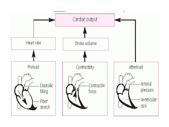
Preload also known as the left ventricular enddiastolic pressure (LVEDP): is the amount of ventricular stretch at the end of diastole.
Afterload, also known as the systemic vascular resistance (SVR) is the amount of resistance the heart must overcome to open the aortic valve and push the blood volume out into the systemic circulation.
Frank-starling mechanism states that the stroke volume of the heart increases in response to an increase in the volume of blood filling the heart (the end diastolic volume) when all other factors remain constant.
Frank-starling mechanism
TABLE 5– 2 Causes of Elevated and Decreased Preload
TABLE 5– 3 Causes of Elevated and Decreased Afterload
TABLE 5– 4 Causes of Elevated and Decreased Contractility
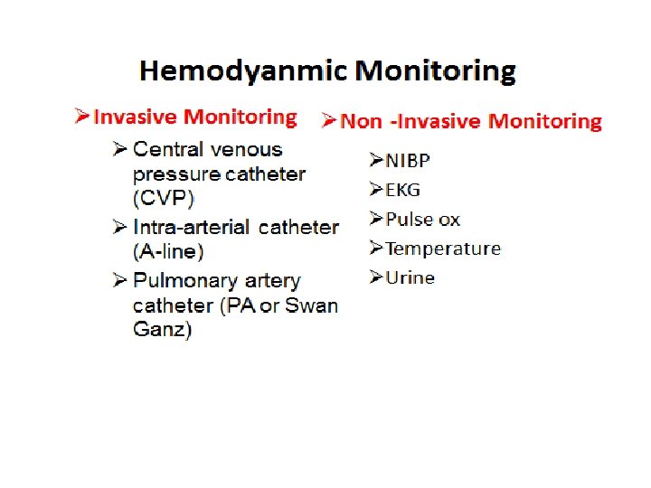
Hemodynamic Monitoring
Pressure monitoring system • Equipments – A hollow tube catheter – Fluid filled pressure monitoring system, comprised of flush solution – IV tubing with drip chamber – Non compliant tubing – Stopcocks – A flush device – One or more transducers – A monitor to display pressures and wave lines CONFIDENTIAL 22
Pressure from the (Intravascular/cardiac chambers) are transmitted through the catheter and Fluid filled non complaint tubing to pressure transducer, which then converts the physiological signal from the patient into an electrical one. The monitor converts and amplifies the electrical signal generated by the transducer to a pressure tracing and digital value Pressure from the (Intravascular/cardiac chambers) catheter and Fluid filled non complaint tubing transducer monitor CONFIDENTIAL 23
24
How to set an A-line/Cvp line https: //www. youtube. com/watch? v=v. J_an. Wm Qb. UM https: //www. youtube. com/watch? v=GXg. EANcx. Dc
Assess Pressure System Component • A continuous Flush system maintain a patent pressure system. • Normal Saline (NS) or Dextrose –Water (D 5 W) & may be heparinzned. • Bag of solution is placed into a continuous infusion pressure bag that exerts approximately 300 mm. Hg. • Flow of 3 -5 ml per Hour, to prevent backflow of blood through the catheter tubing. CONFIDENTIAL 26
• Stopcocks, used for ZEROING the transducer and blood sampling, as well as any other connectors. • A pressure transducer senses changes in the fluid column generated by the pressures in the cardiac chambers or vessels being monitored. • When pressure is applied to the diaphragm of the transducer, sensors are compressed, changing electrical flow to the amplifier or monitor. CONFIDENTIAL 27
Optimizing pressure monitoring system • An optimal pressure monitoring system is one that accurately reproduce the physiological signals transmitted through it (accurate pressure recording and waveform display). • Improper set-up and equipment malfunction are the primary causes for hemodynamic monitoring problems CONFIDENTIAL 28
Optimizing pressure monitoring system • Pressure Readings might be altered by – Any impedance between patient and transducers i. e. air bubbles, blood, additional stopcocks. – Pressure in the continuous pressure device < 300 mm. Hg , soft complaint IV tubing, additional length of tubing. (See table 17 -16 p. 297 for troubleshooting) CONFIDENTIAL 29
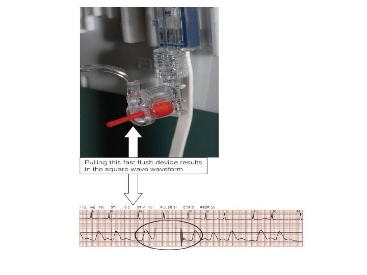
Square Wave Test Fast Flush: Dynamic response testing • “fast-flush” or “square wave” test • Performed by opening the continuous flush valve rapidly for several seconds creating a square wave • The nurse performs this test to detect if the abnormal wave form is a result of the pt’s physiology OR less Optimized system !!!? ? ? • If dynamic response characteristics are inadequate, troubleshoot the system until acceptable dynamic response is achieved CONFIDENTIAL 30
Fast flush system Optimally Damped System • A good art line trace has a distinct dicrotic notch, and after the fast flush, the rhythm will return to the baseline waveform within “ 1. 5 to 2 oscillations close together” 31
Fast flush system Optimally Damped System • Straight vertical upstroke from baseline horizontal straight vertical downstroke ending with 1 -1. 5 oscillations baseline • A good art line trace has a distinct dicrotic notch, and after the fast flush test there are two oscillations only. • Distance is very close
Fast flush system Underdamped System • The under-damped trace will overestimate the systolic, and there will be more than 2 to 3 oscillations above and below the baseline. CONFIDENTIAL 33
Fast flush system Underdamped System • Causes include small air bubbles, very rigid pressure tubing, and additional length of tubing • produce artificially high systolic pressures and low diastolic pressure CONFIDENTIAL 34
Fast flush system Overdamped System • The over-damped trace will lose its dicrotic notch, and there will be less than 1. 5 oscillation above and below the baseline. CONFIDENTIAL 35
Fast flush system Overdamped System • Causes include system leaks, blood clot, or large air bubble in the tubing or transducer. • produce artificially low systolic pressures and low diastolic pressure CONFIDENTIAL 36
Question • To ensure accurate arterial pressures, the nurse must level the transducer to what landmark? – A. Nipple line – B. Phlebostatic axis – C. Sternal notch – D. Apical impulse
Answer • B. Phlebostatic axis • Rationale: The phlebostatic axis is between the fourth intercostal space and midaxillary line; this is the approximate location of the right atrium.
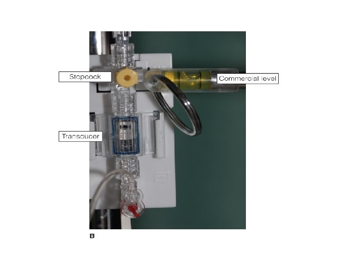
Leveling • To ensure accurate pressure monitoring: System is leveled to external landmark (Phlebostatic Axis : bisection of the 4 th ICS & Midpoint of A-P chest diameter. • Typically , The stopcock nearest to the transducer is used to leveling and zeroing ! Zero Reference Point 39
Leveling continue…. • Transducer placed above the reference point produces falsely low readings • conversely a transducer below the reference point produces falsely high readings. • Every inch the transducer is above or below the reference point produces a 2–mm Hg change in pressure reading. CONFIDENTIAL 40
Leveling
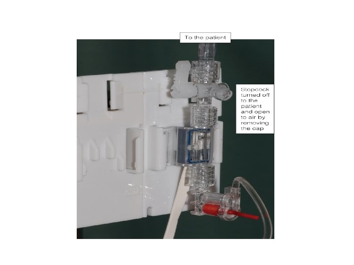
Zeroing • Is the action of opening the pressure system to the atmosphere and observing the reading of ZERO on the monitor • The patient is placed on his or her back, and the head of the bed may be elevated as much as 60 degrees. With a carpenter-type level or laserlight level device, the transducer is placed even with the preestablished zero reference point. • Zeroing involves opening the system to the air to establish atmospheric pressure as zero. • https: //www. youtube. com/watch? v=_gu. FANs. GB_I CONFIDENTIAL 43
0 = None Open to Air Off CONFIDENTIAL 44
Arterial line
Arterial Line • Allows continuous monitoring of systemic arterial BP. • Provides Vascular access for obtaining blood samples by withdrawing blood from stopcock • Indications for intra-arterial BP monitoring include: monitoring Pts with vasoactive IV infusion; requires frequent arterial blood sampling and laboratory; Pts with cardiovascular instability; & fluctuating, unstable blood pressure. CONFIDENTIAL 48
Sites of Insertion • Most Common – Radial artery – Brachial artery – Femoral artery • Less Common – Axilliary & Dorsalis Pedis in adults – Or in neonates (temporal &umbilical) CONFIDENTIAL 49
Factors To Consider In AL • Size of artery should be large enough to accommodate catheter without impeding blood flow • Accessibility: easily accessible and free from contamination • Blood flow to limb distal to insertion site adequate co-lateral circulation in the event that the canulated artery becomes occluded Pressure monitoring system is assessed, and transducer is leveled and zeroed before catheter is inserted. CONFIDENTIAL 50
Radial Artery • Most commonly used • Easily to palpate and poses the least limitation to pt’s mobility. • Allen’s Test ! (Video) – < 7 Seconds : adequate circulation) – 7 -15 Seconds possible impairment – > 15 Seconds inadequate circulation NO CANNULATION !!! 51
52
Arterial Pressure Waveform Analysis • The arterial waveform reflects the pressure generated in the arteries following ventricular contraction and can be described as having: - a rapid upstroke, a clear dicrotic notch, and a definite end diastolic. – Anacrotic notch – Peak systolic pressure – Dicrotic notch – Diastolic pressure CONFIDENTIAL 53
Arterial Pressure Waveform Analysis • The initial sharp upstroke of the waveform results partly from the rapid ejection of blood from the lt ventricle into Aorta, the QRS complex precedes the rapid rise in arterial pressure. • The dicrotic notch reflects a slight backflow of blood in the aorta, reflecting closure of the aortic valve. • Dicrotic notch corresponds with the end of ventricular repolarization and the T wave on the ECG. CONFIDENTIAL 54
CONFIDENTIAL 55
SBP = 90 -140 mm. Hg DBP = 60 -90 mm. Hg Mean arterial pressure= (N 70 -105 mm. Hg ) Pulse pressure (30 - 100)= SBP – DBP (Indirect refection to the stroke volume) Wide Pulse pressure elevated SBP(i. e aortic regurgitation Narrowed Pulse pressure hypovolumic CONFIDENTIAL 56 status
Mean Arterial Pressure (MAP): • Normal range 70 -105 mm. Hg. • MAP is valuable because it indicates the perfusion pressure; if less than 70 or more than 105 it severely affect vital organs perfusion negatively. • MAP = (CO x SVR); but CO = Hr X SV, therefore, • MAP = Hr x SVR
Example MAP = [SP + (DP * 2)] / 3 For example, if BP= 120/80; MAP = [120 + (2 x 80)]/3; (120 + 160)/3= 280/3= 93 MAP = DP + [(SP - DP) / 3] For example, if BP= 120/80; MAP = 80 + (120 -80)/3 = 80 + (40/3) = 80 + 13 = 93 mm. Hg CONFIDENTIAL 58
Complications Of Arterial Line –Accidental blood loss –Accidental inter-arterial injection of drugs –Local damage to artery –Infection –Impaired circulation to extremity
Nursing Care v Compare B/P with Cuff pressure v. Intra-Arterial BP is higher 5 -10 mm. Hg than pressures obtained by cuff !!! v. Check alarms (SBP, DBP, MAP). Alarms are set either around a patient’s specific parameter or according to institution policy. Typically, high and low alarms are set for systolic, diastolic , and mean pressures and within 10 -20 mm. Hg of pt’s BP v Make sure that the catheter is PATENT. v NO additional IV solutions or medication should be given through the line. CONFIDENTIAL 60
Nursing Care v. Assess for adequate circulation, sensation, & movement of extremity. v. Tightly secure connections to prevent exsanguination. v. Assess the insertion site for s/s of infection, bleeding, hematoma, & tube kinking. CONFIDENTIAL 61
Nursing Care • Evaluate the pressure system: Ensure that the pressure in the pressure bag is maintained at 300 mm. Hg; stopcocks; air bubbles; bedside monitor functioning properly; & alarms set correctly. • Do not allow the flush bag to empty –To maintain patency of arterial cannula. –To prevent air embolism –To maintain accuracy of blood pressure reading –To maintain accuracy of fluid balance chart –To prevent backflow of blood CONFIDENTIAL 62
Nursing Care • Maintain the transducer level with the patient’s phlebostatic axis (fourth intercostal space midaxillary line) • Monitor colour & temperature of limb distal to arterial line & compare to other limb • In patients with ICP monitoring it is appropriate to level the transducer to the tagus of the ear –In order to correctly calculate cerebral perfusion pressure (CPP). CONFIDENTIAL 63
Nursing Care • Blood and fluid are aspirate from the blood-drawing port or stopcock in an attempt to remove a blood clot, and then the system is flushed using the fast flush device. • Never inject anything into an arterial cannula or arterial line CONFIDENTIAL 64
A-L Removal This is an aseptic procedure Remember universal precautions The procedure should be explained to the patient Take dressing off line Remove arterial line ensuring that the entry site is covered with gauze • Apply digital pressure for at least 5 minutes to ensure haemostasis • Dress site with gauze and micropore • Assess the peripheral circulation as thrombosis can occur after removal • • • CONFIDENTIAL 65
Central Venous Line
Question • Is the following statement True or False? • A central venous catheter measures right atrial pressure, left ventricular end-diastolic pressure, and intravascular blood volume.
Answer • True • Rationale: Central venous catheter terminates in the superior vena cava near the right atrium; it measures right atrial pressures, left ventricular end-diastolic pressure, and intravascular blood volume.
WHAT IS A CENTRAL Venous LINE Ø Indwelling catheter inserted via subclavian, jugular, antecubital, or femoral & positioned in the vena cava close to right atrium Ø Connected to hemodynamic monitoring system Ø Reflects Right atrial pressure and provides information about intravascular blood volume, RVEDP, and Rt ventricular function Ø CVP indirectly reflects LVEDP and function because the Lt and Rt sides of the heart are linked by the pulmonary vascular bed
Central Venous Line • TYPES OF CENTRAL LINE: – Single Lumen – Triple Lumen – Quadruple Lumen – Quintuple Lumen - Inserted under sterile technique(gloves, gown, cap, mask) – Video - Chlorhexidine prep
Central Venous Pressure[CVP] Monitoring • CVP is pressure of blood in the right atrium or vena cava. • It provides information about : q Intravascular blood volume q Right ventricular end-diastolic pressure[RVEDP] q Right ventricular [RVFx]function. • Alteration in CVP measurements – High –LOW • Normal range 5 -8 cm H 2 O if measured by water manometer; 0 -6 mm. Hg if measured by pressure transducer. CONFIDENTIAL 71
Indications for CVP lines – Most common indication: • clients w/ potential or altered fluid status – Fluid resuscitation – Parenteral feeding – Measurement of central venous pressure – Poor venous access – Administration of irritant drugs CONFIDENTIAL 72
THE CVP WAVEFORM • The CVP waveform reflects changes in right atrial pressure during the cardiac cycle a wave: due to the increased arterial pressure during Rt atrial contraction. It correlate with P wave on the ECG. C wave: caused by a slight elevation of the tricuspid valve into the Rt atrium during early ventricular contraction. It correlates with the end of QRS complex on an ECG. .
THE CVP WAVEFORM X wave: caused by the downward movement of the ventricle during systolic contraction. It occurs before the T wave on an ECG. V wave: arises from the pressure generated when the blood filling the Rt atrium comes up against a closed tricuspid valve. It occurs as the T wave is ending on an ECG. Y wave: produced by the tricuspid valve opening in diastole with blood flowing into the Rt ventricle. It occurs before the P wave on an ECG CONFIDENTIAL 74
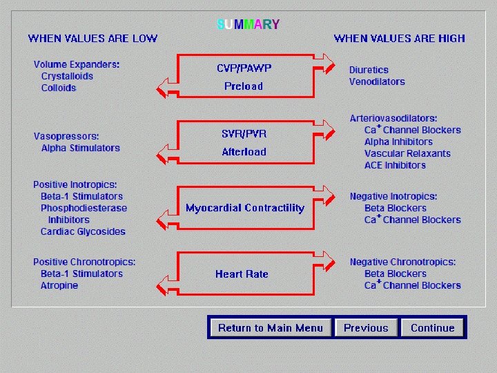
Central Venous Line CARDIAC COMPETENCE (reduced ventricular function raises cvp) BLOOD VOLUME (increased venous return raises cvp Central Venous Pressure CVP INTRATHORACIC AND INTRAPERITONEAL PRESSURE (raises cvp) SYSTEMIC VASCULAR RESISTENCE (increased tone raises cvp)
Nursing Care • Monitoring the system and documentation • Obtain CVP readings hourly (Normal CVP < 8 mm. Hg ) • LOW CVP : • Hypovolemia or pt on diuretic therapy require fluid administration • Sepsis (systemic vasodilatation) • Vasodilating drugs • High CVP – Caused by a number of interrelated factors – Most commonly Right ventricular Failure & Mechanical Ventilator (intrathoracic pressure compress pulmonary vessels resistance to blood flow from the rt side to left side Rt Vent. dysfunction 76
CVP Reading CVP reading is ALWAYS interpreted in conjunction with clinical observation (Lung &heart sounds, HR, RR, ECG, UOP) Left Ventricular Failure ↑CVP , Basilar crackles+ ↓UOP Mechanical Vent Distended neck veins +clear breath sounds + ↑CVP +intrathoracic pressure Sepsis : ↓CVP +fever+ tachycardia +tachypenia +↑WBC Receiving Vasodialting drugs ↓CVP +tachycardia 77
Procedure For CVP Measurement Using A Transducer: • Explain the procedure to the patient • Ensure the line is patent • Position the patient supine (if possible) and align the transducer with the mid axilla (level with the right atrium) • Zero the monitor • Observe the CVP trace • document the reading and report any changes or abnormalities CONFIDENTIAL 78
CVP-Complications • Malposition of the • catheter • • haematoma • arterial puncture • • pneumothorax • • • haemorrhage • sepsis • air emboli Catheter embolism(1020 cc of air Thrombosis Haemothorax Cardiac tamponade Cardiac arrhythmias
Infection • S & S: ü Pain. ü inflammation, or redness at entrance or exit sites, or port site. ü Drainage. ü Elevated WBCs & temperature Nursing Consideration: ü ü ü ü Notify MD. Routine dressing and IV fluid tubing changes Sterile technique during dressing, catheter insertion and removal After catheter removal: Culture (site and catheter tip). Obtain blood cultures as directed by MD or policy. This may include culture from a peripheral vein, central line catheter, or both. Treat fever with prescribed medication. Observe patient for systemic infection. Antibiotic (catheter left in place for long time)
Air embolus : S & S: ü Chest pain, confusion, anxiety ü Cyanosis, unresponsiveness ü Increased blood pressure and/or pulse rate. Decreased CO. Cardiac arrest Nursing Consideration: ü Clamp line & monitor connections ü Place patient on left side with head down (Trendelenburg position). This allow the air to rise to the wall of the Rt ventricle and improve blood flow ü Notify MD. ü Monitor vital signs, ü administer oxygen, ü obtain order to initiate peripheral IV
Dislodgement Of Catheter: -Leakage from catheter or exit site. -Increase or decrease in external catheter length. • Nursing Consideration: ü Secure catheter and extension tubing with tape. ü Observe for absence of suture (if applicable). ü Observe for protrusion of Dacron cuff from exit site. ü Notify physician of findings.
Damaged catheter: • • Leakage from external catheter. Pockets of swelling along catheter path. q Nursing consideration: a. Apply dry sterile dressing below tear and clamp. b. Repair catheter, if applicable, c. assessing the infection risk associated with repair vs. removal. d. Notify physician CONFIDENTIAL 83
Migration of catheter tip: Ø Change in intrathoracic pressure because of coughing, sneezing, or vomiting. Ø Inability to inject fluid Ø Arrhythmias. Ø Patient complaint of "gurgling" sound in ear. Nursing Consideration: ü ü ü CONFIDENTIAL History: gradual or rapid onset? difficult or forceful flush of catheter? ; Notify physician. X-ray to verify position. Discontinue infusion. 84
Thrombosis • S&S: ü Tenderness and edema of neck, shoulder, and/or arm closest to the catheter side. ü Impaired movement of neck and jaw, and Jugular Venous Distention ü Engorged peripheral veins in arm or chest wall. q Nursing Consideration: • Nurse may attempt to aspirate clot if hospital policy permits • Notify physician.
Pinch-off Syndrome • Resistance to flush. Inability to withdraw blood. Flow restored when patient’s position is changed • Nursing consideration: A. Notify physician. B. Obtain chest X-ray to look for catheter compression between the clavicle and the first rib. C. Catheter removal is usually indicated because this compression can lead to catheter fracture and emboli.
Catheter occlusion: • Unable to administer IV fluids. No flow, Unable to aspirate. • Nursing consideration: Ø Flush catheter very gently with normal saline; do not force as this may cause catheter weakening or rupture, or dislodgement of clot. ØNotify physician; may require order to administer fibrinolytic agent to dissolve the clot.
Central venous Line Removal • this is an aseptic procedure • the patient should be supine with head tilted down • ensure no drugs are attached and running via the central line • remove dressing • cut the stitches • slowly remove the catheter • if there is resistance then call for assistance • apply digital pressure with gauze until bleeding stops • dress with gauze and clear dressing e. g. tegaderm
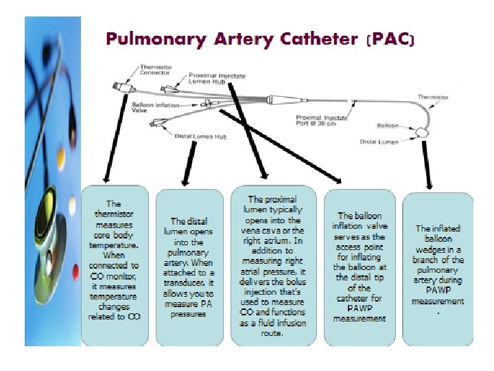
Pulmonary Artery Pressure Monitoring Clinical indications • Measurements obtained – Pulmonary arterial Pressure(PAP) – Pulmonary Capillary Wedge Pressure(PCWP) – Central Venous Pressure(CVP) – Cardiac Output measurement – Mixed Venous Blood gas measurement – Saturation of venous oxygen concentrations(SVO 2)
PA Catheter Waveforms
Determination of Cardiac Output • Factors that determine cardiac output – Heart rate and stroke volume – Alterations are caused by changes in heart rate, preload, afterload, and contractility. • Obtaining cardiac output values – Fick’s method for cardiac output determination – Indicator-dilution methods for cardiac output determination (thermodilution method)
FICK METHOD • 1. MEASURING BLOOD’S OXYGEN BEFORE AND AFTER PASSES THROUGH THE LUNGS. • BLOOD IS REMOVED FROM THE PULMONARY AND BRACHIAL ARTERY AND ANALYZED FOR OXYGEN CONTENT. • SPIROMETER MEASURES OXYGEN CONSMPTION (AMOUNT OF AIR ENERT LUNG EACH MINUTE). • THEN COP WILL BE CALCULATED AS FORMULA
Question • When obtaining a cardiac output, how much time should there be between injections? – – A. 1 minute B. 2 minutes C. 5 minutes D. 10 minutes
Answer • A. 1 minute • Rationale: When injected, the solution passes a temperature probe in the closed system and flows through the right atrium and right ventricle, past thermistor at the tip of the PAC. A curve is produced and used for determining the CO. The average of several CO determinations is required to obtain a final measurement. Serial measurements and averaging are necessary because of the number of physiological variables and the performance of the technical procedure. Waiting approximately 1 minute between injections allows the catheter thermistor to return to baseline.
Procedure for Intermittent Thermodilution Cardiac Output Determination • Ensuring the accurate amount of injectate volume in the syringe • Injecting the volume in a smooth and rapid manner, in less than 4 seconds • Waiting approximately 1 minute between injections to allow the catheter thermistor to return to baseline
• Thermodilution technique is often used-a known amount of solution(saline or d 5 w) of known temperature(room or chilled) is injected rapidly into the right atrial lumen of the PA catheter. A drop in blood temp is detected by a thermister embedded in the catheter tip in the pulmonary artery. • CO is then calculated by a computer from the temperature waveform
Cardiac Index • when CO calculated to reflect body size, it is termed cardiac index. • Normal range 2. 5 -4 L/min/m 2 • Is the preferred value to use clinically because it takes into account body size • CI = CO/Body Surface Area (BSA).
Question • What determines oxygen delivery? – – A. Preload and afterload B. Oxygen demand oxygen delivery C. Oxygen extraction and oxygen deprivation D. Oxygen content and cardiac output
Answer • D. Oxygen content and cardiac output • Rationale: Arterial oxygen delivery (Da. O 2) is the amount of oxygen transported to the tissues. Da. O 2 depends on arterial oxygen content and CO.
Determinants of Oxygen Delivery • Oxygen content – Hemoglobin and oxygen saturation • Cardiac output – Delivers oxygen to the cells – Da. O 2 is CO and arterial oxygen content. – Normal is 1, 000 m. L O 2/minute. – Increase in demand results in compensatory increase in CO.
Determinants of Oxygen Consumption • Oxygen demand – Stress increases demand. – Need adequate delivery of oxygen and cellular extraction of oxygen • Oxygen delivery – Delivery increases > consumption increases > oxygen demand is met. • Oxygen extraction – Amount of oxygen removed from blood for use by cells O 2 debit: inadequate oxygen consumption causes an anaerobic state and cellular hypoxia
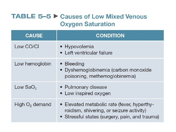
Sv. O 2 • Sv. O 2—mixed venous saturation – Level of oxyhemoglobin in desaturated blood returning to the right ventricle – Can be monitored at the bedside with specialized central venous catheters – Evaluates the balance of oxygen supply, utilization, and demand – Normal ranges from 60% to 80%.
answers CONFIDENTIAL 108