HELICAL GEAR HELICAL GEARS In helical Gear teeths


Gradual engagement of teeth results in smooth and quiet")


- Module in the normal plane is called normal module First Choice")
- is the distance between the corresponding points on the")

- It is the length of the gear tooth")
 : It is the distance")


- The tangential component is a useful")

 The Lewis form factor")

 decides weaker member.")

![Wear Strength of Helical Gear Tooth • K= 0. 16[BHN/100]2 For steel pinion and](https://slidetodoc.com/presentation_image_h2/8d6be6f24ea8f59b975791c2c4b90cf4/image-32.jpg "Wear Strength of Helical Gear Tooth • K= 0. 16[BHN/100]2 For steel pinion and")


 C = 11500 e N/mm for")
 Safety against bending failure. Fb ≥")

- Slides: 37
HELICAL GEAR
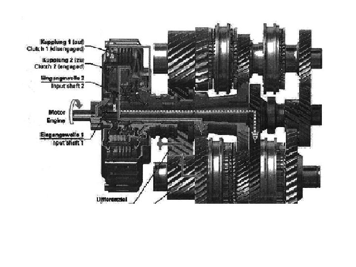
HELICAL GEARS In helical Gear, teeths are cut at an angle, Helix angle, with an axis of the gear. In operation the initial tooth contact of a helical gear is a point which develops into a full line contact as the gear rotates. This is a smoother cycle than a spur which has an initial line contact. Spur gears are generally not run at peripheral speed of more than 10 m/s. Helical gears can be run at speed exceeding 50 m/s when accurately machined and balanced. ----------------------------------Good is not good where better is expected
SPUR GEAR AND HELICAL GEAR
SPUR GEAR AND HELICAL GEAR
HERRINGBONE GEAR
HELIX ANGLE • The helix angle of helical gears ᴪ is an angle made by helix with the axis of rotation. The larger the angle the smoother the motion and the higher speed possible however the thrust loadings on the supporting bearings also increases. For single helical gears, helix angle ranges from 150 to 300. In case of a double or herringbone gear ᴪ values 25, 30, 35, 400 can also be used. These large angles can be used because the side thrusts on the two sets of teeth cancel each other allowing larger angles with no penalty. • -------------------------------- • It’s your attitude, not your aptitude, which determines your altitude
HELICAL GEAR • The gradual engagement makes the gear operation smoother and quieter than with spur gears and results in a lower dynamic factor, Kv. Thus, it can transmit heavy loads at high speeds. Typical usage is automotive transmission for compact and quiet drive. • --------------------------------"The proof of the pudding is in the eating",
ADVANTAGES OF HELICAL GEAR • 1)Gradual engagement of teeth results in smooth and quiet operation. • 2) Dynamic load is low due to gradual engagement. • 3) Contact ratio is high as compared to spur gear. LIMITATIONS 1) creates axial thrust. 2) costlier. • Contact ratio-it can be defined as a measure of the average number of teeth in contact during the period in which a tooth comes and goes out of contact with the mating gear
HELICAL GEAR TERMINOLOGY
HELIX ANGLE • Helix angle is an angle made by helix with the axis of rotation. (ᴪ). • Two meshing parallel helical gears must have same helix angle but the opposite hands. ---------------------------------Proper planning prevents poor performance.
RIGHT HAND HELICAL GEAR When helical gear is placed on the surface with axis vertical, if the teeth are inclined towards right, it is called right hand gear.
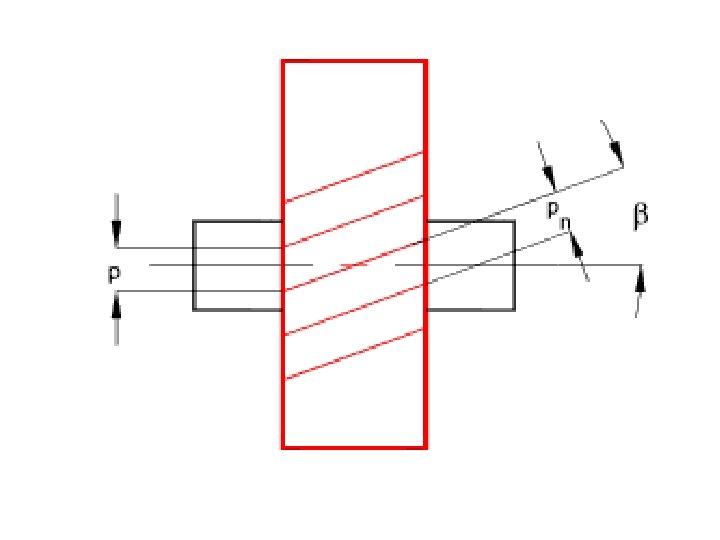
HELICAL GEAR TERMINOLOGY • For helical gears the circular pitch is measured in two ways • The traverse circular pitch (Pt)- Circular pitch measured in the transverse plane(plane of rotation) is called transverse circular pitch. • Transverse module (mt)- Module in transverse plane. Normal Circular Pitch (Pn)- Circular pitch measured in the normal plane to the teeth is called normal circular pitch.
Normal Module (mn)- Module in the normal plane is called normal module First Choice 1. 0, 1. 25, 1. 5, 2, 2. 5, 3, 4, 5, 6, 8, 10, 12, 16, 20, 25, 32, 40, 50. Second Choice 1. 125, 1. 375, 1. 75, 2. 25, 3. 5, 4. 5, 5. 5, 7, 9, 11, 14, 18, 22, 28, 36, 45.
Pitch/module • Axial pitch (Pa)- is the distance between the corresponding points on the adjacent teeth measured on the pitch surface in the axial direction. • Transverse pressure Angle- (Øt) - Pressure angle measured in the transverse plane is called transverse pressure angle. • Normal pressure Angle-(Øn) - Pressure angle measured in the normal plane to the teeth is called normal pressure angle. • Standard normal pressure angle- 14. 50, 200, 22. 50 and 250
GEOMETRICAL PROPORTIONS • ψ =Helix angle • pt = Transverse Circular pitch = Pt = πd / Z • mt = Transverse module = Pt / π = d / Z • p n = Normal circular pitch = Pt. cos ψ • m n =Normal module = mt / cos ψ • p a = Axial pitch = pt / tan ψ • Φt = Transverse pressure angle • ϕ n = Normal pressure angle = tan ϕt = tan ϕ n / cos ψ • d g = Pitch diameter gear = z g. m • d p = Pitch diameter pinion = z p. m
HELICAL GEAR TERMINOLOGY • Face Width(b)- It is the length of the gear tooth measured along a line parallel to the gear axis. • Face Advance(FA)- The distance by which the leading edge of the tooth advances the trailing edge of the same tooth measured along the pitch circle. • Face contact ratio-Mf- The ratio of face advance to the transverse circular pitch is called face contact ratio or axial contact ratio or overlap ratio.
Minimum Face width is given by Centre Distance (a) : It is the distance between the axes of the two mating gears. It is given by Tooth Properties: Addendum (ha) = 1 mn and dedendum (hf) = 1. 25 mn
EQUIVALENT SPUR GEAR AND VIRTUAL NUMBER OF TEETH
EQUIVALENT SPUR GEAR AND VIRTUAL NUMBER OF TEETH • Helical gear is Kinematically equivalent to an imaginary spur gear which is in the normal plane, having the pitch circle radius r’ and the module mn. This imaginary spur gear is called virtual spur gear or formative spur gear. • Pitch Circle diameter of equivalent spur gear-d’d’= 2 r’= d / cos 2 ᴪ • Number of teeth on equivalent spur gear (z’)- •
Minimum No. of Teeth on Helical Pinion • In order to avoid the interference in the Helical gear pair, it must be ensured that the interference does not occur in an equivalent spur gear.
FORCE ANALYSIS OF HELICAL GEAR
FORCE ANALYSIS
FORCES ON SPUR GEAR AND HELICAL GEAR
FORCE ANALYSIS OF HELICAL GEAR Tangential force (Ft)- The tangential component is a useful component for power transmission. It is the tangent to the pitch circle at pitch point. Radial Component (Fr)- Tends to separate the two gears and not useful. Axial force or Thrust force-(Fa)- Acts in axial direction. Resultant force(F)-
BEAM STRENGTH OF HELICAL GEAR TOOTH Helical gear is replaced by virtual spur gear in the plane perpendicular to the tooth and Lewis equation can be used. Fb= σb. b. Mn. Y’ σb= bending endurance strength. Mn= normal module. Y’= Lewis form factor based on virtual number of teeth z’ b = face width of the helical gear, mm.
Lewis Form Factor Based on Virtual Number of Teeth (Y’) The Lewis form factor Y’ is calculated by empirical relations. Y’= 0. 484 - 2. 87/Z’ For 200 full depth involute. Y’= 0. 55 -2. 64/Z’ For 20 stub involute. Y’= 0. 39 - 2. 15/Z’ and composite. For 14. 5 full depth involute Where z’= z/ cos 3 ᴪ
BENDING ENDURANCE STRENGTH • Bending Endurance strength- σb =Sut/3 • Face width- b ≥ 1. 15 π. mn/ sin ᴪ and 9 mn ≤b ≤ 15 mn
WEAKER OF GEAR AND PINION • The product (σb x Y’) decides weaker member. • If (σb x Y’)pinion ≤ (σb x Y’)gear; - pinion is weaker in bending. • If (σb x Y’)pinion≥ (σb x Y’)gear: gear is weaker in bending. • When gear and pinion are made of same material, then pinion is always weaker.
WEAR STRENGTH OF HELICAL GEAR TOOTH • From Buckingham’s equation, Where dp = pitch circle dia. of helical pinion. b = face width of helical gear/pinion. Q = Ratio factor for helical gear. = 2 zg/zg+zp (external gear pair) = 2 zg/zg-zp (for internal gear pair). K= Load stress factor for a helical gear pair.
Wear Strength of Helical Gear Tooth • K= 0. 16[BHN/100]2 For steel pinion and gear • K= 0. 21[BHN/100]2 for C. I. pinion and gear. • K= 0. 18[ BHN/100]2 For steel pinion and C. I. gear. Effective Load on Helical Gear Tooth. It is the total maximum tangential force acting on the helical gear tooth. Theoretical tangential force Maximum tangential force •
In addition to theoretical tangential load, following factors are to be considered to find effective load. Ø Fluctuation of torque due to prime mover and driven machine. It is accounted by application factor , Ka. Ø Non –uniform distribution of load across face width. It is accounted by the load distribution factor , Km.
DYNAMIC LOAD • Preliminary estimation by velocity factor • Feff. = Ka. Km. Ft/Kv. Where Kv is velocity factor. • Precise estimation by Buckingham’s equation • Feff. = Ka. Km. Ft + Fd • Where C= Deformation factor. = K. e. [Ep. Eg/Ep+Eg] • Ep, Eg=Modulii of elasticity of material. • e= Sum of errors on meshing teeth, mm. • K= Factor depending on tooth form.
DYNAMIC LOAD Deformation factor or dynamic factor (c) C = 11500 e N/mm for steel pinion and steel gear. = 8900 e N/mm for C. I. pinion and C. I. gear. = 10000 e N/mm for steel pinion and C. I. gear. Pitch errors on meshing teeth (e)- Sum of pitch errors on two meshing teeth. e= ep+eg ep= pitch error for pinion teeth eg= pitch error for gear teeth Φp = mn + 0. 25√d = Tolerance Factor
SAFETY OF HELICAL GEAR PAIR • • 1) Safety against bending failure. Fb ≥ Feff. Introducing factor of safety, Fb = Feff * F. S. • 2) Safety against wear failure • Fw ≥ Feff. • Introducing factor of safety, • Fw = Feff. * F. S.
Various factors • • Y= Lewis form factor. Q= ratio factor. K= load stress factor. Ka= Application factoror service factor. Km= Load distribution factoror load conc. Factor. Kv= Cv= velocity factor. C= Deformation factor or dynamic factor.