Heat exchanger design Lecture 4 Example and Important


 Jf= 6 x 10 -3 = 0. 199")
- Slides: 19
Heat exchanger design Lecture 4 Example and Important formula’s ©Kalid. H 2019
The general equation for heat transfer across a surface ü hi and ho are tube side and shell side heat transfer Coefficients; calculated by empirical correlations. ü hid and hod are fouling factors for tube side and shell side fluid and can be read from books or handbooks. ü di and do are tube inside and out side diameter. Ft = f (R, S)
Example This example is taken from Coulson and Richardson “Chemical Engineering design” vol 6 chapter 12 example 12. 3 üDesign a shell-and-tube exchanger for the following duty. 20, 000 kg/h of kerosene (42° API) leaves the base of a kerosene side-stripping column at 200°C and is to be cooled to 90°C by exchange with 70, 000 kg/h light crude oil (34° API) coming from storage at 40°C. The kerosene enters the exchanger at a pressure of 5 bar and the crude oil at 6. 5 bar. A pressure drop of 0. 8 bar is permissible on both streams. Allowance should be made for fouling by including a fouling factor of 0. 0003 (W/m 2 °C) -1 on the crude stream and 0. 0002 (W/m 2 °C) -1 on the kerosene stream.
Step 1 : Specification • The specification is given in the problem statement. Mass flow rate of kerosene = 20, 000 kg/h Mass flow rate of crude oil = 70, 000 kg/h Kerosene inlet temperature = 200°C Kerosene out let temperature = 90°C crude oil inlet temperature = 40°C. crude oil outlet temperature = ? (not specified in the problem statement ; need to perform material and energy balance) • The kerosene pressure 5 bar, the crude oil pressure 6. 5 bar. • Permissible pressure drop of 0. 8 bar on both streams. • Fouling factors: crude stream 0. 00035 (W/m 2 °C) -1 , kerosene stream 0. 0002 (W/m 2 °C) -1. • • • The specification is not complete without calculating the out side temperature of crude oil and Q
• Q = ḿCΔT As a first trial take the mean temperature of the crude oil as equal to the inlet temperature, 40°C; specific heat capacity at this temperature = 2. 01 k. J/kg°C. The specific heat at this temperature is 2. 05 k. J/kg°C. A second trial calculation using this value gives t 2 = 77. 9°C and a new mean temperature of 58. 9°C. There is no significant change in the specific heat at this mean temperature from the value used, so take the crude stream outlet temperature to be 77. 9°C, say 78°C.
Step 2: Physical Properties Kerosene temperature specific heat thermal conductivity density viscosity Crude oil temperature specific heat thermal conductivity density viscosity temperature specific heat inlet 200 2. 72 0. 130 690 0. 22 inlet 78 2. 09 0. 133 800 2. 4 78 2. 09 mean 145 2. 47 0. 132 730 0. 43 mean 59 2. 05 0. 134 820 3. 2 59 2. 05 outlet 90 °C 2. 26 k. J/kg°C 0. 135 W/m°C 770 kg/m 3 0. 80 m. N sm-2 outlet 40 °C 2. 01 k. J/kg°C 0. 135 W/m°C 840 kg/m 3 4. 3 m. N sm-2 40 °C 2. 01 k. J/kg°C
Step 3: Guess overall coefficient • Use figure 12. 1 and Table 12. 1(Coulson vol. 6, chapter 12) or other heat exchanger design books to locate U 0 Start with initial guess of Uo = 300
Step 4: Exchanger type and dimensions • An even number of tube passes is usually the preferred arrangement • Start with one shell pass and 2 tube passes read value of Ft from Figure 12. 19 Calculate
Ft = 0. 88 Step 5: Heat transfer area
Step 6: Layout and tube size • Exchanger type • Using a split-ring floating head exchanger for efficiency and ease of cleaning. • Construction material • Neither fluid is corrosive, and the operating pressure is not high, so a plain carbon steel can be used for the shell and tubes. • Fluid allocation • The crude is dirtier than the kerosene, so put the crude through the tubes and the kerosene in the shell. • Tube dimension • Use 19. 05 mm (3/4 inch) outside diameter, 14. 83 mm inside diameter, 5 m Long tubes (a popular size) on a triangular 23. 81 mm pitch (pitch/dia. = 1. 25).
Step 7: Number of tubes • So, for 2 passes, number of tubes per pass = 120 Check the tube-side velocity at this stage to see if it looks reasonable
Step 8: Bundle and shell diameter From Table 12. 4, for 2 tube passes, Kl = 0. 249, n, = 2. 207, Shell clearance can be read from Figure 12. 10, so for a split-ring floating head exchanger the shell clearance is 56 mm
Step 9: Tube-side heat transfer coefficient For turbulent flow • For laminar flow •
Heat transfer correction factor which is similar to the friction factor used for pressure drop Read jh factor from figure 12. 23
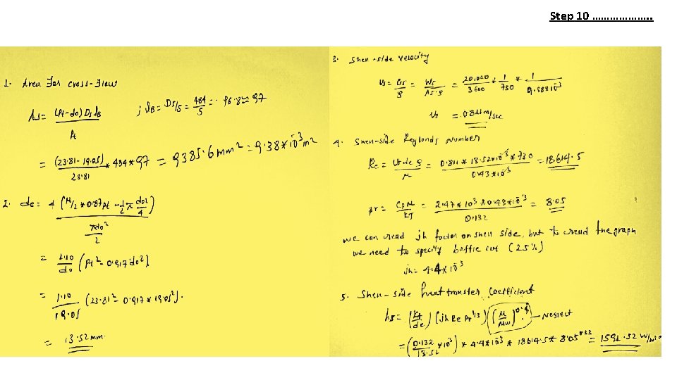
Step 10: Shell-side heat transfer coefficient
Wetted perimeter = the part of pipe in contact with the fluid Free Flow Area for Triangular Layout: Wetted Perimeter for triangular layout
Step 11: Overall coefficient This is below the initial estimate of 300 W/m 2°C.
Step 12: Pressure drop (tube side) Jf= 6 x 10 -3 = 0. 199 bar The pressure drop is within acceptable range N. B the example in the book follows correcting the pressure drop since it exceeds the limit, so you have to refer the Text for possible procedure in adjusting the pressure drop.