
Health Safety Laboratory Health Safety Executive Buxton Derbyshire
Health & Safety Laboratory Health & Safety Executive Buxton, Derbyshire United Kingdom Health & Safety Laboratory
FIRE TESTING OF ENGINE FLAME BREAKOUT SHIELD MATERIALS S F Jagger, K Moodie, R J Bettis Health & Safety Laboratory, Buxton, UK B C R Ewan University of Sheffield
Objectives • Traditionally flame breakout shields have bee fabricated from germanium rich materials. • As germanium becomes increasingly scarce the use of shields made from other alloys is being explored. • Develop a realistic small scale test for assessing performance of new materials alongside traditional methods.
Steps in this process • Define the design fire The event against which the shield must provide protection • Design test rig to model these conditions Must be repeatable, controllable & realistic • Measure test piece exposure conditions Correspondence with design fire conditions Establish pass/fail criteria • Test according to protocol developed

Design fire conditions Regulatory background FAA – AC 20 -135 powerplant installations Special fireproof requirements for engine case burnthrough Location of protection same as in real installation Minimum flame temperature 1920 K Flame emerging through 1’’ orifice Source conditions same as real combustor chamber Test duration – 3 minutes

Barrel shock/mach disc conditions Po - reservoir pressure Pb - back pressure
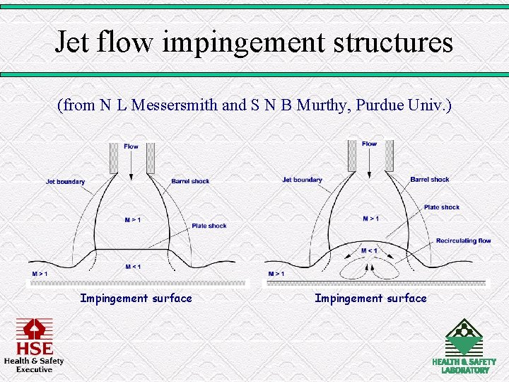
Jet flow impingement structures (from N L Messersmith and S N B Murthy, Purdue Univ. ) Impingement surface
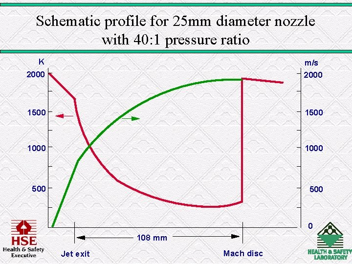
Schematic profile for 25 mm diameter nozzle with 40: 1 pressure ratio K 2000 m/s 2000 1500 1000 500 0 108 mm Jet exit Mach disc
Development needs • Low cost, low weight shield materials and strategies
Measurement needs • Heat transfer rates to impingement surfaces • Profiles of velocity, density & temperature
Measurement difficulties • Intrusive devices shock structures unrepresentative conditions • • Radiation losses Protection of probes Introduction of seeding Wide range of temperature, velocity, density
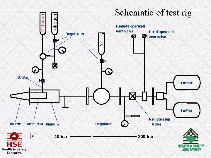
Nitrogen Remote operated vent valve Regulators Hand operated vent valve Air Methane Schematic of test rig 60 Bar 1 m 3 air Nozzle Combustor Plenum 40 bar Regulator Remote stop Valve 200 bar
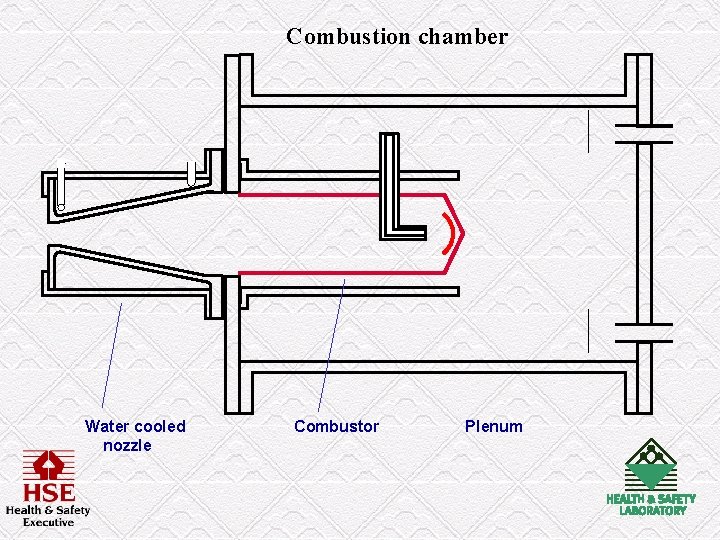
Combustion chamber Water cooled nozzle Combustor Plenum
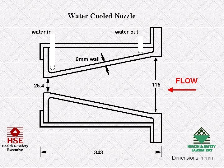
Water Cooled Nozzle water in water out 8 mm wall 115 25. 4 343 FLOW Dimensions in mm
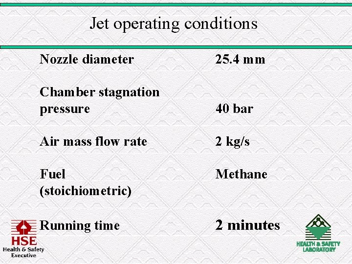
Jet operating conditions Nozzle diameter 25. 4 mm Chamber stagnation pressure 40 bar Air mass flow rate 2 kg/s Fuel (stoichiometric) Methane Running time 2 minutes
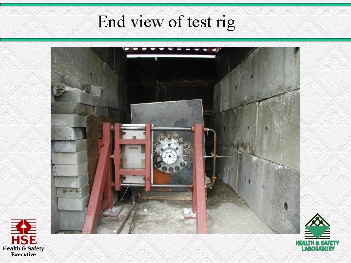
End view of test rig
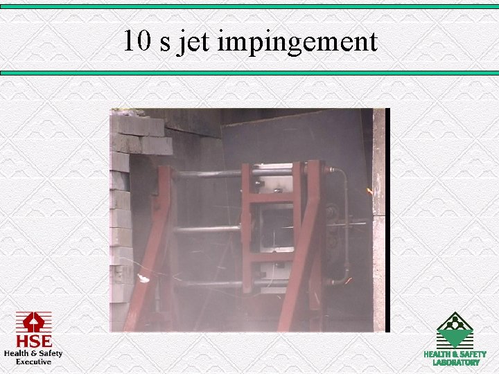
10 s jet impingement
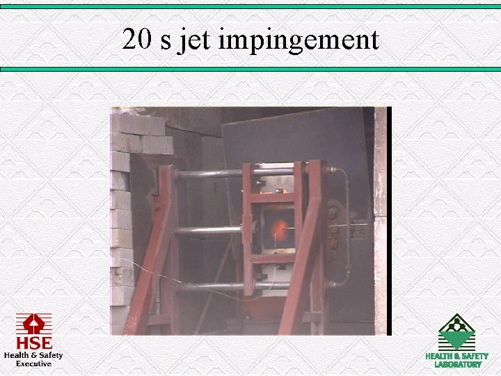
20 s jet impingement
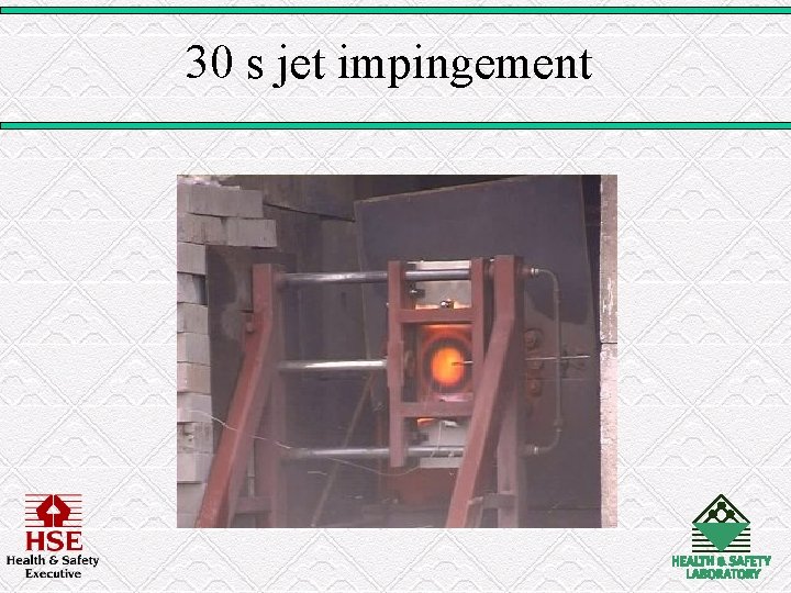
30 s jet impingement
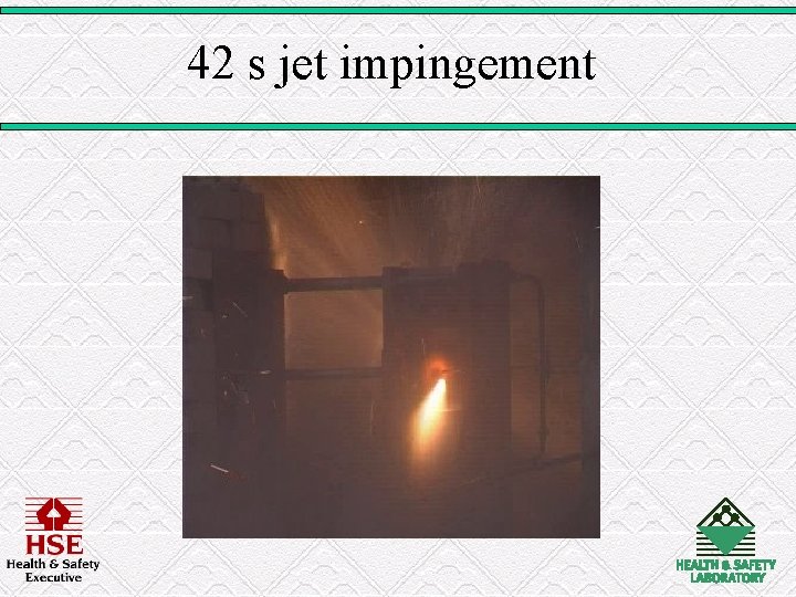
42 s jet impingement
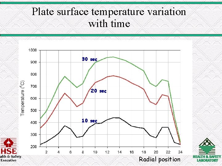
Plate surface temperature variation with time 30 sec 20 sec 10 sec Radial position
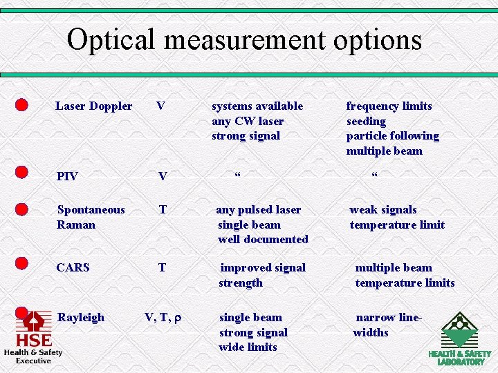
Optical measurement options Laser Doppler V PIV V Spontaneous Raman T any pulsed laser single beam well documented CARS T improved signal strength multiple beam temperature limits single beam strong signal wide limits narrow linewidths Rayleigh V, T, systems available any CW laser strong signal “ frequency limits seeding particle following multiple beam “ weak signals temperature limit
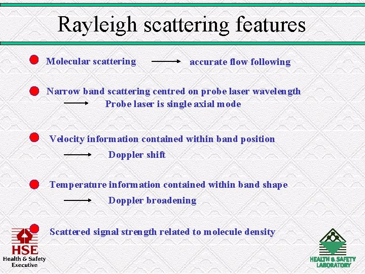
Rayleigh scattering features Molecular scattering accurate flow following Narrow band scattering centred on probe laser wavelength Probe laser is single axial mode Velocity information contained within band position Doppler shift Temperature information contained within band shape Doppler broadening Scattered signal strength related to molecule density
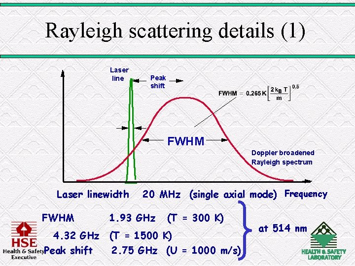
Rayleigh scattering details (1) Laser line Peak shift FWHM Doppler broadened Rayleigh spectrum Laser linewidth FWHM 20 MHz (single axial mode) Frequency 1. 93 GHz (T = 300 K) 4. 32 GHz (T = 1500 K) Peak shift 2. 75 GHz (U = 1000 m/s) at 514 nm
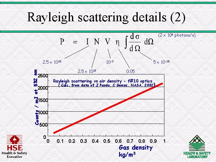
Rayleigh scattering details (2) (2 x 10⁶ photons/s) Counts / m. J at 532 nm 2. 5 x 10²⁰ 2500 2000 10 -3 5 x 10 -28 2. 5 x 10¹⁹ 0. 05 Rayleigh scattering vs air density - f#10 optics ( Calc. from data of J Panda, C Gomez, NASA, 2002 ) 1500 1000 500 0 0 0. 1 0. 2 0. 3 0. 4 0. 5 0. 6 0. 7 0. 8 0. 9 Gas density kg/m 3 1
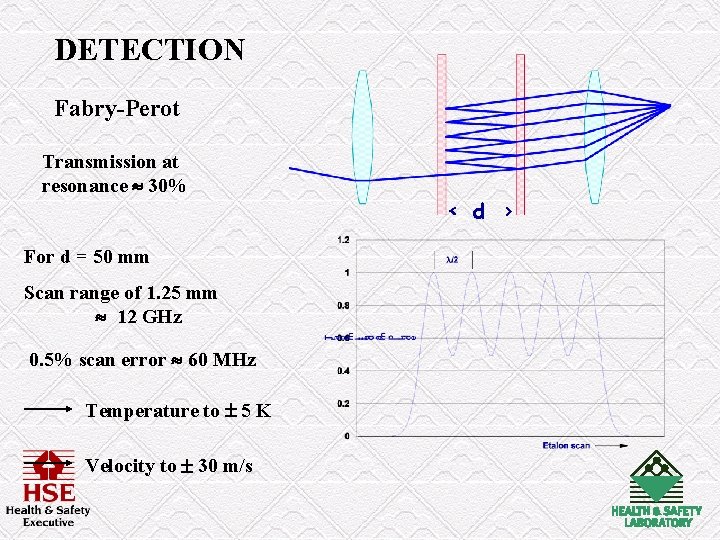
DETECTION Fabry-Perot Transmission at resonance 30% For d = 50 mm Scan range of 1. 25 mm 12 GHz 0. 5% scan error 60 MHz Temperature to 5 K Velocity to 30 m/s < d >
CONCLUSIONS(1) • High enthalpy impinging jet problem remains area for investigation - new shield materials key objective • Workable test rig developed well representative of design fire conditions • Test conditions are repeatable and variable • Main problem is measurement and validation of test conditions • Non-intrusive laser-based measurements present the best way forward
CONCLUSIONS(2) • Rayleigh scattering offers possibility of good signal levels in hostile jet environment • Temperature, velocity and density available from single measurement • Regulation test times may allow jet traversing or laser sheet probe to explore heat transfer behaviour
- Slides: 28