Hardware description languages introduction intellectual property IP introduction
 • introduction to VHDL and Verilog")
: HDL is a language to describe hardware, just like it")

: HDL's are an effective way to describe components in which the")
 Hardware Description")

: simulators are examples of")


 module NAND(in 1,")
: 30 fig_A 1_02")
![Verilog computation and initialization examples: (my. Wires[2] is output, and gate is named a](https://slidetodoc.com/presentation_image_h/2d842a081ad4763045b756c9d0ce74df/image-31.jpg "Verilog computation and initialization examples: (my. Wires[2] is output, and gate is named a")


 Inputs / outputs: 42 fig_A 1_16")


- Slides: 52
Hardware description languages: introduction • intellectual property (IP) • introduction to VHDL and Verilog • entities and architectural bodies • behavioral, structural, and dataflow views • examples 1
hardware description languages (HDL's): HDL is a language to describe hardware, just like it says; typically a HDL tries to use programming-language-type syntax and constructs to describe hardware, allowing the user to avoid the use of schematics 2
Some things HDL's must deal with: parallel activity (e. g. , in a half adder, both the XOR and AND gates receive inputs simultaneously) vector inputs (e. g. , in an 8 -bit adder, the inputs are each 8 bits and the output is 9 bits) timing--both sequential and combinational logic (e. g. , in a register the interaction between the clock input and the state changes must be described) levels of abstraction ideally will support both analysis and synthesis for hardware components/systems 3
intellectual property (IP): HDL's are an effective way to describe components in which the internal workings ("intellectual property") are proprietary but the interface to other components must be public "popular" HDL's: VHDL, Verilog Both have “AMS” (Analog and Mixed Signal) extensions 4
Two main HDLs: VHDL / Verilog VHDL--Very High Speed Integrated Circuit (VHSIC) Hardware Description Language Standards--IEEE 1076 -1987; 1076 -1993; Ada-like language Additions--VHDL-AMS--Analog & Mixed Signal Verilog— 1985; proprietary to Cadence until 1990 (“open Verilog”) C-like language Additions—Verilog-AMS—Analog & Mixed Signal NOTE: this course is NOT designed to make you a VHDL or Verilog expert! The Altera tools (as well as other synthesis tools) work best with simpler HDL constructs (e. g. , structural representations, modest levels of 5 nesting)
VHDL and Verilog: Behavioral, Structural, and “Dataflow" views supported Physical views generally not supported --descriptions do not encompass the low-level physical details of a design --in particular descriptions can be "technology independent"; this supports REUSABILITY --for simulation, may add details of a particular technology [this quarter—HDL designs are tied to the specific technology of the chosen Altera device] Both languages allow for “testbenches” to aid simulaton (altera does not support the testbench concept; bestsupported simulation is through graphical waveforms) 6
what can HDLs be used for? design entry simulation ("analysis"): simulators are examples of "discrete event simulators" E 11 E 2 E 12 E 22 E 3 E 4 E 111 E 41 time synthesis: HDL description can be turned into a circuit layout by powerful "silicon compilers" 7
8
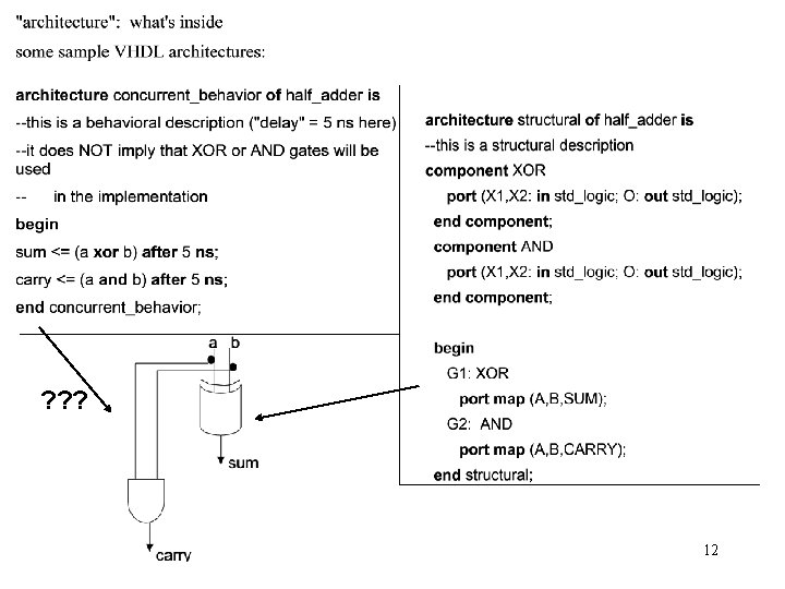
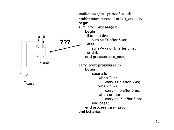
VHDL *entity—interface to the outside world *architectural body—functionality *one entity can be paired with several architectural bodies, for example a structural body and a behavioral body 9
Note: keywords, comment, “entity” syntax 10
11
Full adder example: 14
15
16
17
18
19
20
21
22
23
24
Verilog: Much of the following is taken from the introduction by Dan Hyde at: http: //www. eg. bucknell. edu/~cs 320/1995 -fall/verilog-manual. html Other references can be found at: http: //www. verilog. net/docs. html Architectural, behavioral, gate, and switch levels supported Gate level: logic elements (structural) Switch level: transistor level Verilog program can be used for design, simulation, synthesis Basic construct: module Verilog program consists of interconnected modules Usually a “top” module encapsulates all the others NOTE: Altera does not allow simulation statements 25
Verilog: a C-like language Basic parts of a Verilog module: 26 fig_A 1_01
Example: a simple structural module in Verilog 27
Another example of a structural module in Verilog: 28 fig_A 1_09
Some simple examples of combinational logic: // NAND gate (behavioral model) module NAND(in 1, in 2, out); input in 1, in 2; output out; assign out = ~(in 1 & in 2); endmodule //AND gate (structural module) module AND(in 1, in 2, out); input in 1, in 2; output out; wire w 1; NAND 1(in 1, in 2, w 1); NAND 2(w 1, out); endmodule 29
Typical declarations (“vectors”): 30 fig_A 1_02
Verilog computation and initialization examples: (my. Wires[2] is output, and gate is named a 1) 31 fig_A 1_03
Verilog combinational functions-structural primitives: 32 fig_A 1_07
33 table_A 1_00
34 table_A 1_01
Modeling delays: 35 fig_A 1_10
36 fig_A 1_11
37 fig_A 1_12
38 fig_A 1_13
39 fig_A 1_14
40 fig_A 1_15
Dataflow: continuous assignment Syntax: Assign destination = source *Destination cannot be a register or a function *any change in rhs forces a change in lhs—assignment is “always active” Examples: 41
(delays added) Inputs / outputs: 42 fig_A 1_16
Rise and fall times can also be added 43 fig_A 1_19
Dataflow models of sequential logic can be constructed: fig_A 1_21 44
Behavioral level: In C or C++, execution is sequential In Verilog execution is concurrent *Program is a collection of initial or always blocks; *Each block is a separate flow of control, independent of the others *Each block is defined by begin and end statements *Blocks cannot be nested Two types of procedural assignment: Blocking: sequential: A = B; Nonblocking: parallel: A <= B; Both can have delays added Example: 45
46
Additional examples from text: fig_A 1_24 47
48 fig_A 1_25
fig_A 1_26 49
50 fig_A 1_27
51 fig_A 1_28
fig_A 1_29 52