H Stripping D Raparia Brookhaven National Laboratory Upton

H- Stripping. D. Raparia Brookhaven National Laboratory Upton, NY, USA Upgrading Existing High Power Proton Linac ESS, Lund, Sweden November 8 -9, 21016

Outlines § Introduction § Physical Processes - Striping by Residual gas - Stripping by Foil § Field Stripping - Stripping by Magnetic/Electrical fields - Intra Beam Stripping - Stripping by Back Body Radiation § Use of Stripped Electrons § Conclusions

H- Ion e P e § Hydrogen atom with an extra electron § H- , first electron binding energy 13. 6 e. V, second loosely bound 0. 75 e. V § H- generated with ion source generally with help of Cs

Why H- ? Circulating H+ Stripping foil Injected H- In 1966 Budker proposed to increase Intensity in the circular accelerators by charge exchange by stacking multiple turns of ions into the same physical space -G. I. Budker, et al, `` Experimental study of Charge Exchange injection” 1966 -D. Raparia, et al, `` Efficient Capture of 20, 000 Turn from TRIUMF”, IEEE Tran. Nucl. Sci. NS -32, 2456, 1985 -D. Raparia, `` Estimate of the Number of Foil Hit for Charge Exchange Injection”, PAC 2011 Megnetron Ion Source, 100 m. A @ 35 ke. V
 § To beat the Liouville theorem while injection to a")
Why H- ? (Physicist) § To beat the Liouville theorem while injection to a ring which state: “The particle density in the phase space is constant in conservative forces “ § Liouville’s can be circumvented by use of dissipative forces e. g. to strip an H- beam with a foil and merge it with a proton beam. The interaction with foil is the dissipative force.
 P circulating and P injection Either come out with the")
Why H- ? (Engineer) P circulating and P injection Either come out with the same Angle at different positions, or At the same position with different angle=> emittance growth Magnet r’ r’ r r
 P circulating , H- injection p H- Foil r’ r Both")
Why H- (Engineer) P circulating , H- injection p H- Foil r’ r Both beam at the same position and angle, No emittance growth
")
Residual Gas Stripping • Total electron cross section , single (H- to H 0) and double (H- to H+) stripping ( ~1/β 2) Up tp 10 Me. V G. H. Gillespie Phy. Rev. A 15 563 (1977) G. H. . Gillespie Phy. Rev. A 16 943 (1977)
 Y scale: Arb. unit P: 10 -8 Torr(H")
Residual gas stripping (cont. . ) Y scale: Arb. unit P: 10 -8 Torr(H 2) § Life time of Hni(cm 3)=3. 3. 1016. P(torr) § Frac_loss/m Total measured electron loss cross section for H (unit 10 18 cm 2) E (Me. V) H N 0. 035 773 1490 10 2. 1 30. 7 400 0. 2 800 1 O 32 AR Xe 1760 4180 83 500 3
 § Double stripping has highest probability at low")
Residual gas stripping (cont. . ) § Double stripping has highest probability at low energies and capture into RF bucket and transported to higher energies specially in magnetic LEBT. § Seen at BNL, LANL, J-PARC § Can be avoided to accelerate to higher energies by dipole ( LEBT, BNL), chicane (MEBT, J-PARC), Frequency Jump (SNS) ….

H- Space Charge Neutralization and Stripping in magnetic LEBT § To overcome the space charge forces, magnetic LEBT utilized space charge neutralization be residual gas ions. § During the charge neutralization of the beam, space charge forces changes, resulting change in beam size, matching condition at the following section of accelerator and transmission through the accelerator are continuously changes until beam reached an equilibrium state. § Neutralization time is inversely proportional to residual gas pressure and stripping losses are directly proportional. These are competitive processes, has to be optimized case by case bases.
 Left Triangular are represents Losses due to")
H- Stripping and Neutralization (cont. . ) Left Triangular are represents Losses due to Neutralization. Top rectangular are represent Losses due to the stripping 0. 40 Total Losses Total losses due to stripping And neutralization as function Of residual gas pressure for 200 cm long LEBT and 500 us long beam pulse length. 0. 50 0. 30 0. 20 0. 10 0. 00 2. 00 E-06 2. 00 E-05 Pressure in the LEBT (Torr) 2. 00 E-07 H N Ar Kr Xe
 1 5 Energy (Ge. V) 1")
SNS and ESS Parameter SNS ESS Power (MW) 1 5 Energy (Ge. V) 1 2 Ave. Cur (m. A) 1 2. 5 Peak Cur (m. A) 33 62. 5 Freq. (MHz) 402. 5 352. 2 N (micro Bunch) 3. 05 e 8 7. 19 e 8 β 0. 87 0. 95 γ 2. 06 3. 13 βγ 1. 79 2. 97 β 4 γ 2 2. 43 7. 98 Dose rate (mrem/h) ~ 0. 33*(E(Me. V)-9)1. 8 /E ratio 5 2 2. 5 1. 89 1. 14 2. 36 1. 09 1. 52 1. 65 3. 28 (for Cu)

Gas stripping 0 -90 Me. V 90 -186 Me. V 186 -1000 Me. V 1000 -2000 Me. V HEBT SNS mrem/h (x 1 E-2) ESS mrem/h (x 1 E-2) 0 -10 10 -20 0. 02 -0. 81 81. 0 0 -25 0. 25 -0. 5 0. 05 -2. 025 -3. 58 358. 00

Foil stripping, Carbon foil efficiencies Webber & Hojvat, 1979 Gulley et al. , 1996 200 Me. V 800 Me. V H+ H+ HH- H 0
 2000")
Stripping Cross Section 800 Me. V 200 Me. V (10 -18 cm 2) 2000 Me. V ( , 0) 0. 676± 0. 009 1. 56± 0. 14 0. 529 (0, +) 0. 264± 0. 005 0. 60± 0. 10 0. 500 ( , +) 0. 012± 0. 00 0. 08 ± 0. 13 0. 009 (scale)
 –")
Foil Issues Foil issues: Assuming Carbon Foil – Stripping efficiencies : (~1/β 2) – Multiple Coulomb scattering (~1/γ 2β 4) – Large angle and Nuclear scattering(β 2) – Energy straggling (~1/β 2) – NT – Acceptance – Emittance(N, RMS) – Ave. Number foil hit – Heating – Stress and buckling – Lifetime – Radiation – Stripped Electron – Emittance Growth SNS 300 μg/cm 2 15 e-6 Rad 4. 25 E-6 Rad 840 e. V 1060 160 0. 25 7 1100 ESS 345 μg/cm 2 4. 57 E-6 Rad 5. 0 E-6 Rad 705 E-6 e. V 550 300 0. 25 2 <800 1000 mrem/h more SNS 1380 mrem/h

Magnetic Field Stripping § When H- move in the transverse magnetic filed B it experiences a Lorentz force that band the trajectory and also tends to break it up since protons an electron are bent in the opposite direction and the binding energy of second electron only 0. 755 e. V. § Due to quantum mechanical nature , the breakup is a probabilistic process. In the ion rest frame, stripping force is electric field E that is the Lorentz-transform of the transverse magnetic field B in the lab frame E [MV/m]=319. 7 p(Ge. V/c]B[T] =542 MV/m for T=1 Ge. V H-, B=1 T
 Life time ( Scherk’s formula Can J. Phys. v. 57,")
Field Stripping (cont. ) Life time ( Scherk’s formula Can J. Phys. v. 57, p. 558 (1979): § Frac. Loss Plot from M. Plum

Life time of Stark States § the H 0 from stripper foil will in different energy level. In the electric filed (Lorentz transform magnetic field), each energy level n of H 0 split into n(n+1)/2 Stark State § Life time of these state can be calculated, and is dependent of particle energy and magnetic field. Generally >5 state will strip near foil, <2 state won’t stripped. H 0* stripping at 1. 0 Ge. V Plot from T. Gorlov Peak field in chicane #3 = 0. 14 T Field at foil = 0. 175 T

Blackbody Radiation Striping § During Project X design, it was discover at very high energy (> 4 Ge. V) Doppler shifted black body radiation will cause H- stripping. photon distribution cross section Plot from W. Chou 0. 75 e. V
 Energy Dependence Temperature Dependence At 305 K (90 F) and")
Blackbody Radiation Stripping (cont…) Energy Dependence Temperature Dependence At 305 K (90 F) and 8 Ge. V, H loss rate = 0. 8 10 6 m 1 • Below 4 Ge. V H- stripping losses are negligible. • Cooling of the beam pipe can reduce losses order of magnitude. Courtesy of W. Chou March 15 -17, 2005 22

Intra Beam stripping § First observed in LEAR (Chanel, 1987 σ=3. 6 ± 1 x 10 -15 cm 2). § Unexpected loss and activation were discover during SNS power ramp up. V. Lebedev explained, the losses is due to intra beam stripping. § Binary collision inside an H- micro-bunch result in stripping one of their electron and subsequent particle loss. Particle loss rate is proportional to intra beam stripping cross section and square of number of particle in the micro bunch.

SNS SCL losses vs. Peak Current H-, strong focusing optics H-, week focusing optics Proton, strong & week focusing optics H- beam was stripped by foil after RFQ and match to linac by quads in MEBT for proton run for this comparison. First Observation of Intrabeam Stripping of Negative Hydrogen in a Superconducting Linear Accelerator, ” A. Shishlo, J. Galambos, A. Aleksandrov, V. Lebedev, and M. Plum, Phys Rev Letters 108, 114801 (2012).

Intra Beam Stripping Mitigations V. Lebedev et al. § Decreasing the particle density in the phase space - reducing the frequency (almost linear effect) - reducing the transverse phase advance per meter to a limit (to compensate RF and space charge defocusing)
 VESS/VSNS= 1. 49 (assuming")
Example ESS § § § NESS/NSNS= 2. 36 (micro bunch) VESS/VSNS= 1. 49 (assuming same emittance) θx, y, z(ESS)/θx, y, z(SNS)= 0. 84 (assuming same emittance) Loss Factor ~ 3. 5 SNS losses 0. 05 -0. 17 n. A => 1 – 13 mrem/h =>ESS Losses =0. 18 -0. 6 n. A =>3. 8 - 85. 9 mrem/h

SNS Activation SNS to ESS Intensity Factor Energy Factor IBS Factor 2. 5 1. 4 3. 5

Uses of stripped electron and H 0 § § § Profile measurement in three dimension Emittance measurement in all three dimension Energy measurement Energy spread measurement Space charge potential ( current density) measurement § H- current measurement

Conclusions § H- injection into the ring outweighs all the stripping issues in the linac and transport line. § During last decade Intra beam stripping and black body radiation stripped were identify as topics should be consider during design. § H- stripping has not limited the performance of linac yet. § Use of stripped electron can be explore more.

Backup slides

2010: Profile measurement By LPM at HEBT Horizontal 31 Vertical

Energy Scan Measured electron energy verse time in the pulse 0. 6% drop in the energy during 0. 5 ms beam pulse A Gaussian is fitted to the derivative of the signal vs. grid voltage data. The center (64. 2 k. V) is the average electron energy from the beam motion and the width (σ=0. 87 k. V) is from beam-energy spread and from the space-charge potential spread. The proton energy is mp/me=1836 times the measured electron energy: Ep = 118 Me. V σp = 1. 6 Me. V
 Transverse Optical System Labview H- Beam profile")
Profile Measurement Nd: YAG ( =1064 nm) Transverse Optical System Labview H- Beam profile e from H- are guided by magnetic field Solenoid Magnetic Field

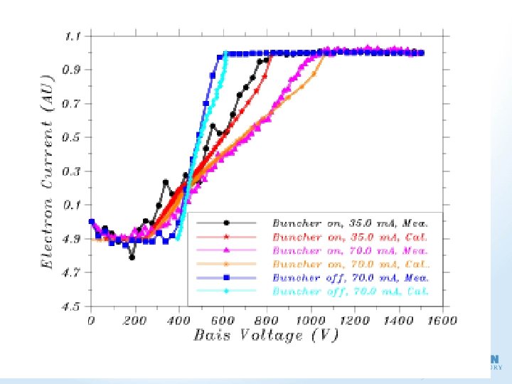
Space Charge Potential DC Beam Te =Te 0+ r Ee 0=7. 5. 105/1838 =408 V ax=13. 5, ay=7. 0 mm, bx=by= 38 mm R=(x+y)/2=10. 25 mm V 0(70 m. A) ~ 200 V Te=408+200 =~600 V

KOBRA Simulations X-Z Plane Axial Mag. Field =0 X-Y Plane; Axial Mag. Field =100 G X-Z Plane Axial Mag. Field =100 G

SCP Bunched Beam Electric Field due to uniform ellipsoid EH- = 750, 000 e. V EH-= 20, 000 e. V Ee = 408 e. V Ee = 10. 9 e. V X-Z Plan SCP Potential in X-Z Plane. LASER

Buncher ON, Full Current

Stripped Electrons in H- Bunch
 << SCP) - Space Charge Potential")
Energy Measurement § At low energies ( E(me/mp) << SCP) - Space Charge Potential (SCP) - Bunch Length and Bunching Factor § At high ( E(me/mp) >> SCP) - Energy Spread ( E)
- Slides: 40